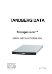
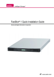
1
StorageWorks by Compaq
1
2
NAS B3000
Rack Installation Instructions
6
4
3
5
7
8
9
Open Card Completely Before
Beginning Installation Procedures
Identify the device and storage enclosure components.
Item
NOTICE
© 2002 Compaq Information Technologies Group, L.P.
Compaq, the Compaq logo, and StorageWorks are trademarks of
Compaq Information Technologies Group, L.P.
All other product names mentioned herein may be trademarks of their
respective companies.
Compaq shall not be liable for technical or editorial errors or omissions
contained herein. The information is provided “as is” without warranty
of any kind and is subject to change without notice. The warranties for
Compaq products are set forth in the express limited warranty statements
accompanying such products. Nothing herein should be construed as
constituting an additional warranty.
Printed in the U.S.A.
Important Safety Information
Before installing this product, read the Important Safety
Information document provided.
StorageWorks NAS B3000 by Compaq
Rack Installation Instructions
First Edition (February 2002)
Part Number: 259123-001
Compaq Computer Corporation
259123- 001
1
2
3
4
5
6
7
8
9
Description
Device
Power cords for device power supplies
Remote Insight Lights-Out Edition board power cable and adapter
"Y" cable for Remote Insight Lights-Out Edition board
Fiber cables
Rack-mounting hardware for the device
Storage enclosure
Power cords for storage enclosure power supplies
Rack-mounting hardware for the storage enclosure
WARNING: To reduce the risk of personal injury or damage to the
equipment, at least two people are needed to safely remove each
component from the shipping carton.
Installation Tips
Begin installing rack components at the bottom of the rack or
immediately above a previously installed component, and then
work toward the top of the rack.
Have a Phillips screwdriver and a pencil available before
beginning the procedure.
Do not tighten the rack-mounting rail screws completely until
after the component is inserted into the rack. The small amount
of play helps position the rails to the exact width of the
component being installed.
Always make sure that the rack-mounting rails are completely level.
Observe local occupational health and safety requirements and
guidelines for manual material handling.
Because higher ground-leakage currents are associated with
connecting several pieces of equipment to the same power
source, Compaq recommends using a power distribution unit
(PDU) that provides a supplementary ground conductor.
Connect this supplementary ground conductor permanently to a
suitable building ground terminal. Do not use common power
outlet strips for this equipment.
Get help to lift and stabilize the product during installation or
removal, especially when the product is not fastened to the rails.
Temperature Requirements
WARNING: This product is very heavy. To reduce the risk of personal
injury or damage to the equipment:
·
·
WARNING: When the product is installed into or removed from the
rack, the product is unstable when not fastened to the rails.
Space Requirements
Front clearance. Leave at least 64 cm (25 in) in front of the rack
to allow the door to open all the way and to provide
adequate airflow.
Back clearance. Leave at least 77 cm (30 in) behind the rack to
allow easy servicing and to provide adequate airflow.
Power Requirements
WARNING: To reduce the risk of personal injury, fire, or damage to the
equipment, do not overload the AC supply branch circuit that provides
power to the rack. Consult the appropriate electrical authority for the
wiring and installation requirements of your facility.
Balance circuit power load. The circuit power load must be
balanced between available AC supply branch circuits.
Limit circuit current load. The overall system AC current load must
not exceed 80 percent of the branch circuit AC current rating.
Limit power strip load. If power strips are used, the load should
not exceed 80 percent of the marked electrical current rating.
Installation of this equipment shall be in accordance with local/
regional electrical regulations governing the installation of
information technology equipment by licensed electricians. This
equipment is designed to operate in installations covered by the
National Electric Code (ANSI/NFPA 70, 1993) and the code for
Protection of Electronic Computer/Data Processing Equipment
(NFPA-75, 1992).
To ensure continued safe and reliable operation of the
equipment, locate the system in a well-ventilated, climatecontrolled environment.
The Compaq Maximum Recommended Ambient Operating
Temperature (TMRA) for most device products is 35°C (95°F).
Therefore, the temperature in the room where the rack is located
should not exceed 35°C (95°F).
The operating temperature inside the rack is always higher than
the room temperature and is dependent on the configuration of
equipment in the rack. The maximum internal rack temperature
for your configuration should not exceed the values in the Rack
Internal Temperature Maximums table (below).
Rack Internal Temperature Maximums
Equipment Included
Compaq StorageWorks TM
NAS B3000 Device
Compaq rack-mountable
options
Other manufacturers’
options
Maximum Internal Rack Temperature
50°C/122°F
40°C/104°F
See manufacturing specifications
CAUTION: To reduce the risk of damage to the equipment when
installing third-party options:
·
·
For electrical power ratings on options, refer to the rating label on
the product or to the user documentation supplied with that
option.
Make sure that the option equipment does not impede airflow
to a rack-mountable StorageWorks NAS B3000 device or
increase the internal rack temperature beyond the maximum
rating specified by Compaq.
Make sure that the manufacturer's maximum recommended
ambient operating temperature of the option equipment is not
exceeded after the equipment is installed into the rack.
Airflow Requirements
Grounding Requirements
For proper operation and safety, this equipment must be properly
grounded (earthed). In the United States, install the equipment in
accordance with NFPA 70-1993 (National Electric Code) Article
250, as well as any local and regional building codes. In Canada,
the equipment should be installed in accordance with Canadian
Standards Association, CSA C22.1, Canadian Electrical Code. In
all other countries, the installation should follow any regional or
national electrical wiring codes, such as the International
Electrotechnical Commission (IEC) 364, parts 1 through 7. All
power distribution devices used in the installation, including
branch wiring, receptacles, and so forth, should be listed or
certified ground-type devices.
WARNING: To reduce the risk of personal injury, fire, or damage to
the equipment, do not overload the AC supply branch circuit that
provides power to the rack. Consult the electrical authority for the
wiring and installation requirements of your facility.
The device draws cool air in through the front door and exhausts
warm air out the rear door. Do not block ventilation apertures.
CAUTION: If a third-party rack is used, the following minimum
requirements must be observed to ensure adequate airflow and to
prevent damage to the equipment:
·
·
·
Front: The front must have a minimum of 63.5 cm (25 in) of
unrestricted ventilation.
Side: The clearance between the installed module and the side
panels of the rack must be a minimum of 6.9 cm (2.75 in).
Rear: The clearance between the back of the rack and the wall
must be a minimum of 76.2 cm (30 in), and the equipment
must be operated without a rear door.
Installing the Storage Enclosure
into the Rack
3
1
1
1
3
2
2
5
For round-hole rail racks only:
4
a. Secure two alignment clips
mounting bracket.
Identify the storage enclosure rack-mounting hardware.
Item
1
2
3
4
5
b. Secure one alignment clip
mounting bracket.
1 on the front of each rack-
2 on the rear of each rack-
Description
Left rack-mounting bracket
4
Right rack-mounting bracket
Rack template
Side flange bracket
Screws, washers, clips, and nuts
2
1
2
TEM
PLAT
E
For racks with square holes, install two side flange brackets on
the inner vertical rails for each rack-mounting bracket.
a. Using the center inner vertical U-rail section to position the
rack-mounting bracket, position a side flange bracket on the
left rack-front rail, then secure the bracket using a hex-head
self-tapping screw.
With a pencil, mark the front and back of the rack using the
storage enclosure rack template as a guide. Then, if the rack has
square holes, complete steps 4, 5, and 7. If the rack has round
holes, complete steps 3, 6, and 8.
b. Install a U-nut on a side flange bracket.
c. Using the bottom inner vertical U-rail section to position the
rack-mounting bracket, position the side flange bracket
(from previous step) on the left rack-rear rail, then secure the
bracket using a hex-head self-tapping screw.
the rear vertical rail holes, and then secure the bracket to the rear
vertical rail using two washers and two Kep nuts.
5
8
3
2
1
1
When installing in a square-hole rack, position the left rackmounting bracket 1 just behind the front vertical rail, aligning the
middle two rack-mounting bracket holes with the rail holes that
were pencil-marked in step 2.
IMPORTANT When the rack-mounting bracket is properly positioned, the two flanges
on each alignment clamp are inserted completely into the square hole of the vertical
rail. When the mounting bracket is parallel from front to rear as in step 5, the rear
side flange bracket occupies the lower U-space.
6
a. For round-hole racks, secure the rack-mounting bracket to
the front vertical rail using two pan-head SEMS screws (1032 X 5/8 in).
b. Secure the rack-mounting bracket to the rear of the inner
vertical rail or side flange bracket using a pan-head SEMS
screw (10-32 X 5/8).
c. Install the rear stop bracket and screw 3 that came with the
controller enclosure.
d. Fully tighten the rack-mounting bracket screws.
2
9
1
3
1
2
IMPORTANT When the rack-mounting bracket 1 is parallel from front to rear, the
U-nut is installed in the center hole.
For round-hole rail racks only, follow step 6 to install a U-nut, and
then position the mounting bracket.
Repeat the above procedure for the opposite side.
7
Label and remove all hard drives.
1
1
For square-hole racks, extend the side mounting bracket through
IMPORTANT Compaq recommends that you label each drive to indicate its original
slot. Doing this enables you to replace the drives into their original slots after
installing the storage enclosure into the rack. Replacing drives into their original
slots preserves physical organization of the disks as a contiguous set. However, the
performance and reliability of the storage enclosure are not affected by physically
rearranging the drive order.
10
13
1
1
2
2
Remove the I/O module/Environmental Monitoring Unit
(EMU).
Replace the hard drives.
CAUTION: You must insert a hard drive or a drive "blank" into each
drive bay. If you have an unoccupied drive bay, the storage
enclosure quickly overheats when it is powered up.
11
14
1
2
Remove the power supplies.
12
Replace the I/O module/EMU.
15
1
2
2
1
Install the storage enclosure into the rack and then secure the
enclosure using four pen-head SEMS screws.
Replace the power supplies.
The storage enclosure rack
installation is complete.
Identify the slide rail assembly components:
Installing the Device into the Rack
1
NOTE: For easier installation of the rack-mounting bracket, secure the outer bracket
rail to the rack-mounting bracket before securing the rack-mounting bracket
assembly to the rack. The joined rack-mounting bracket and bracket rail can be
fastened to the rack as one assembly.
1
3
2
2
3
1
4
5
8
6
a. Extend the server rail from the outer bracket rail until the
server rail release latch clicks.
7
b. Holding down the latch, slip the server rail out of the
inner slide.
c. Repeat this procedure for the second slide rail assembly.
4
Identify the device rack-mounting hardware.
1
Item
Description
1
2
3
4
5
6
7
8
One pair 26-inch slide rail assemblies
Rack-mounting brackets
Cable management arm bracket
2
Cable management arm
Bag of screws
Cable management arm screw-retaining plate
Cable management arm screw-retaining plate washer
Rack template
Separate the outer bracket rail
2
5
2
1
4
1 and server rail.
1
2
3
Identify the outer bracket rail and the front of the rack-mounting
bracket.
6
8
1
2
3
1
Insert the cage nuts into the rack rails and use the fitting tool to
pry the cage nut into position.
9
4
1
b. Secure the outer bracket rail to the rack-mounting bracket
with an 8-32 x 1/4-inch slotted screw.
IMPORTANT Do not tighten screws until all three screws have been lined up on
the assembly. Do not use nuts or washers with the screws.
c. Adjust the inner slide to access screw holes through the
slotted opening of the inner slide.
d. Fasten the bracket rail to the rack-mounting bracket as
shown.
e. Repeat this procedure for the left rack-mounting bracket
assembly.
Secure the back of the rack-mounting bracket to the rack using
M6 x 12 mm Phillips head screws.
10
Replace the server rail by aligning it with the front mounting
bracket and sliding forward until you hear a click. Press the
7
1
CZR4-012.eps
Secure the front of the rack-mounting bracket to the rack using
M6 x 12 mm Phillips head screws.
2
latch in and slide the server rail through the jacket assembly
until it stops.
Mark the front and back of the rack using the server rack
template.
11
14
WARNING: To reduce the risk of personal injury or damage to the
equipment, at least two people are needed to safely load the device
onto the rack.
Attach the handle to the sides of the NAS B3000.
12
WARNING: To reduce the risk of injury, remove the hot-plug power
supplies and all the hard drives before loading the device onto the
rack to reduce the weight of the device.
Secure the cable management arm to the cable management arm
server bracket using two screws.
15
Fully extend the slide rails of the mounting bracket and set the
handles squarely on the rails.
Attach the NAS B3000 to the rails using the screws provided.
13
Attach the cable management arm screw-retaining plate.
16
Remove the handles from the NAS B3000 and slide it into the rack.
Secure the cable management arm server bracket to the device.
Attach the cable management arm to the rear brace of the rack.
o
17
VHDC SCSI knockouts (2)
Storage Enclosure Rear View
1
11 10
The device rack installation is complete.
Number
Connecting the Device and the
Storage Enclosure
1
2
3
4
5
6
7
8
9
q
Device Rear Panel Connectors
1
2
3
4
5
6
6 5 4
19
Item
1
2
3
4
5
6
7
8
9
q
w
e
r
t
y
u
i
18
3 2 1
17 16 15 14 13 12 11 10
2
9
Component
8
7
3
9
4
8
7
5
6
8
7
6
Connector
Global service indicator
External port
Port link indicators (2)
RS-232 DB-9 serial port
RJ-45 Ethernet connector
Power supply/blower assemblies
Power supply/blower assembly indicators
AC power cord connectors
SCSI port A connector
SCSI port B connector
SCSI I/O module with an integrated EMU
Connect the keyboard/mouse "Y" cable to the Remote Insight
Lights-Out Edition board and to the device mouse connection
1
Auxiliary serial knockout
Parallel port (not for use)
External SCSI connector for tape drive support only
(multi-Logical Unit Number (LUN) not supported)
1
Video connector (on the RIB)
AC adapter connector (for the RIB)
2
3
PCI Hot Plug expansion slots (4)
Non-hot-plug PCI expansion slots (2)
4-Port NIC with RJ-45 connectors
Host bus adapters (HBAs)
Remote Insight Lights-Out Edition board (RIB)
and keyboard connection.
Keyboard and mouse connector (on the RIB)
LAN connector (for the RIB)
Video connector (not supported)
Mouse connector
Hot-plug keyboard connector
Serial connector A
Hot-plug power supply 1 cord connector (primary)
Hot-plug power supply 2 cord connector
Connect the mouse and the external keyboard to the "Y" cable
(optional).
2
5
2
1
2
1
Connect the Remote Insight Lights-Out Edition board power cord
and the adapter to the power port.
3
IMPORTANT Do not connect the storage enclosure until the SAN connection
wizard has completed. For instructions concerning the fiber connections, refer to
6
the Connection Poster.
Connect the monitor to the video port on the Remote Insight
Lights-Out Edition board.
4
Connect the HBA to the designated port on the switch using a
fiber cable.
Connect the power supply cords to the storage enclosure power
supplies.
7
2
1
1
Connect the power cord to the primary and secondary power cord
connection.
Secure the cables to the cable management arm.
Regulatory Compliance Notices
8
European Union Notice
Products with the CE Mark comply with both the EMC
Directive (89/336/EEC) and the Low Voltage Directive (73/23/
EEC) issued by the Commission of the European Community.
Compliance with these directives implies conformity to the
following European Norms (the equivalent international
standards are in parentheses):
·
·
EN 55022 (CISPR22) Electromagnetic Interference
EN 50082-1 (IEC 801-2, IEC 801-3, IEC801-4)
Electromagnetic Immunity
The NAS B3000 connection process is complete.
·
Connecting the Power Source
Federal Communications Commission Notice
Connect each power supply to a separate power source. If
multiple uninterruptible power supplies are available, use them.
1. Connect the power cords from the storage enclosure to a
power source.
2. Connect the power cord from the Remote Insight Lights-Out
Edition board to a power source.
3. Connect the power cords from the device to a power source.
CAUTION: To reduce the risk of equipment damage, do not power
up at this time.
CAUTION: To reduce the risk of data loss, do not disconnect the
power cord from the storage enclosure while the device is running.
The power source connection process is complete.
For instructions on configuring the system, refer to the
StorageWorks NAS B3000 by Compaq Quick Reference poster.
EN 60950 (IEC 950) Product Safety
The rating label on the device shows which class (A or B) the
equipment falls into.
Class B devices have a FCC logo or FCC ID on the label. Class
A devices do not have a FCC ID or logo on the label. After the
class of the device is determined, refer to the following
corresponding statement. For complete details, see the Hardware
Reference Guide on the device Documentation CD.
This equipment has been tested and found to comply with the
limits for a Class B digital device, pursuant to Part 15 of the
FCC Rules and Regulations. These limits are designed to
provide reasonable protection against harmful interference in a
residential installation. This equipment generates, uses, and can
radiate radio frequency energy and, if not installed and used in
accordance with instructions, may cause harmful interference
that will occur in a particular installation. If this equipment does
cause harmful interference to radio or television reception,
which can be determined by turning the equipment off and on,
the user is encouraged to try to correct the interference by one or
more of the following measures:
·
·
·
·
Reorient or relocate the receiving antenna.
Increase the separation between the equipment and receiver.
Connect the equipment to an outlet on a circuit different
from that to which the receiver is connected.
Consult the dealer, or an experienced radio or television
technician for help.
Modifications
The FCC requires the user to be notified that any changes or
modifications made to this device that are not expressly
approved by Compaq Computer Corporation may void the
user's authority to operate the equipment.
Declaration of Conformity United States only
This device complies with Part 15 of the FCC Rules and
Regulations. Operation is subject to the following two conditions:
(1) this device may not cause harmful interference, and (2) this
device must accept any interference received, including
interference that may cause undesired operation. For questions
regarding this declaration, contact:
Compaq Computer Corporation
P.O. Box 692000, Mail Stop 510101
Houston, Texas 77269-2000
Or call 281-514-3333
To identify this product, refer to the series number found on
the product.
Canadian Notice
This Class B digital apparatus meets all requirements of the
Canadian Interference-Causing Equipment Regulations.
Avis Canadien
Cet Appareil numerique de la classe B respect toutes lex exigences
du Reglement sur le material brouilleur du Canada.