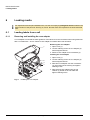
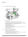
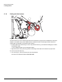
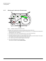
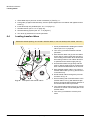
1
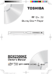
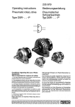
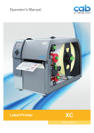
Transfer Printer BP-PR PLUS series Operating Instructions Edition 7/06 BP-PR PLUS series Information on the scope of delivery, appearance, performance, dimensions and weight reflect our knowledge at the time of printing. We reserve the right to make modifications. All rights, including those regarding the translation, are reserved. Approval The transfer printers comply with the following safety guidelines: CE EC Low-Voltage Directive (73/23/EEC) EC Machine Directive (98/37/EC) EC Electromagnetic Compatibility Directive (89/336/EEC) FCC Conditions from Part 15 of the FCC Regulations for Class A computing devices. Operation of this device may cause radio or television interference under unfavorable conditions, which would need to be remedied by the operator using countermeasures. W.H. Brady Lindestraat 21 Industriepark C3 9240 Zele Belgium Tel.: +32 52 457 811 e-mail: [email protected] 2 Identification Solutions Division 6555 W. Good Hope Road PO Box 2131 Milwaukee, WI 53201 U.S.A. Phone: 1-800-537-8791 Fax: 1-800-292-2289 Operating Instructions Edition 7/06 BP-PR PLUS series Table of contents 1 1.1 1.2 1.3 2 2.1 2.2 2.3 3 3.1 3.2 3.3 3.4 4 4.1 4.2 5 5.1 5.2 6 6.1 6.2 6.3 6.4 6.5 6.6 6.7 7 7.1 7.2 7.3 7.4 8 8.1 8.2 8.3 8.4 8.5 8.6 8.7 8.8 9 9.1 9.2 9.3 Edition 7/06 Notes on the documentation. . . . . . . . . . . . . . . . . . . . . . . . . . . . . . . . . . . . . . . . . 5 Structure of the documentation and navigation . . . . . . . . . . . . . . . . . . . . . . . . . . . . . . . . 5 Warnings, notes and other identifying markings . . . . . . . . . . . . . . . . . . . . . . . . . . . . . . . 5 Cross references and references to graphics, tables and documents. . . . . . . . . . . . . . . 6 Safety and the environment . . . . . . . . . . . . . . . . . . . . . . . . . . . . . . . . . . . . . . . . . 7 Intended use . . . . . . . . . . . . . . . . . . . . . . . . . . . . . . . . . . . . . . . . . . . . . . . . . . . . . . . . . . 7 Safety notes. . . . . . . . . . . . . . . . . . . . . . . . . . . . . . . . . . . . . . . . . . . . . . . . . . . . . . . . . . . 7 Environmentally-friendly disposal . . . . . . . . . . . . . . . . . . . . . . . . . . . . . . . . . . . . . . . . . . 8 Installation . . . . . . . . . . . . . . . . . . . . . . . . . . . . . . . . . . . . . . . . . . . . . . . . . . . . . . . 9 Unpacking the transfer printer . . . . . . . . . . . . . . . . . . . . . . . . . . . . . . . . . . . . . . . . . . . . . 9 Setting up the transfer printer . . . . . . . . . . . . . . . . . . . . . . . . . . . . . . . . . . . . . . . . . . . . . 9 Connecting the transfer printer . . . . . . . . . . . . . . . . . . . . . . . . . . . . . . . . . . . . . . . . . . . 10 Switching the transfer printer on and off . . . . . . . . . . . . . . . . . . . . . . . . . . . . . . . . . . . . 10 Operating panel . . . . . . . . . . . . . . . . . . . . . . . . . . . . . . . . . . . . . . . . . . . . . . . . . . 11 Layout of the operating panel . . . . . . . . . . . . . . . . . . . . . . . . . . . . . . . . . . . . . . . . . . . . 11 Functions of the operating panel during printing . . . . . . . . . . . . . . . . . . . . . . . . . . . . . . 12 Device types . . . . . . . . . . . . . . . . . . . . . . . . . . . . . . . . . . . . . . . . . . . . . . . . . . . . . 15 Standard device. . . . . . . . . . . . . . . . . . . . . . . . . . . . . . . . . . . . . . . . . . . . . . . . . . . . . . . 15 Peel-off device version . . . . . . . . . . . . . . . . . . . . . . . . . . . . . . . . . . . . . . . . . . . . . . . . . 15 Loading media . . . . . . . . . . . . . . . . . . . . . . . . . . . . . . . . . . . . . . . . . . . . . . . . . . . 16 Loading labels from a roll . . . . . . . . . . . . . . . . . . . . . . . . . . . . . . . . . . . . . . . . . . . . . . . Removing the wound roll . . . . . . . . . . . . . . . . . . . . . . . . . . . . . . . . . . . . . . . . . . . . . . . . Loading fanfold labels . . . . . . . . . . . . . . . . . . . . . . . . . . . . . . . . . . . . . . . . . . . . . . . . . . Loading transfer ribbon . . . . . . . . . . . . . . . . . . . . . . . . . . . . . . . . . . . . . . . . . . . . . . . . . Setting the feed path of the transfer ribbon . . . . . . . . . . . . . . . . . . . . . . . . . . . . . . . . . . Removing and installing the rewind guide plate, dispense plate or tear-off plate . . . . . Removing and installing the locking system . . . . . . . . . . . . . . . . . . . . . . . . . . . . . . . . . 16 22 22 23 24 24 25 Printing . . . . . . . . . . . . . . . . . . . . . . . . . . . . . . . . . . . . . . . . . . . . . . . . . . . . . . . . . 26 Synchronization . . . . . . . . . . . . . . . . . . . . . . . . . . . . . . . . . . . . . . . . . . . . . . . . . . . . . . . Tear-Off mode . . . . . . . . . . . . . . . . . . . . . . . . . . . . . . . . . . . . . . . . . . . . . . . . . . . . . . . . Peel-Off mode . . . . . . . . . . . . . . . . . . . . . . . . . . . . . . . . . . . . . . . . . . . . . . . . . . . . . . . . Internal rewinding . . . . . . . . . . . . . . . . . . . . . . . . . . . . . . . . . . . . . . . . . . . . . . . . . . . . . 26 26 26 26 Cleaning and basic maintenance . . . . . . . . . . . . . . . . . . . . . . . . . . . . . . . . . . . 27 Maintenance plan . . . . . . . . . . . . . . . . . . . . . . . . . . . . . . . . . . . . . . . . . . . . . . . . . . . . . Tools and cleaning agents. . . . . . . . . . . . . . . . . . . . . . . . . . . . . . . . . . . . . . . . . . . . . . . General cleaning . . . . . . . . . . . . . . . . . . . . . . . . . . . . . . . . . . . . . . . . . . . . . . . . . . . . . Cleaning the print roller . . . . . . . . . . . . . . . . . . . . . . . . . . . . . . . . . . . . . . . . . . . . . . . . Cleaning the printhead . . . . . . . . . . . . . . . . . . . . . . . . . . . . . . . . . . . . . . . . . . . . . . . . . Cleaning the label sensor . . . . . . . . . . . . . . . . . . . . . . . . . . . . . . . . . . . . . . . . . . . . . . . Replacing the printhead . . . . . . . . . . . . . . . . . . . . . . . . . . . . . . . . . . . . . . . . . . . . . . . . Replacing the print roller and rewind assist roller . . . . . . . . . . . . . . . . . . . . . . . . . . . . . 27 27 28 28 28 29 30 32 Error treatment . . . . . . . . . . . . . . . . . . . . . . . . . . . . . . . . . . . . . . . . . . . . . . . . . . . 33 Error types . . . . . . . . . . . . . . . . . . . . . . . . . . . . . . . . . . . . . . . . . . . . . . . . . . . . . . . . . . . 33 Troubleshooting . . . . . . . . . . . . . . . . . . . . . . . . . . . . . . . . . . . . . . . . . . . . . . . . . . . . . . . 34 Error messages and recovery . . . . . . . . . . . . . . . . . . . . . . . . . . . . . . . . . . . . . . . . . . . . 35 Operating Instructions 3 BP-PR PLUS series 10 EC Declaration of Conformity. . . . . . . . . . . . . . . . . . . . . . . . . . . . . . . . . . . . . . . 38 Index . . . . . . . . . . . . . . . . . . . . . . . . . . . . . . . . . . . . . . . . . . . . . . . . . . . . . . . . . . . 39 4 Operating Instructions Edition 7/06 BP-PR PLUS series Notes on the documentation 1 Notes on the documentation 1.1 Structure of the documentation and navigation The documentation for the transfer printers of the BP-PR PLUS series is comprised of the following parts: • Operating Instructions This is included in printed form in the scope of delivery and is directed toward persons who operate the transfer printer and perform basic maintenance and service work on the printer. • Configuration Instructions The are directed toward persons who set up, configure and perform more extensive maintenance and service work on the transfer printer. • Service Instructions These are directed toward trained service personnel who maintain and repair the transfer printer. Each set of instructions has its own page and chapter enumeration. For improved navigation through the document, the chapter titles are printed in the header. Additional navigation aids include the table of contents and the index. The PDF version also features bookmarks and hypertext links in the table of contents and the index. Additional documentation Spare parts lists Spare parts Programming manual Programming the transfer printer with the printerspecific command set Tab. 1: Additional documentation 1.2 Warnings, notes and other identifying markings 1.2.1 Warnings Warnings are presented with three signal words for the different levels of danger. The signal word DANGER identifies an extraordinarily great and immediate danger which could lead to serious injury or even death. The signal word WARNING identifies a possible danger would could lead to serious bodily injury or even death if sufficient precautions are not taken. The signal word CAUTION indicates a potentially dangerous situation which could lead to moderate or light bodily injury or damage to property. Warnings are always identified with a warning symbol (yellow triangle) and the signal word and specify the source of the danger, possible consequences and measures for avoiding the danger. Here’s an example: DANGER! Risk of death via electric shock! ⇒ Before opening the housing cover, disconnect the device from the mains supply and wait a few minutes until the power supply unit has discharged. Edition 7/06 Operating Instructions 5 BP-PR PLUS series Notes on the documentation 1.2.2 Notes Important information is identified with an exclamation mark on the left-hand side of the page. Information is identified with an "i" on the left-hand side of the page. 1.2.3 Display texts on the printer screen All texts appearing on the printer screen are identified in a special way e.g.: Timezone > UTC+1. This abbreviated statement instructs the user to select the Timezone menu and then the UTC+1 option in this menu. 1.3 Cross references and references to graphics, tables and documents 1.3.1 Item numbers Item numbers in the text are identified with parentheses, e.g. (9). If no figure number is provided, item numbers in the text always refer to the graphic directly above the text. If a reference is made to another graphic, the figure number is specified, e.g. Fig. 5 (1). 1.3.2 Cross references to chapters and sections With a cross reference to chapters and sections, the chapter number and page number are specified, e.g. a reference to this section: (see ”1.3.2” on page 6). 1.3.3 References to other documents References to other documents have the following form: See “Configuration Instructions“. All documents referred to in these instructions are listed in the section entitled "Structure of the documentation and navigation". (see ”1.1” on page 5). 6 Operating Instructions Edition 7/06 BP-PR PLUS series Safety and the environment 2 Safety and the environment Read these operating instructions carefully before using the transfer printer for the first time. The operating instructions describe all of the functions of the transfer printer during operation. The available functions depend on the version used for a specific job. A detailed product description with all the technical data can be found in the “Configuration Instructions for the BP-PR PLUS series“. 2.1 Intended use • The transfer printer is a state-of-the-art device which complies with the recognized safety-related rules and regulations. Despite this, a danger to life and limb of the user or third parties could arise and the transfer printer or other property could be damaged while operating the device. • The transfer printer may only be used while in proper working order and for the intended purpose. Users must be safe, aware of potential dangers and must comply with the operating instructions! Faults, in particular those which affect safety, must be remedied immediately. • The transfer printer is solely intended to print suitable media which have been approved by the manufacturer. Any other or additional use is not intended. The manufacturer/supplier is not liable for damage resulting from misuse. Any misuse is at your own risk. • Intended use includes heeding the operating instructions, including the maintenance recommendations/regulations specified by the manufacturer. 2.2 Safety notes • The transfer printer is designed for power supply systems from 100 V AC to 240 V AC. Connect the transfer printer only to electrical outlets with a ground contact. • Couple the transfer printer to devices using extra low voltage only. • Before making or undoing connections, switch off all devices involved (computer, printer, accessories etc.). • Operate the transfer printer in a dry environment only and do not get it wet (sprayed water, mist etc.). • If the transfer printer is operated with the cover open, ensure that clothing, hair, jewelry and similar personal items do not contact the exposed rotating parts. • The print mechanism can become hot during printing. Do not touch it during operation and allow it to cool down before changing the media or before removal or adjustment. • Carry out only the actions described in these operating instructions. Other tasks may only be performed by trained personnel or service technicians. DANGER! Risk of death via mains voltage! ⇒ Do not open the housing of the transfer printer. Edition 7/06 Operating Instructions 7 BP-PR PLUS series Safety and the environment 2.3 Environmentally-friendly disposal Used devices contain valuable recyclable materials which should be utilized. ⇒ Dispose of used devices separately from other waste, i.e. via an appropriate collection site. The modular nature of the transfer printer allows it to easily be disassembled into its component parts so that the parts can be turned in for recycling. The PCB of the transfer printer has a lithium battery. ⇒ Dispose of this battery in a collection container for old batteries at the store or with the public waste disposal authority. 8 Operating Instructions Edition 7/06 BP-PR PLUS series Installation 3 Installation 3.1 Unpacking the transfer printer ⇒ Lift the transfer printer out of the box via the straps. ⇒ Check transfer printer for damage which may have occurred during transport. ⇒ Check delivery for completeness. Scope of delivery • Transfer printer • Dispense plate (peel-off device ver- • Empty cardboard core, mounted on ribbon take-up hub • Tear-off plate (basic devices only) sion only) • Power cable • Documentation Retain the original packaging for subsequent transport. 3.2 Setting up the transfer printer CAUTION! The device and the print media can be damaged by moisture and water. ⇒ The transfer printer may only be set up in a dry place protected from sprayed water. ⇒ Set up printer on a level surface. 1 ⇒ Open cover (1) of the transfer printer. ⇒ Remove foam transportation safeguards near the printhead (2). 2 Fig. 1: Edition 7/06 Removing the transportation safeguards Operating Instructions 9 BP-PR PLUS series Installation 3.3 Connecting the transfer printer 1 2 3 4 5 6 7 8 1 2 3 4 Power switch Power connection jack Slot for Cardbus or a Type II PC card Slot for a CompactFlash memory card Ethernet 10/100 Base-T USB port for a keyboard or scanner USB high-speed slave port Serial RS 232 C port 5 6 7 8 Fig. 2: 3.3.1 Power and computer connections Connecting to the power supply The printer is equipped with a versatile power supply unit. The device may be operated with a mains voltage of 230 V AC/ 50 Hz or 115 V AC/60 Hz without any adjustments or modifications. CAUTION! The device can be damaged by undefined switch-on currents. ⇒ Set the power switch (1) to "O" before plugging in the device. 1. Insert power cable into power connection jack (2). 2. Insert plug of the power cable into a grounded electrical outlet. 3.3.2 Connecting to a computer or computer network Insufficient or missing grounding can cause faults during operation. Ensure that all computers and connection cables connected to the transfer printer are grounded. ⇒ Connect transfer printer to computer or network with a suitable cable. Details on the configuration of the individual interfaces are found in the “Configuration Instructions“. 3.4 Switching the transfer printer on and off Once all connections have been made: ⇒ Switch printer on via the power switch (1). The printer runs through a system test and then indicates the system status Ready in the display. If an error has occurred while the system was starting up, the (see ”4.2.8” on page 14). 10 Operating Instructions symbol and the error type are displayed Edition 7/06 BP-PR PLUS series Operating panel 4 Operating panel The user can control the operation of the printer with the operating panel, for example: • pause, continue or cancel print jobs • set printing parameters, e.g. heating energy of the printhead, print speed, configuration of the ports, language and time (see “Configuration Instructions“) • start test functions (see “Configuration Instructions“) • control standalone operation with memory card (see “Configuration Instructions“) • perform a firmware update (see “Configuration Instructions“) Several functions and settings can also be controlled via printer-specific commands with software applications or via direct programming with a computer. Details on this can be found in the “Configuration Instructions“. The settings made at the operating panel are the basic settings of the transfer printer. It is to your advantage to make adjustments for different print jobs in the software whenever possible. 4.1 Layout of the operating panel The operating panel is comprised of the graphical display (1) and the navigator pad (2) with five integrated buttons. The graphical display informs you of the current status of the printer and the print job, reports errors and shows the printer settings in the menu. 1 The button functions are dependent on the current printer status: Active functions are indicated by the illuminated letters and symbols on the buttons of the navigator pad. 2 While printing, active functions illuminate white (e.g. menu or feed) Active functions are illuminated in orange in the offline menu (arrows, ↵ button) Functions of the buttons Fig. 3: Operating panel pause, cancel, menu, reed buttons: (see ”4.2.3” on page 13) Arrows: Up, down, left and right in the menu tree. ↵ button: Input of a parameter in the menu, calling up of help in case of an error Edition 7/06 Operating Instructions 11 BP-PR PLUS series Operating panel 4.2 Functions of the operating panel during printing 4.2.1 Symbol indicators The symbol indicators shown in the following table can appear on the status line of the screen, depending on the configuration of the printer. They inform you of the current status of the printer at a glance. For configuration of the status line, see the “Configuration Instructions“. Symbol Meaning Time Date Ribbon supply status WLAN field strength Ethernet status Printhead temperature PPP credit User memory Input buffer Printer receiving data Tab. 2: Indicator symbols during printing 4.2.2 Power-Save mode If the printer is not used for some time, it switches to Power-Save mode automatically. The display shows the graphic and button illumination is switched off. To exit Power-Save mode: ⇒ Press any button on the navigator pad. 12 Operating Instructions Edition 7/06 BP-PR PLUS series Operating panel 4.2.3 'Ready' mode The printer is ready and can receive data. The display shows the text Ready and the configured symbol indicators, such as the time . and date Button Label Function menu illuminates go to offline menu (see “Configuration Instructions“) feed illuminates advances an empty label pause illuminates once a print job is complete repeat printing of last label cancel illuminates clear print buffer, repeated printing of the last label is then not possible Tab. 3: Functions in Ready mode 4.2.4 'Printing Label' mode The printer is carrying out a print job. Data transfer for a new print job is possible in 'Printing' mode. The new print job starts once the preceding job is completed. The display shows the text Printing Label and the number of the printed label within the print job. Button Label Function pause illuminates pause print job, printer switches to Pause mode cancel illuminates press briefly→ cancel current print job press and hold→ cancel current print job and delete all print jobs Tab. 4: Functions in Printing Label mode 4.2.5 'Pause' mode The print job has been interrupted by the operator. The display shows the text Pause and the symbol . Button Label Function pause illuminates continue print job, printer switches to Printing Label mode cancel illuminates press briefly→ cancel current print job press and hold→ cancel current print job and delete all print jobs Tab. 5: Functions in Pause mode Edition 7/06 Operating Instructions 13 BP-PR PLUS series Operating panel 4.2.6 'Fault - correctable' mode An error which can be remedied by the operator without canceling the print job has occurred. The print job can be continued once the error is remedied. The display shows the symbol , the error type and the number of labels still to be printed. Button Label Function pause flashes continue print job after error recovery, printer switches to Printing Label mode cancel illuminates press briefly→ cancel current print job press and hold→ cancel current print job and delete all print jobs ↵ button illuminates call up help – brief information on error recovery is displayed Tab. 6: Functions in 'error which can be remedied' mode 4.2.7 'Fault - irrecoverable' mode An error which cannot be remedied without canceling the print job has occurred. The display shows the symbol , the error type and the number of labels still to be printed. Button Label Function cancel flashes press briefly→ cancel current print job press and hold→ cancel current print job and delete all print jobs ↵ button illuminates call up help – brief information on error recovery is displayed Tab. 7: Functions in 'error which cannot be remedied' mode 4.2.8 'System error' mode If an error has occurred while the system was starting up, the symbol and the error type are displayed. ⇒ Switch off printer via the power switch and switch it on again. -or⇒ Push the cancel button. ⇒ If the error occurs repeatedly, notify the Service Department. 14 Operating Instructions Edition 7/06 BP-PR PLUS series Device types 5 Device types 5.1 Standard device The standard device is used for printing labels or continuous media on rolls or fanfolded media. In Tear-Off mode, labels are removed by hand. The labels can be cut off automatically with the 'cutter' accessory. For details, see the Operating Instructions for the 'cutter' accessory. The labels can be wound up with the 'external rewinder' accessory. For details, see the Operating Instructions for the 'external rewinder' accessory. Because there is no internal rewinder, automatic peeling off of the labels from the carrier medium (PeelOff mode) and internal rewinding are not possible. 5.2 Peel-off device version The peel-off device version is capable of Peel-Off mode and thus has an internal rewinder and a pulling system comprised of a rewind assist roller and a locking system. Printing on labels or continuous media from rolls or fanfolded media is possible. Operation in Tear-Off mode and with the 'cutter' or 'external rewinder' accessory is possible by installing the tear-off plate (see ”6.6” on page 24), as with the standard device. In Peel-Off mode, the label is peeled off the liner after printing. The label can be removed by hand with the peel-off sensor (accessory). Label removal can also occur automatically via the applicator (accessory). The liner is rolled up via the internal rewinder. For use in Internal Rewind mode remove the locking system (see ”6.7” on page 25) and replace the dispense plate with a rewind guide plate (see ”6.6” on page 24). Edition 7/06 Operating Instructions 15 BP-PR PLUS series Loading media 6 Loading media For adjustments and simple installation work, use the accompanying hexagonal wrench located in the bottom section of the print unit. See Fig. 5, Item 8. No other tools are required for the work described here. 6.1 Loading labels from a roll 6.1.1 Removing and installing the core adapter A core adapter is mounted for better guidance of the label roll on the roll retainer when using label rolls with a core diameter ≥ 75 mm. Remove core adapter for smaller label rolls as follows. Removing the core adapter 1 1. Open cover (1). 2. Loosen retaining screws of core adapter (2) with hexagonal wrench. 3. Remove core adapter from roll retainer (4). Installing the core adapter 1. Open cover (1). 2 2. Loosen retaining screws of core adapter (2) with hexagonal wrench. 3 4 3. Slide first core adapter onto the roll retainer (4) until it stops at the housing and tighten retaining screw. 4. Slide second core adapter onto the roll retainer (4) based on the roll width and tighten retaining screw. Fig. 4: 16 Installing the core adapter Operating Instructions Edition 7/06 BP-PR PLUS series Loading media 6.1.2 Positioning the label roll on the roll retainer 1 2 10 9 3 4 8 Fig. 5: 7 6 5 Loading labels from a roll 1. Open cover (10). 2. Loosen knurled screw (1) and swivel guide (2) upward and push it all the way out. 3. Remove core adapter (4) for label rolls with a core diameter ≤ 75 mm (see ”6.1.1” on page 16). 4. Load label roll on the roll retainer in such a way that the labels can be inserted into the printhead in the right position. The printing side of the labels must be visible from above. 5. Supplying longer label strips: For Peel-Off or Rewind mode: approx. 60 cm For Tear-Off mode: approx. 40 cm 6. Push label roll until it contacts the housing wall. 7. Swivel guide (2) downward onto the roll retainer (3) and push it against the label roll so that the roll is braked slightly while supplying media. 8. Tighten knurled screw (1). 6.1.3 Inserting a label strip into the printhead 1. Turn lever (9) counterclockwise to lift the printhead. 2. Push guide ring on axis (6) all the way out. 3. Guide label strip to the print unit above the internal rewinder (5). 4. Guide label strips below the axis (6) and through the label sensor (7) in such a way that it exits the print unit between the printhead and the print roller. 5. Push guide ring on axis (6) against the outer edge of the label strip. Edition 7/06 Operating Instructions 17 BP-PR PLUS series Loading media 6.1.4 Setting the label sensor 1 2 3 Fig. 6: Setting the label sensor The label sensor (2) can be shifted perpendicular to the direction of paper flow for adaptation to the label medium. The sensor unit (1) of the label sensor is visible from the front through the print unit and is marked with a indentation in the label sensor retainer. ⇒ Position label sensor with tab (3) in such a way that the sensor (1) can detect the label gap or a reflex or perforation mark. - or, if the labels deviate from a rectangular shape, ⇒ Align label sensor using the tab (3) with the front edge of the label in the direction of paper flow. For use in Tear-Off mode only: ⇒ Turn lever (Fig. 5, Item 9) clockwise to lock the printhead. The label roll is loaded for use in Tear-Off mode. 18 Operating Instructions Edition 7/06 BP-PR PLUS series Loading media 6.1.5 Winding up the label strip in Rewind mode 5 4 3 2 1 Fig. 7: Guiding the label strip in Rewind mode In Rewind mode, the labels are wound up internally after printing for later use. 1. Remove the locking system for Rewind mode if necessary (see ”6.7” on page 25) and install rewind guide plate (see ”6.6” on page 24). 2. Guide label strip around the rewind guide plate (4) to the internal rewinder (2). 3. Hold rewinder (2) firmly and turn knob (3) clockwise until it stops. 4. Push label strip under a bracket (1) of the rewinder and turn knob (3) counterclockwise until it stops. The rewinder is fully spread, thus gripping the label strip firmly. 5. Turn rewinder (2) counterclockwise to tighten the label strip. 6. Turn lever (5) clockwise to lock the printhead. The label roll is loaded for use in Rewind mode. Edition 7/06 Operating Instructions 19 BP-PR PLUS series Loading media 6.1.6 Winding up the liner in Peel-Off mode 7 6 5 4 Fig. 8: 3 2 1 Guidance of the liner in Peel-Off mode In Peel-Off mode, the labels are removed after printing, and only the liner is wound up internally. 1. Lift the pinch roller (4) off the rewind assist roller (5). 2. Remove labels from the first 100 mm of the liner. 3. Guide liner to the rewinder (2) around the dispense plate (6) and the rewind assist roller (5). 4. Hold rewinder (2) firmly and turn knob (3) clockwise until it stops. 5. Push liner under a bracket (1) of the rewinder (2) and turn knob (3) counterclockwise until it stops. The rewinder is fully spread, thus gripping the liner firmly. 6. Turn rewinder (2) counterclockwise to tighten the liner. 7. Slightly loosen top fixing screw at the locking system with hexagonal wrench and position the pinch roller (4) centrally to the liner (see ”6.7” on page 25). 8. Close the locking system and tighten top fixing screw at the locking system. 9. Turn lever (7) clockwise to lock the printhead. The label roll is loaded for use in Peel-Off mode. 20 Operating Instructions Edition 7/06 BP-PR PLUS series Loading media 6.1.7 Setting the head locking system The printhead is pushed on via two plungers. The location of the outer plunger must be set to the width of the label medium used so as to • achieve even print quality across the entire label width • prevent wrinkles in the feed path of the transfer ribbon • prevent premature wearing of the print roller and printhead. 1 2 3 Fig. 9: Setting the head locking system 1. Turn lever (3) clockwise to lock the printhead. 2. Loosen threaded pin (1) at outer plunger (2) with hexagonal wrench. 3. Position outer plunger (2) above the outer label edge and tighten threaded pin (1). Edition 7/06 Operating Instructions 21 BP-PR PLUS series Loading media 6.2 Removing the wound roll 7 6 5 4 3 2 1 Fig. 10: Removing the wound roll 1. Turn lever (7) counterclockwise to lift the printhead. 2. Cut label strip and wind it fully around the rewinder (2). 3. Hold rewinder (2) firmly and turn knob (3) clockwise. The rewinder spindle relaxes and the wound roll is released. 4. Remove wound roll from rewinder (2). 6.3 Loading fanfold labels 1 2 5 3 4 Fig. 11: Feed path of paper with fanfold labels 1. Loosen knurled screw (1) and slide guide (2) outward completely and swivel it downward past the roll retainer (3). 2. If core adapters are mounted on the roll retainer (3), remove core adapters (see ”6.1.1” on page 16). 3. Position label stack (4) behind the printer. Ensure that the labels on the strip are visible from above. 22 Operating Instructions Edition 7/06 BP-PR PLUS series Loading media 4. Guide label strip to print unit via the roll retainer (3). See Fig. 11. 5. Push guide (2) against the label strip, swivel it upward against the roll retainer and tighten knurled screw (1). 6. Insert label strip into printhead (see ”6.1.3” on page 17). 7. Set label sensor (see ”6.1.4” on page 18). 8. Set head locking system (see ”6.1.7” on page 21) 9. Turn lever (5) clockwise to lock the printhead. 6.4 Loading transfer ribbon With direct thermal printing, do not load a transfer ribbon; if one has already been loaded, remove it. 1 2 3 1. Clean printhead before loading the transfer ribbon (see ”8.5” on page 28). 2. Turn lever (4) counterclockwise to lift the printhead. 3. Slide transfer ribbon roll (2) onto the ribbon supply hub (3) until it stops and so that the color coating of the ribbon faces downward when being unwound. No rotation direction is specified for the ribbon supply hub (3). 4. Hold transfer ribbon roll (2) firmly and turn knob on ribbon supply hub (3) counterclockwise until the transfer ribbon roll is secured. 4 5. Slide suitable transfer ribbon core onto the transfer ribbon take-up hub (1) and secure it in the same way. 6. Guide transfer ribbon through the print unit as shown in Fig. 12. Fig. 12: Feed path of the transfer ribbon 7. Secure starting end of transfer ribbon to the transfer ribbon core (1) with adhesive tape. Ensure counterclockwise rotation direction of the transfer ribbon take-up hub here. 8. Turn transfer ribbon take-up hub (1) counterclockwise to smooth out the feed path of the transfer ribbon. 9. Turn lever (4) clockwise to lock the printhead. Edition 7/06 Operating Instructions 23 BP-PR PLUS series Loading media 6.5 Setting the feed path of the transfer ribbon Transfer ribbon wrinkling can lead to print image errors. Transfer ribbon deflection can be adjusted so as to prevent wrinkles. See also “Setting the head locking system” on page 21. The adjustment is best carried out during printing. 1. Read current setting on the scale (1) and record if necessary. 1 2. Turn screw (2) with hexagonal wrench and observe the behavior of the ribbon. In the + direction, the inner edge of the transfer ribbon is tightened, and the outer edge is tightened in the - direction. 2 Fig. 13: Setting the feed path of the transfer ribbon 6.6 Removing and installing the rewind guide plate, dispense plate or tear-off plate To convert the printer for use in another operating mode, a rewind guide plate, a dispense plate or a tearoff plate may need to be installed. For printer versions with a locking system on the rewind assist roller, the locking system on the rewind assist roller must be removed (see ”6.7” on page 25) for operation in Rewind mode before installation of the rewind guide plate. Removing a plate 1. Loosen screws (2) several turns. 2. Slide plate (1) to the right and remove it. Installing a plate 1. Place plate (1) onto the screws (2) and slide to the left completely. 2. Tighten screws (2). 2 1 2 Fig. 14: Removing and installing the rewind guide plate, dispense plate or tear-off plate 24 Operating Instructions Edition 7/06 BP-PR PLUS series Loading media 6.7 Removing and installing the locking system Removing the locking system 1. Position printer at edge of table so that the oblong hole is accessible from below. 2. Screw out screws (1) (2) and remove them. 3. Remove the pinch roller (4) and bottom plate (3). 1 Installing the locking system 1. Position printer at edge of table so that the oblong hole is accessible from below. 2. Place the pinch roller (4) into oblong hole and lightly tighten screw (1) of bottom plate (3) from above. 4 3 3. Lightly tighten screw (2) of bottom plate (3) from below. 2 4. Align the pinch roller (4) with center of label and tighten screws. Fig. 15: Removing the locking system Edition 7/06 Operating Instructions 25 BP-PR PLUS series Printing 7 Printing CAUTION! The printhead can be damaged if handled improperly! ⇒ Do not touch the bottom of the printhead with your fingers or sharp objects. ⇒ Ensure that the labels are clean. ⇒ Ensure smooth label surfaces. Raw labels are like emery and reduce the service life of the printhead. ⇒ Print at the lowest possible printhead temperature. 7.1 Synchronization The printer is ready for operation when all connections have been made, the labels and, if necessary the transfer ribbon, have been loaded and the printhead is locked. For details on printer configuration, see the “Configuration Instructions“. After loading the label medium, synchronization is necessary. During synchronization, the printer automatically determines the length of the loaded labels and sets label advancement accordingly. 1. Press the feed button to start synchronization. 2. Remove empty labels after synchronization. The printer is synchronized with the loaded label medium. Synchronization is not necessary if the printhead was not opened between different print jobs, even if the printer was switched off. 7.2 Tear-Off mode In Tear-Off mode, labels or continuous media are printed. After printing, the label strip is separated by hand. The transfer printer is equipped with a tear-off plate for this. Optionally, the label can be cut off or label strips can be wound up externally. 7.3 Peel-Off mode In Peel-Off mode, the labels are automatically peeled off the carrier medium after printing and presented for removal. The transfer printer is equipped with a dispense plate and one of the following accessory devices for this: peel-off sensor (PS6 or PS8), peel-off adapter (PS5) or applicator (A1000). The carrier medium is wound up inside the printer. 7.4 Internal rewinding The labels are wound up internally after printing with the carrier medium for later use. The transfer printer is equipped with a rewind guide plate for this. 26 Operating Instructions Edition 7/06 BP-PR PLUS series Cleaning and basic maintenance 8 Cleaning and basic maintenance DANGER! Risk of death via electric shock! ⇒ Disconnect the printer from the power supply before performing any maintenance work. 8.1 Maintenance plan Maintenance task When General cleaning (see ”8.3” on page 28) as necessary Clean print roller (see ”8.4” on page 28) each time the label roll is changed or when the print image and label transport are adversely affected. Clean printhead (see ”8.5” on page 28) direct thermal printing: each time the label roll is changed thermal transfer printing: each time the transfer ribbon is changed or when the print image is adversely affected Clean label sensor (see ”8.6” on page 29) when the label roll is changed Replace printhead (see ”8.7” on page 30) when errors in the print image occur Replace print roller and rewind assist roller (see ”8.8” on page 32) when print image and label transport are adversely affected Tab. 8: Maintenance plan 8.2 Tools and cleaning agents For adjustments and simple installation work, use the accompanying hexagonal wrench located in the bottom section of the print unit. See Fig. 5, Item 8. No other tools are required for the work described here. Cleaning agents • soft brush • roller cleaner Edition 7/06 • soft cloth • cotton swabs Operating Instructions • pure alcohol • special cleaning pen 27 BP-PR PLUS series Cleaning and basic maintenance 8.3 General cleaning CAUTION! Abrasive cleaning agents can damage the printer! ⇒ Do not use abrasives or solvents to clean the outer surfaces or assemblies. ⇒ Remove dust and paper fuzz in the printing area with a soft brush or vacuum cleaner. ⇒ Clean outer surfaces with an all-purpose cleaner. 8.4 Cleaning the print roller 1. Turn lever (4, Fig. 12) counterclockwise to lift the printhead. 2. Remove labels and transfer ribbon from the printer. 3. Remove deposits with roller cleaner and a soft cloth. 4. If the roller appears damaged, replace it (see ”8.8” on page 32). 8.5 Cleaning the printhead Substances may accumulate on the printhead during printing and adversely affect printing, e.g. differences in contrast or vertical stripes. CAUTION! Printhead can be damaged! ⇒ Do not use sharp or hard objects to clean the printhead. ⇒ Do not touch protective glass layer of the printhead. 1. Turn lever (4, Fig. 12) counterclockwise to lift the printhead. 2. Remove labels and transfer ribbon from the printer. 3. Clean printhead surface with special cleaning pen or a cotton swab dipped in pure alcohol. 4. Allow printhead to dry for 2–3 minutes before commissioning the printer. 28 Operating Instructions Edition 7/06 BP-PR PLUS series Cleaning and basic maintenance 8.6 Cleaning the label sensor CAUTION! Label sensor can be damaged! ⇒ Do not use sharp or hard objects or solvents to clean the label sensor. The label sensor can become dirtied with paper dust. This can adversely affect label detection. 1. Turn lever (1) counterclockwise to lift the printhead. 2. Remove labels and transfer ribbon from the printer. 3. Remove hexagonal wrench (5) from its retainer. 1 4. Press the latch (3) and slowly pull label sensor outward via the tab (4). Ensure that the label sensor cable is not tensioned by this. 2 3 5. Clean label sensor and sensor units (2) with brush or cotton swab soaked in pure alcohol. 6. Push label sensor back via tab (3) and set it (see ”6.1.4” on page 18). 5 4 7. Push hexagonal wrench (5) into retainer. 8. Reload labels and transfer ribbon (see ”6.1” on page 16). Fig. 16: Cleaning the label sensor Edition 7/06 Operating Instructions 29 BP-PR PLUS series Cleaning and basic maintenance 8.7 Replacing the printhead The printhead of the transfer printer can be replaced without the need for fine adjustment. The printhead must be replaced if worn or when switching to a printhead with higher or lower resolution. For better differentiation, the print heads have a label stating the printer type and resolution. 1 2 1 2 3 4 5 6 7 4 6 3 7 Head plate Plug connection Plug connection Screw Printing line Pins Printhead 6 4 5 Fig. 17: Structure of the printhead The printhead (7) is preinstalled on a head plate (1) and precisely aligned at the factory. Do not loosen the screws (4) under any circumstances. CAUTION! The printhead can be damaged by static electricity discharges and impacts! ⇒ Set up printer on a grounded, conductive surface. ⇒ Ground your body, e.g. by wearing a grounded wristband. ⇒ Do not touch contacts on the plug connections (2, 3). ⇒ Do not touch printing line (5) with hard objects or your hands. 30 Operating Instructions Edition 7/06 BP-PR PLUS series Cleaning and basic maintenance 8 9 10 2 4 1 7 4 6 11 6 5 3 Fig. 18: Removing and installing the printhead Removing the printhead 1. Turn lever (10) counterclockwise to lift the printhead. 2. Remove labels and transfer ribbon from the printer. 3. Remove hexagonal wrench (9) from its retainer. 4. Lightly keep printhead mounting bracket (9) on the print roller with one finger and screw out screw (8) with the hexagonal wrench and remove it and the washer. 5. Swivel printhead mounting bracket (9) upward. 6. Remove printhead from the printhead mounting bracket (9) if necessary. 7. Loosen both plug connections (2, 3) on the printhead and set printhead down on a clean, soft surface. Installing the printhead 1. Attach plug connections (2, 3). 2. Position printhead in printhead mounting bracket (9) in such a way that the pins (6) are secured in the corresponding holes in the printhead mounting bracket (9). 3. Lightly keep printhead mounting bracket (9) on the print roller with one finger and check for correct positioning of the printhead mounting bracket (9). 4. Screw in screw (8) with washer with the hexagonal wrench and tighten it. 5. Reload labels and transfer ribbon (see ”6.1” on page 16). Edition 7/06 Operating Instructions 31 BP-PR PLUS series Cleaning and basic maintenance 8.8 Replacing the print roller and rewind assist roller Removing the side plate 1. Turn lever (1) counterclockwise to lift the printhead. 2. Lift the pinch roller (5) off the rewind assist roller. 3. Remove labels and transfer ribbon from the printer. 4. Loosen screws (4) on plate (6) with hexagonal wrench by several turns and remove plate (6). 4 6 3a 5. Unscrew screws (3abc) of the side plate (2) with hexagonal wrench. 3b 2 6. Remove side plate (2). 3c 5 Fig. 19: Removing the side plate Removing and installing rollers 1. Pull print roller (7) and rewind assist roller (8) from the shafts (9, 10) on the housing. 2. Clean shafts (9, 10) of the rollers (see expanded view at shaft (10)). 3. Slide print roller (7) and rewind assist roller (8) onto their respective shafts and turn slightly until the hexagon of the shaft engages in the hexagon socket of the print roller. 1 4. Set side plate (Item 2, Fig. 19) in place and screw it down with the screws (Items 3abc, Fig. 19) by tightening the screws in order, i.e. a, b then c. 7 5. Set plate (Item 6, Fig. 19) in place and tighten screws (Item 4, Fig. 19) with hex8 agonal wrench. 10 9 Fig. 20: Removing and installing rollers 32 Operating Instructions Edition 7/06 BP-PR PLUS series Error treatment 9 Error treatment 9.1 Error types When an error occurs, the diagnostic system displays the error on the screen and switches the printer into one of the three possible error modes, depending on the error type: Symbol Navigator pad Error type pause flashes cancel illuminates Fault - correctable (see ”4.2.6” on page 14) cancel flashes Fault - irrecoverable (see ”4.2.7” on page 14) — System error (see ”4.2.8” on page 14) Tab. 9: Error modes Edition 7/06 Operating Instructions 33 BP-PR PLUS series Error treatment 9.2 Troubleshooting Problem Cause Solution Transfer ribbon wrinkles Transfer ribbon deflection not adjusted See “Setting the feed path of the transfer ribbon” on page 24. Head locking system not adjusted See “Setting the head locking system” on page 21. Transfer ribbon too wide Use only transfer ribbons which are just a bit wider than the label. Printhead dirty See “Cleaning the printhead” on page 28. Temperature too high Decrease temperature via software Unfavorable combination of labels and transfer ribbon Use another ribbon type or brand. Printer does not stop when transfer ribbon is done. Direct thermal printing is selected in the software Switch to thermal transfer printing in the software Printer prints a series of characters instead of the label format Printer is in Monitor mode Exit Monitor mode. Print image is blurred or missing in places Printer transports the label Transfer ribbon loaded incormedium, but not the trans- rectly fer ribbon. Check course of transfer ribbon and orientation of the covered side and correct if necessary. Unfavorable combination of labels and transfer ribbon Use another ribbon type or brand. Printer prints only every second label Format setting in software is too large. Change format setting in the software. Vertical white lines in print image Printhead dirty See “Cleaning the printhead” on page 28. Printhead defective (failure of dots) See “Replacing the printhead” on page 30. Printer is being operated in Cutting mode or Peel-Off mode with the setting Backfeed > smart Change setup to Backfeed > always. See “Configuration Instructions“ Horizontal white lines in print image Printing lighter on one side Printhead dirty Head locking system not adjusted See “Cleaning the printhead” on page 28. See “Setting the head locking system” on page 21. Tab. 10: Troubleshooting 34 Operating Instructions Edition 7/06 BP-PR PLUS series Error treatment 9.3 Edition 7/06 Error messages and recovery Error message Cause Error recovery ADC malfunction Hardware error Switch printer off and on again. If it occurs again → Service. Barcode error Invalid barcode contents, e.g. alphanumeric characters in numerical barcode Correct barcode contents. Barcode too big Barcode is too large for the allotted area of the label Shrink or shift barcode. Battery low Battery of the PC card is dead Replace battery in PC card. Buffer overflow Data input buffer is full, and the computer is attempting to send more data Use data transfer with protocol (preferably RTS/CTS). Card full Memory card cannot accept any more data Change memory card. Device not conn. Programming does not respond to existing device Connect an optional device or correct programming. File not found Calling up of a file from the memory card which does not exist Check contents of the memory card. Error in the selected download font Cancel print job, change font. FPGA malfunction Hardware error Switch printer off and on again. If it occurs again → Service. Head error Hardware error Switch printer off and on again. If it occurs again → replace printhead (see ”8.7” on page 30). Head open Printhead not locked Lock printhead. Head too hot Printhead excessively warm The print job continues automatically after pausing. If this occurs repeatedly, reduce the heat level or print speed in the software. Invalid setup Error in configuration memory Reconfigure printer. If it occurs again → Service. Memory overflow Print job too large: e.g. due to loaded fonts, large graphics Cancel print job. Reduce amount of data to be printed. Name exists Field name in direct programming entered twice Correct programming. No DHCP server Printer is configured for DHCP, and there is no DHCP server or the DHCP server is currently unavailable Deactivate DHCP in the configuration and issue a permanent IP address. Operating Instructions Notify the network administrator. 35 BP-PR PLUS series Error treatment Error message Cause Error recovery No label found Several labels are missing from the label strip Press the pause button several times until the next label on the strip is detected by the printer. The label format specified in the software does not match the actual format used Cancel print job. Change label format in the software. Restart print job. A continuous medium is located in the printer, but the software is waiting for labels Cancel print job. Change label format in the software. Restart print job. No label size Label size not defined in programming Check programming. No Link There is no network connection Check network cable and plug. No record found Error in the memory card option when accessing the database Check programming and memory card contents. No SMTP server Printer is configured for SMTP, and there is no SMTP server or the SMTP server is currently unavailable Deactivate SMTP in the configuration. Caution! Warnings via email (EAlert) can then no longer be received! Timeserver is selected in the configuration, but there is no timeserver or the timeserver is currently not available. Deactivate Timesaver in the configuration. Label roll used up Load a label roll (see ”6.1” on page 16) or No Timeserver Out of paper Notify the network administrator. Notify the network administrator. Notify the network administrator. Load fanfold labels (see ”6.3” on page 22). Out of ribbon 36 Error in paper course Check paper course. Transfer ribbon used up Load new transfer ribbon Transfer ribbon melted through during printing Cancel print job. Change heat level via software. Clean printhead (see ”8.5” on page 28). Load transfer ribbon (see ”6.4” on page 23). Restart print job. Thermal paper labels are to be used, but the software is set to transfer printing Cancel print job. Switch to direct thermal printing in the software. Restart print job. Supply roll of transfer ribbon not secured to ribbon supply hub Secure transfer ribbon (see ”6.4” on page 23). Operating Instructions Edition 7/06 BP-PR PLUS series Error treatment Error message Cause Error recovery Protocol error Printer receives an unknown or incorrect command from the computer. Press the pause button to skip the command or Press the cancel button to cancel the print job. Read error Read error when accessing memory card Check data on memory card. Structural err. Error in directory of the memory card, non-secure data access Reformat memory card. Unknown card Memory card not formatted Memory card type not supported Format card, use another card type. USB error Device stalled USB device is detected, but does not function Do not use USB device. USB error Too much current USB device drawing too much current Do not use USB device. USB error Unknown device USB device not recognized Do not use USB device. Voltage error Hardware error Switch printer off and on again. If it occurs again → Service. The voltage which has failed is displayed. Please note this. Write error Hardware error Repeat write attempt. Reformat card. Write protected Write protection of the PC card is activated. Deactivate write protection. Wrong revision Error when loading a new firmware version. Firmware does not work with hardware version Load appropriate firmware. Save data. Reformat card. Tab. 11: Error recovery Edition 7/06 Operating Instructions 37 BP-PR PLUS series EC Declaration of Conformity 10 EC Declaration of Conformity *HVHOOVFKDIWIU&RPSXWHU und Automations%DXVWHLQHPE+&R.* :LOKHOP6FKLFNDUG6WU '.DUOVUXKH EU Conformity Declaration We declare herewith that as a result of the manner in which the machine designated below was designed, the type of construction and the machines which, as a result have been brought on to the general market comply with the relevant fundamental regulations of the EU Rules for Safety and Health. In the event of any alteration which has not been approved by us being made to any machine as designated below, this statement shall thereby be made invalid. Description : Type : Transfer Printer / Thermal Direct Printer BP-PR PLUS series Applied EU Regulations and Norms: - EC Machinery Regulations - Machine Safety 98/37/EU EN ISO 12100-1:2003 EN ISO 12100-2:2003 - EC Low Voltage Regulations 'DWDDQG2I¿FH0DFKLQH6DIHW\ 73/23/EEC (1 - EC Electromagnetic Compatibility Regulations 7KUHVKROGYDOXHVIRUWKH,QWHUIHUHQFH of Data Machines /LPLWVIRUKDUPRQLFFXUUHQWHPLVVLRQ /LPLWVRIYROWDJHÀXFWXDWLRQDQGÀLFNHU ,PPXQLW\FKDUDFWHULVWLFV Limits and methods of measurement 89/336/EEC (1$$&ODVV$ (1 (1$ (1$$ Signed for, and on behalf of, the Manufacturer : cab Produkttechnik Sömmerda *HVHOOVFKDIWIU&RPSXWHU und Automationsbausteine mbH 6|PPHUGD 6|PPHUGD7 Erwin Fascher Managing Director 38 Operating Instructions Edition 7/06 BP-PR PLUS series Index Index C Cleaning . . . . . . . . . . . . . . . . . . . . . . . . . 27, Label sensor . . . . . . . . . . . . . . . . . . . . . Print roller . . . . . . . . . . . . . . . . . . . . . . . Printhead . . . . . . . . . . . . . . . . . . . . . . . . Cleaning agents . . . . . . . . . . . . . . . . . . . . . . Cleaning the label sensor . . . . . . . . . . . . . . Computer connection . . . . . . . . . . . . . . . . . . Connections . . . . . . . . . . . . . . . . . . . . . . . . . 28 29 28 28 27 29 10 10 D Device types . . . . . . . . . . . . . . . . . . . . . . . . 15 Display . . . . . . . . . . . . . . . . . . . . . . . . . . . . . 11 Disposal . . . . . . . . . . . . . . . . . . . . . . . . . . . . . 8 E Environment . . . . . . . . . . . . . . . . . . . . . . . . . . 8 Error Causes . . . . . . . . . . . . . . . . . . . . . . . . . 35 Messages . . . . . . . . . . . . . . . . . . . . . . . 35 Recovery . . . . . . . . . . . . . . . . . . . . . . . . 35 System . . . . . . . . . . . . . . . . . . . . . . . . . . 14 Treatment . . . . . . . . . . . . . . . . . . . . . . . 33 Types . . . . . . . . . . . . . . . . . . . . . . . . . . . 33 F Fault correctable . . . . . . . . . . . . . . . . . . . . . . . 14 irrecoverable . . . . . . . . . . . . . . . . . . . . . 14 Functions of the operating panel . . . . . . . . . 12 H Hexagonal wrench . . . . . . . . . . . . . . . . . . . . 16 I Inserting a label strip into the printhead . . . . 17 Installation . . . . . . . . . . . . . . . . . . . . . . . . . . . 9 Installing the printhead . . . . . . . . . . . . . . . . . 31 Internal rewinding . . . . . . . . . . . . . . . . . . . . . 26 L Lithium battery . . . . . . . . . . . . . . . . . . . . . . . . 8 Loading Fanfold labels . . . . . . . . . . . . . . . . . . . . 22 Labels . . . . . . . . . . . . . . . . . . . . . . . . . . 16 Labels from a roll . . . . . . . . . . . . . . . . . . 16 Media . . . . . . . . . . . . . . . . . . . . . . . . . . . 16 Ribbon . . . . . . . . . . . . . . . . . . . . . . . . . . 23 Transfer ribbon . . . . . . . . . . . . . . . . . . . 23 M Maintenance . . . . . . . . . . . . . . . . . . . . . . . . Maintenance plan . . . . . . . . . . . . . . . . . . . . . Mode Fault - correctable . . . . . . . . . . . . . . . . . Fault - irrecoverable . . . . . . . . . . . . . . . . Edition 7/06 27 27 14 14 Pause . . . . . . . . . . . . . . . . . . . . . . . . . . 13 Printing Label . . . . . . . . . . . . . . . . . . . . . 13 Ready . . . . . . . . . . . . . . . . . . . . . . . . . . 13 N Navigator pad . . . . . . . . . . . . . . . . . . . . . . . . 11 Network connection . . . . . . . . . . . . . . . . . . . 10 Notes on the documentation . . . . . . . . . . . . . 5 O Operating modes . . . . . . . . . . . . . . . . . . . . . 13 Operating panel . . . . . . . . . . . . . . . . . . . . . . 11 P Peel-off device version . . . . . . . . . . . . . . . . . Peel-Off mode . . . . . . . . . . . . . . . . . . . . 20, Positioning the label roll . . . . . . . . . . . . . . . . Power connection . . . . . . . . . . . . . . . . . . . . . Power-Save mode . . . . . . . . . . . . . . . . . . . . Printing . . . . . . . . . . . . . . . . . . . . . . . . . . . . . Internal rewinding . . . . . . . . . . . . . . . . . Peel-Off mode . . . . . . . . . . . . . . . . . . . . Tear-Off mode . . . . . . . . . . . . . . . . . . . . 15 26 17 10 12 26 26 26 26 R Removing Printhead . . . . . . . . . . . . . . . . . . . . . . . . Wound roll . . . . . . . . . . . . . . . . . . . . . . . Removing and installing Core adapter . . . . . . . . . . . . . . . . . . . . . Dispense plate . . . . . . . . . . . . . . . . . . . . Locking system . . . . . . . . . . . . . . . . . . . Rewind guide plate . . . . . . . . . . . . . . . . Tear-off plate . . . . . . . . . . . . . . . . . . . . . Replacing Print roller . . . . . . . . . . . . . . . . . . . . . . . Printhead . . . . . . . . . . . . . . . . . . . . . . . . Rewind assist roller . . . . . . . . . . . . . . . . Rollers . . . . . . . . . . . . . . . . . . . . . . . . . . Rewind mode . . . . . . . . . . . . . . . . . . . . . . . . 31 22 16 24 25 24 24 32 30 32 32 19 S Safety notes . . . . . . . . . . . . . . . . . . . . . . . . . . 7 Scope of delivery . . . . . . . . . . . . . . . . . . . . . . 9 Screen . . . . . . . . . . . . . . . . . . . . . . . . . . . . . 11 Setting Feed path of the transfer ribbon . . . . . . 24 Head locking system . . . . . . . . . . . . . . . 21 Label sensor . . . . . . . . . . . . . . . . . . . . . 18 Ribbon . . . . . . . . . . . . . . . . . . . . . . . . . . 24 Setting up the label printer . . . . . . . . . . . . . . . 9 Standard device . . . . . . . . . . . . . . . . . . . . . . 15 Switching off . . . . . . . . . . . . . . . . . . . . . . . . . 10 Switching on . . . . . . . . . . . . . . . . . . . . . . . . . 10 Symbol indicators . . . . . . . . . . . . . . . . . . . . . 12 Operating Instructions 39 BP-PR PLUS series Index Synchronization . . . . . . . . . . . . . . . . . . . . . . . 26 System error . . . . . . . . . . . . . . . . . . . . . . . . . 14 T Tear-Off mode . . . . . . . . . . . . . . . . . . . . . . . . 26 Tools . . . . . . . . . . . . . . . . . . . . . . . . . . . . 16, 27 Transportation safeguards . . . . . . . . . . . . . . . 9 40 U Unpacking . . . . . . . . . . . . . . . . . . . . . . . . . . . .9 W Winding up the label strip . . . . . . . . . . . . . . .19 Operating Instructions Edition 7/06