1
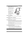
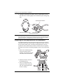
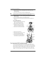
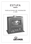
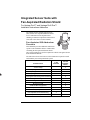
Integrated Sensor Suite with
Fan-Aspirated Radiation Shield
For Vantage Pro2™ and Vantage Pro2 Plus™
Installation Instructions Addendum
The Vantage Pro2™ Integrated Sensor Suite
(ISS) with the Fan-Aspirated Radiation Shield
uses a combination of fan-aspiration and
shielding to minimize temperature measurement
errors due to the effects of solar radiation.
Fan-Aspirated ISS Addendum
Overview
This addendum provides additional information
specific to the installation and use of ISS models
containing the fan-aspirated radiation shield
only, and is intended to be used in conjunction with the “Integrated Sensor
Suite Installation Manual.”
The table below shows the location of the information required to install
and maintain your Fan-Aspirated ISS system.
Section/Procedure
In This
Addendum
Tools for Setup
X
Preparing the Anemometer
X
Preparing the Rain Collector
X
Preparing the Radiation Shield
X
Powering ISS and Testing Communications
Powering and Testing the Fan
In the ISS
Installation
Manual
X
X
X
Choosing a Site for the ISS
X
Mounting the ISS
X
Additional Mounting Options
X
Fan-Aspirated ISS Maintenance
X
Theory of Operation
X
Fan-Aspirated ISS Troubleshooting
X
Fan-Aspirated ISS Specifications
X
1
Fan-Aspirated ISS Addendum Overview
Components
The Fan-Aspirated ISS includes these components:
Rain Collector
Debris Screen
(place inside cone after installation)
Metric
Rain Adapter
Solar Panel
(wireless
ISS only)
Anemometer
Vane
Control
Head
SIM
Housing
Anemometer
Base
Drip
Ring
ISS Base
Anemometer
Arm
Wind Cups
Anemometer Cable
40' (12.2 m)
Aspirated
Radiation
Shield
The hardware shown here is provided for assembly and mounting:
U-Bolts
1/4" Flat Washers
1/4" x 3" Lag Screws
1/4" Lock Washers
1/4" Hex Nuts
Nut Plate
#4 x 1-1/8"
Machine Screw
#4 Tooth Lock Washer
#4-40 Hex Nut
8" Cable Ties
2
.05"
Allen Wrench
Tools for Installation
Additional Components on Vantage Pro Plus
Vantage Pro2 Plus™ includes
an ultraviolet (UV) sensor and
a solar radiation sensor. These
two sensors are mounted next
to the rain collector on your
ISS
UV and Solar
Sensors
Sensor
Mounting Shelf
See the Integrated Sensor Suite
about mounting and maintaining these sensors.
Do not to touch the small
white diffusers on top of the
UV and solar radiation sensors. Oil from the skin reduces
sensor sensitivity.
Tools for Installation
Refer to this section in your ISS Installation Manual on assembling the
anemometer.
Preparing the ISS for Installation
Refer to this section in your ISS Installation Manual on assembling the
anemometer.
Preparing the SIM for Installation
The ISS sensors are connected by cables to the Sensor Interface Module
(SIM), located inside the SIM housing. The SIM contains electronics that
measure and store weather values for transmission to the console via radio.
The SIM housing protects the SIM from the elements and provides easy
access to SIM cable connections.
See the ISS Installation manual on checking the sensor connections to the
SIM and for any additional sensor and wireless installation instructions.
Preparing the Rain Collector
Follow these steps to prepare the rain collector for operation.
1. Remove the rain collector cone from its base by rotating the cone
counter-clockwise until its latches line up with openings which allow
you to lift it off. The cone fits in the base tightly and may require extra
pressure to remove it when new.
Note:
Steady the base between your knees when you rotate the rain collector.
3
Preparing the Fan-aspirated ISS for Installation
2. Carefully cut and remove the plastic cable tie (usually black in color)
that holds the two-sided tipping bucket mechanism in place during shipping.
Tipping bucket mechanism
Twist off the rain collector cone
Cut the plastic cable tie
Preparing the Rain collector
Note:
If installed, the UV and solar radiation sensor cables are routed through the base of the rain collector. Please make sure they do not get moved and make sure they do not interfere with the tipping bucket mechanism or with latching the cone back onto the base. See the ISS Installation
Manual for instructions on inserting the optional metric measurement adapter.
Preparing the Fan-aspirated ISS for Installation
The radiation shield, fan, and solar panel used to power the fan come preassembled with the ISS unit and require no additional assembly. However,
the fan requires initial power from the pre-installed batteries. Tabs are
included to ensure that the batteries that are installed in the fan-aspirated
housing do not power the unit during shipping. To power the fan-aspirated
unit.
1. Remove the cardboard packing
inserts between the passive
shielding, the solar panel, and the
rain collector base and discard.
2. Pull the tabs on the outside of
the shielding slowly.
3. Listen for a slight whir coming from the bottom of the ISS
unit. This sound signifies that
the fan is running.
4
Applying Power and Testing Communications
Applying Power and Testing Communications
Powering the ISS and Testing Communication with the
Console
Refer to Wireless ISS Assembly section in your ISS Installation Manual
for the rest of the procedures required to power and test the ISS.
Locating the ISS and Anemometer
Refer to this section in your ISS Installation Manual.
Mounting the ISS
The fan-aspirated version of the ISS, is mounted and installed just like the
regular version of the ISS. Refer to this section in your ISS Installation
Manual to mount the ISS.
Additional Mounting Options
Refer to this section in your ISS Installation Manual.
Fan-Aspirated ISS Installation Options
Batteries
The Wireless Fan-Aspirated ISS is solar powered and is supplied with two
NiCad C-cell batteries that come pre-installed. The following options for
battery power exist:
• Use two fan batteries for maximum length of overnight aspiration but
with slightly lower average daytime aspiration.
• Use only one fan battery for some overnight aspiration but with slightly
higher average daytime aspiration.
• Remove both batteries for maximum daytime aspiration and no nighttime aspiration.
Fan-Aspirated ISS Maintenance
• Keep the surfaces clean, since the Fan-Aspirated Radiation Shield is
less effective when the surfaces are dirty. Remove dust from the solar
panel and the shield with a damp cloth.
• Remove any debris obstructing air flow through the radiation shield,
e.g., leaves, twigs, webs, and nests.
• Avoid spraying insect killer of any kind into the radiation shield as this
may damage the sensors and the shield.
• Once a year: replace the motor (Part # 7758), batteries, and remove any
debris lodged inside the unit.
Disassemble the Radiation Shield
Disassemble the radiation shield for routine cleaning, maintenance, and to
replace the batteries and motor. To disassemble the shield:
5
Fan-Aspirated ISS Troubleshooting
1. Remove the three screws connecting the rain collector base to the
mounting bracket.
2. Lift the rain collector base off of the mounting bracket.
Note:
For easier re-assembly, mark the holes used by the rain collector base, the holes used by the
radiation shield, and the orientation of the bracket relative to the radiation shield.
3. Remove the three (3) screws connecting the mounting bracket to the
radiation shield.
4. Lift the mounting bracket off of the radiation shield.
5. Remove all debris from inside the shield and replace the batteries if
necessary.
Annual Maintenance
1. Retrieve your Fan-Aspirated ISS and
place on a stable work surface.
2. Disassemble the radiation shield.
3. Unplug the old motor and remove
from it from the Radiation Shield.
4. Install the new motor/fan assembly.
Fan Unit
Motor Connector
Fan Deflecto
Temp/Hum
Sensor Cable
Channel
Junction Bo
Fan Pla
5.
6.
7.
8.
Remove the fan batteries.
Install new batteries (NiCad C-cells).
Assemble the Radiation Shield.
Re-mount the Fan-Aspirated Radiation Shield in its previous location.
#4 Screws
Battery Cover
Air
Flow
1.2 Volt Nicad
Battery
O-Ring
Battery
Compartment
Fan-Aspirated ISS Troubleshooting
If you are experiencing problems with your Fan-Aspirated ISS, first be
sure to check all cable connections. If you are unable to solve the problem,
please call Davis Technical Support. We’ll be glad to help. Most questions
can be answered while you’re on the phone. You can also e-mail us for
support, or visit our website. Sorry, we are unable to accept collect calls.
6
Fan-Aspirated ISS Troubleshooting
Note:
Please do not return items to the factory for repair without prior authorization.
Contacting Davis Instruments
(510) 732-7814 for Technical Support, Monday – Friday, 7:00 a.m. – 5:30
p.m. Pacific Time.
[email protected] E-mail to Technical Support.
(510) 670-0589 Fax to Customer Service or Tech Support.
www.davisnet.com Copies of User Manuals are available on the “Support”
page. Watch for FAQs and other updates. Subscribe to the e-newsletter.
Theory of Operation
The diagram below shows how the Fan-Aspirated Radiation Shield draws
outside air up through the sensor chamber and between the three walls surrounding the sensor chamber.
MOTOR
FAN
SENSOR
CHAMBER
Cross-section of Fan-Aspirated Radiation Shield
Fan-Aspirated ISS Specifications
Aspiration Rate . . . . . . . . . . . . . . . . . . 190 ft./min. (.96 m/s) (solarpowered, full sun), 80 feet/min. (0.4
m/s) (battery only)
Radiation-Induced Temperature Error. . 0.5°F (0.3°C)
[At solar noon, insolation = 1040 W/
m2]
7
(Reference: RM Young model
43408)
Operating Temperature . . . . . . . . . . . . –40° to +140° F (–40° to +60° C)
Non-operating Temperature . . . . . . . . . –50° to +158° F (–45° to +70° C)
ISS Primary Power Input
Wireless ISS . . . . . . . . . . . . . . . . . . . . solar panel
ISS secondary power . . . . . . . . . . . . . . CR-123A 3-volt lithium battery (8
months without sunlight to greater
than two years depending on solar
charging)
Fan Primary Power Input
Wireless ISS . . . . . . . . . . . . . . . . . . . . . solar panel
Fan secondary power . . . . . . . . . . . . . . 1 or 2 - 1.2 Volt NiCad C-cells
FCC Part 15 Class B Registration Warning
This equipment has been tested and found to comply with the limits for a Class B digital device, pursuant to Part 15 of the FCC Rules.
These limits are designed to provide reasonable protection against harmful interference in a residential installation. This equipment
generates, uses, and can radiate radio frequency energy and, if not installed and used in accordance with the instructions, may
cause harmful interference to radio communications.
However, there is no guarantee that interference will not occur in a particular installation. If this equipment does cause harmful interference to radio or television reception, which can be determined by turning the equipment on and off, the user is encouraged to try to
correct the interference by one or more of the following measures:
•
Reorient or relocate the receiving antenna.
•
Increase the separation between the equipment and receiver.
•
Connect the equipment into an outlet on a circuit different from that to which the receiver is connected.
•
Consult the dealer or an experienced radio/TV technician for help.
Changes or modification not expressly approved in writing by Davis Instruments may void the warranty and void the user's authority
to operate this equipment.
IC: 378810-6328
EC EMC Compliance
This product complies with the essential protection requirements of the EC EMC Directive 89/336/EC.
Addendum, Fan-Aspirated ISS Installation
Rev A Manual (November 10, 2004)
Document Part Number: 7395.252
Product Number:6153, 6163
Vantage Pro® and Vantage Pro2™ are trademarks of Davis Instruments Corp., Hayward, CA.
© Davis Instruments Corp. 2004. All rights reserved.
Information in this document subject to change without notice.