1
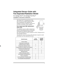
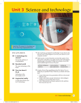
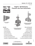
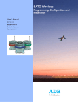
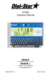
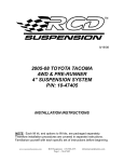
CLIF MOCK™
LGS-2000
Sampling System
User Manual
Manual No. 9A-70165003, Rev. 01
Important Safety Information
Symbols and Terms Used in this Manual
!
WARNING: This symbol identifies information about practices or circumstances that can lead to personal injury or death, property damage, or economic loss.
CAUTION: Indicates actions or procedures which if not performed correctly may lead to personal
injury or incorrect function of the instrument or connected equipment.
Important: Indicates actions or procedures which may affect instrument operation or may lead to an
instrument response which is not planned.
Technical Support Contact Information
Cameron
Measurement Systems Division
14450 John F. Kennedy Blvd.
Houston, TX 77032
Phone: 1-800-654-3760; 281-582-9500
Fax: 281-582-9599
Clif Mock is a trademark of Cameron International Corporation (“Cameron”).
© 2011 Cameron International Corporation (“Cameron”). All information contained in this publication is confidential and proprietary property of Cameron. Any reproduction or use of these instructions, drawings, or
photographs without the express written permission of an officer of Cameron is forbidden.
All Rights Reserved.
Printed in the United States of America.
Manual No. 9A-70165003, Rev. 01
June 2011
LGS-2000 Sampling System
Table of Contents
Contents
Section 1—LGS-2000 System Overview......................................................................................................... 5
LGS 2000 System Components.......................................................................................................................... 6
LGS-1 Pump ................................................................................................................................................ 6
Air Pressure Regulator . ............................................................................................................................... 7
Pressure Gauge............................................................................................................................................ 7
Other Required Customer-Supplied Equipment.................................................................................................. 7
Sample Probe ............................................................................................................................................. 7
Sample Receiver........................................................................................................................................... 8
External Air Supply........................................................................................................................................ 8
Safety Barrier................................................................................................................................................ 8
Product Identification........................................................................................................................................... 8
Table 1.1—LGS-2000 Sampler Specifications.............................................................................................. 9
Section 2—System Installation.......................................................................................................................11
General Information............................................................................................................................................11
Hazardous Area Precautions..............................................................................................................................11
External Power.............................................................................................................................................11
Communications..........................................................................................................................................11
Installation Procedure.........................................................................................................................................11
Section 3—LGS-2000 Sampling System Parts............................................................................................. 17
Table 3.1—True Cut 2000 Controller.......................................................................................................... 17
Table 3.2—LGS-1 Pump............................................................................................................................. 17
Table 3.3—Regulators and Gauges............................................................................................................ 17
Table 3.4—Accessories.............................................................................................................................. 18
iii
Table of Contents
iv
LGS-2000 Sampling System
LGS-2000 Sampling System
Section 1
Section 1—LGS-2000 System Overview
The Clif Mock LGS-2000 Sampling System pairs a microcontroller-based electronic sample controller with
an integral liquid/gas sample pump for sampling liquid or gas flow streams. The sample pump connects
directly or remotely to a sample probe and to a sampler receiver used to collect samples for analysis. See the
Cameron website or contact your local Cameron sales representative for information on Cameron probes and
receivers, sold separately.
The LGS-2000 system is designed to operate with system pressures ranging between 30 psi to 1200 psi with
the standard solenoid (30 psi to 1500 with the premium solenoid) and system temperatures ranging from –15°
to 375°F.
The standard system is powered by an internal 7.2-volt lithium battery pack for long-lasting performance. At a
sampling rate of one sample every 10 minutes, the battery is shown to last an average of 18 months. In solarpowered applications, a rechargeable lead acid battery is substituted. An external DC power supply can also
be used to power the system, in which case the lithium battery provides backup protection.
The system supports two flow volume inputs. It can detect a signal from the magnetic pickup of a turbine
flowmeter in the range of 20 mV to 200 mV, peak to peak, and it can sense a positive displacement meter
contact closure input.
While external communications are not required for operating the LGS-2000 system, external Modbus
communicating devices or Modbus SCADA systems can be connected to the controller for collecting realtime data or for configuring the controller remotely.
The system is CSA certified for use in Class I, Division 1, Groups A, B, C, and D hazardous areas when
installed in accordance with Cameron instructions. If an external 12V power supply is to be used in a
hazardous area, power must be routed through a CSA-certified safety barrier to retain CSA certification.
This document describes the installation and typical configuration of the LGS-2000 system. For additional
information about the installation, operation and maintenace of individual components, see the following
component manuals provided with the LGS-2000 system, and available for download from the Cameron
Measurement Systems website:
•
True Cut 2000 Sampler Controller User Manual, Part No. 9A-70165002
•
LGS-1 Sample Pump User Manual, Part No. 9A-99104500147
5
Section 1
LGS-2000 Sampling System
Battery
Circuit board
Solenoid
Vent
Bracket
Sample size
adjustment knob
Regulator
Gauge
LGS-1 Pump
Sample discharge outlet
(plumb to receiver)
Figure 1.1—LGS-2000 components
LGS 2000 System Components
Sampler Controller
The TrueCut 2000 Sampler Controller can be configured as a timer or a pulse counter for sampling product
proportional to time or proportional to volume. This allows external pacing devices such as positive
displacement meters, turbines meters, or dry contact closures from computers to control the sampling
frequency while the controller displays the total volume and flow rate. Ideally, the controller should be
configured prior to installing the system in the field.
LGS-1 Pump
The controller is connected to the sample pump by a bracket and collar assembly. When the pump is correctly
positioned inside the collar, a set screw in the side of the collar (Figure 1.2) is used to secure the pump to the
bracket.
6
LGS-2000 Sampling System
Section 1
Figure 1.2—Sample pump and bracket assembly
Air Pressure Regulator
The regulator supplied with the LGS 2000 Sampling System ensures that incoming air pressure is reduced
to 120 psi before it reaches the solenoid. Cameron’s standard regulator input is rated at 3000 psi maximum.
Additionally, a premium regulator (3600 psi maximum) is available with stainless steel construction, and an
economy model (300 psi maximum) is available for use with external compressed air.
The standard or premium regulator is plumbed to either a fitting on the pump (when pipeline pressure is
actuating the pump), or to an external air supply (recommended for liquid applications and some low-pressure
gas applications). The economy regulator can be used only with an external air supply.
Pressure Gauge
A 2-in. pressure gauge is mounted at the top of the regulator, and provides a readout of actuation air pressure.
See the LGS-1 Sample Pump User Manual for a chart that can be used to determine the appropriate actuation
air pressure for a specific application. To set the pressure, adjust the regulator knob on the back of the sampler
bracket.
Other Required Customer-Supplied Equipment
Sample Probe
A sample probe delivers the sample fluid to the supply inlet of the purge valve manifold connected to the
bottom of the pump. The probe should be made of non corrosive material. 316 stainless steel tubing is
recommended.
7
Section 1
LGS-2000 Sampling System
Sample Receiver
A vented receiver or pressure-balanced cylinder should be connected to the discharge outlet of the pump to
collect the samples. The size of the receiver is typically entered into the controller when configuring sample
frequency.
If a pressurized receiver is used, an outlet check valve should be installed between the sample discharge outlet
and the receiver to prevent the process fluid from flowing back back to the pump. The valve is an accessory
supplied by Cameron (Part No. 9A-50142303543).
External Air Supply
Pipeline gas is frequently used to actuate the pump in gas sampling applications. However, in liquid
applications and some low-pressure gas applications, an external air supply is required. To determine whether
an external air supply is required for a gas application, the user must determine the pipeline pressure of the
fluid to be sampled. If pipeline pressure is below 15 psi, an external air supply is required to actuate the pump.
See the LGS-1 Sample Pump User Manual for details.
Safety Barrier
If an external 12V power supply is to be used, and the LGS-2000 is installed in a hazardous area, power must
be routed through a CSA-certified safety barrier. See the True Cut 2000 Sampler Controller User Manual for
minimum safety barrier requirements.
Product Identification
A serial tag mounted to the outside of the controller enclosure identifies the product by its part number and
serial number (Figure 1.3). The maximum working pressure of the LGS-2000 is stamped on the tag, along
with the working pressure of the controller (Solenoid Max WP). Each tag is also marked to show which
battery pack is installed and the temperature range for which it is rated.
Figure 1.3—Serial tag
8
LGS-2000 Sampling System
Section 1
Table 1.1—LGS-2000 Sampler Specifications
Sampler Controller
True Cut 2000 Sampler Controller
Supports time-based and volume-based sampling of gases and liquids
Accepts inputs from turbine flowmeters and pulse-generating devices
See the True Cut 2000 Sampler Controller User Manual, Part No.
9A-70165002, for enclosure, solenoid, power supply, keypad security,
and input/output specifications.
Power Supply
7.2V lithium battery pack, 6V rechargeable lead acid battery and solar
panel, or 9-15V external power supply
See the True Cut 2000 Sampler Controller User Manual, Part No. 9A70165002, for details.
Operating Environment
-40°F to 140°F (-40°C to 60°C) or -40°F to 104°F (-40°C to 40°C),
battery dependent
0 to 90% non-condensing relative humidity
LCD contrast is reduced below -22°F (-30°C)
Pump
LGS-1 Sample Pump
Stainless steel construction
Maximum working pressure: 1500 psi
See the LGS-1 Sample Pump User Manual, Part No.
9A-99104500147, for details.
Regulator
Standard: 3000 PSI in, 200 PSI max out (brass)
Premium: 3600 PSI in, 200 PSI max out (stainless steel)
Economy: 300 PSI in, 200 PSI max out (zinc), external air is required
Maximum Air Pressure to Solenoid
100 psi (standard solenoid) or 120 psi (premium stainless steel
solenoid)
See the True Cut 2000 Sampler Controller User Manual, Part No.
9A-70165002, for details.
Communications
2 RS-485 communication ports (RTU Modbus®)
See the True Cut 2000 Sampler Controller User Manual, Part No.
9A-70165002, for wiring details.
Mounting Options
Direct mount to sample probe
Remote mount to 2-in. vertical pipe with top-of-pipe mount or U-bolts
Safety Approval
Intrinsically Safe - Class I, Division 1, Groups C and D for use in the
US and Canada
9
Section 1
10
LGS-2000 Sampling System
LGS-2000 Sampling System
Section 2
Section 2—System Installation
General Information
The LGS-2000 Sampling System can be mounted using any of three basic methods:
•
Direct Mount (Recommended)—The sampler may be mounted directly on the sample probe. This eliminates the need for tubing and provides the shortest path for the sample fluid. This method is preferred
when the piping configuration allows. If pipeline vibration is a concern, additional support may be added
for the enclosure.
•
Remote Mount (Bulkhead)—The sampler may be bulkhead-mounted to a flat surface using holes provided in the mounting bracket supplied with the LGS-2000 system. A stainless steel tube is used to convey
the sample fluid from the sample probe to the inlet of the purge valve manifold.
•
Remote Mount (Pipe Mount)—The sampler may be mounted to a 2-in. vertical pipe using a pair of Ubolts or a top-of-pipe bracket, both sold separately. A stainless steel tube is used to convey the sample
fluid from the sample probe to the inlet of the purge valve manifold.
Step-by-step instructions for installing the system are provided below. See Figures 2.4 and 2.5, pages 14 and
15, for typical arrangement of direct-mount and remote-mount installations.
Hazardous Area Precautions
External Power
When powering the True Cut 2000 in a hazardous area with 9-15 VDC power supply, the cable must be routed
through an I.S.-rated safety barrier in the safe area. The barrier must be rated for 15V maximum and 40 ohms
minimum. The power supply and cable must be capable of supplying 8 to 15 VDC @ 375 mA through the
intrinsic safety barrier. The external power supply must be an approved SELV source, insulated from the AC
main by double/ reinforced insulation per CSA C22.2 No. 61010-1-04/ UL 61010-1 – 2nd Edition.
Important: A switch or circuit breaker must be included in the safe area external power supply installation within easy reach of the operator. The switch or circuit breaker must be marked
as the “disconnect” for the external DC power supply.
Communications
When the True Cut 2000 controller is connected to an external communications device via an RS-485 port,
power must be routed through an I.S.-rated safety barrier.
Installation Procedure
The following procedure is a guide to a typical installation. Tubing arrangements will vary, depending on
the product sampled (gas or liquid). Typical connections are shown in Figures 2.4 and 2.5, pages 14 and 15.
For more information on remote mount or fast-loop tubing configurations, see the LGS-1 Sample Pump User
Manual.
1. Mount the sample probe vertically in a horizontal pipe run as per API Chapter 8, Section 2 and be located
as per API Chapter 8, Section 2, Appendix A. The end of the sample probe should be cut at a 45º angle to
the pipeline and should penetrate into the center one half of the pipeline.
11
Section 2
LGS-2000 Sampling System
2. Connect the pump either directly or indirectly to the sample probe, as described in the LGS-1 Sample
Pump User Manual supplied with the LGS-2000 system.
3. Connect the pump discharge outlet to the sample receiver using 1/4 in. stainless steel tubing.
Important
If a pressurized receiver is used, install an outlet check valve between the sample discharge outlet and the receiver to prevent the process fluid from flowing back back to the
pump. The valve is an accessory supplied by Cameron (Part No. 9A-50142303543).
4. Make sure the “inlet” and “outlet” connections at the bottom of the controller enclosure are secure;
tighten if required. The “inlet” connection supplies air pressure from the regulator to the solenoid inside
the enclosure. The “outlet:” connection supplies air pressure from the solenoid to actuate the pump.
Incoming air
to solenoid
Outgoing air
to pump
Figure 2.1—Controller inlet and outlet connections
5. If using an external air supply, connect the air supply discharge outlet to the regulator using stainless tubing. If process gas will be used to actuate the pump, the air supply tubing will be connected to the pump at
the factory as shown in Figure 2.2.
6. Adjust the regulator adjustment knob until the pressure gauge displays the appropriate pump actuation
pressure for the application.
Regulator
adjustment knob
Pressure
gauge
Figure 2.2—Regulator adjustment control
12
LGS-2000 Sampling System
Section 2
7. If a fast loop connection is required, connect the reinjection line fitting in the side of the purge valve
manifold to the low-pressure side of the orifice fitting in the pipeline as shown in Figure 2.5, page 15. See
Figure 2.3 for the location of the fast-loop reinjection line fitting. Also see the LGS-1 Sample Pump User
Manual, Part No. 9A-99104500147, for additional details.
8. Cover the vent hole in the side of the pump with 1/16-17 NPT screen, if necessary, to prevent buildup of
debris in the hole.
Vent hole
(cover with
1/16-17 NPT screen
to prevent buildup
of debris)
Actuation
pressure port, 1/8 in. NPT female
Sample outlet
(connects to
sample receptacle),
1/4 in. NPT female
Purge valve
Fast-loop reinjection line
1/4 in. NPT female
(optional)
Sample inlet, 1/2 in. NPT male
Air supply to regulator, 1/4 in. NPT female
(180 degrees from purge valve)
Figure 2.3—Pump tubing connections; note the orientation of the images above (the photo on the right is
rotated 90 degrees clockwise from the position shown in the left photo)
9. Connect field wiring (flowmeter input, solenoid, and if desired, communications) to the controller following the instructions provided in the True Cut 2000 Sampler Controller User Manual.
Important: Before attempting to operate the LGS-2000 system, make sure the solenoid valve assembly cable is securely connected to TB2 on the controller circuit board. When power
is supplied to the device, an audible clicking sound is generated when the solenoid is
operating properly.
10. Connect power (battery or external power) and observe the display boot-up sequence.
11. Set the sample size by adjusting the pump, and configure the controller. Instructions are provided in the
True Cut 2000 Sampler Controller User Manual, Part No. 9A-70165002, and on laminated quick reference cards supplied inside the controller enclosure.
13
Section 2
LGS-2000 Sampling System
Controller
Solenoid
Air supply from solenoid to pump
Air supply
from regulator
to solenoid
Regulator
Pressure gauge
Output pressure gauge
(sold separately)
Pump
Fast-loop connection
(optional)
Receiver
(sold separately)
Pipeline
Sample probe
(sold separately)
Figure 2.4—Direct-mount installation, shown with optional fast-loop connections
14
LGS-2000 Sampling System
Section 2
Controller
Solenoid
Air supply from solenoid to pump
Air supply
from regulator
to solenoid
Regulator
Pressure gauge
Sampler outlet assembly
(sold separately)
Pump
Connects to fast loop
port on back of pump
Sampler
isolation
assembly
(sold separately)
Receiver
(sold
separately)
Probe and valve assembly
(sold separately)
High Pressure
Low Pressure
Figure 2.5—Remote-mount installation, shown with optional fast-loop connections
15
Section 2
16
LGS-2000 Sampling System
LGS-2000 Sampling System
Section 3
Section 3—LGS-2000 Sampling System Parts
!
WARNING: EXPLOSION HAZARD—Substitution of components may impair suitability for
Class I, Division 1. Use of spare parts other than those identified by Cameron International
Corporation voids hazardous area certification. Cameron bears no legal responsibility for the
performance of a product that has been serviced or repaired with parts that are not authorized
by Cameron.
Table 3.1—True Cut 2000 Controller
Part Number
Description
2295850-01
Circuit Board Assembly
9A-70099001
Battery Assembly, Lithium Pack, 7.2 VDC (2 D Cell)
2296472-01
Battery Assembly, Lead Acid, 6 VDC
2296473-01
Assembly, Solar Panel with Connector (for use with lead acid battery pack
Part No. 2296472-01)
2296735-01
Standard Solenoid with Diode Assembly, 100 psi (plastic)
2296736-01
Premium Solenoid with Diode Assembly, 120 psi (stainless steel)
9A-50132600271
Direct Mount Solar Installation Kit (includes solar panel, mounting hardware,
lead acid battery pack and cable/connector)
2296685-01
Remote Mount Solar Installation Kit (includes solar panel, mounting
hardware, lead acid battery pack and cable/connector)
Table 3.2—LGS-1 Pump
Part Number
Description
9A-50132160150
LGS-1 Sample Pump Assembly
9A-50142150715
Overhaul Kit (contains O-rings and springs for full overhaul of the LGS-1
pump)
9A-50142150708
Seal Kit (contains O-rings for the LGS-1 pump and purge valve manifold)
9A-50142200643
Filter, LGS-1, 40-micron
Table 3.3—Regulators and Gauges
Part Number
Description
2296099-01
Standard Regulator, 3000 PSI input, 200 psi max output (brass)
9A-50142200605
Premium Regulator, 3600 PSI input, 200 psi max output (stainless steel)
9A-50142208070
Economy Regulator, 300 PSI input, 200 psi max output (zinc), external air
required
2296179-01
Gauge, 0-160 psi
2296180-01
Gauge, 0-300 psi
17
Section 3
LGS-2000 Sampling System
Table 3.4—Accessories
18
Part Number
Description
9A-66046405010
Hardware, Remote Mount, Top of Pole
9A-100023269
Hardware, Remote Mount, U-Bolt, Set of Two
9A-50132307870
True Cut Probe and Valve Assembly
9A-50142303543
Outlet Check Valve, 1 psi (required for installations with pressurized
receivers)
WARRANTY - LIMITATION OF LIABILITY: Seller warrants only title to the products, software,
supplies and materials and that, except as to software, the same are free from defects in workmanship and materials for a period of one (1) year from the date of delivery. Seller does not
warranty that software is free from error or that software will run in an uninterrupted fashion.
Seller provides all software “as is”. THERE ARE NO WARRANTIES, EXPRESS OR IMPLIED,
OF MERCHANTABILITY, FITNESS OR OTHERWISE WHICH EXTEND BEYOND THOSE
STATED IN THE IMMEDIATELY PRECEDING SENTENCE. Seller’s liability and Buyer’s exclusive remedy in any case of action (whether in contract, tort, breach of warranty or otherwise)
arising out of the sale or use of any products, software, supplies, or materials is expressly limited
to the replacement of such products, software, supplies, or materials on their return to Seller
or, at Seller’s option, to the allowance to the customer of credit for the cost of such items. In no
event shall Seller be liable for special, incidental, indirect, punitive or consequential damages.
Seller does not warrant in any way products, software, supplies and materials not manufactured
by Seller, and such will be sold only with the warranties that are given by the manufacturer
thereof. Seller will pass only through to its purchaser of such items the warranty granted to it
by the manufacturer.
+603.5569.0501
ms-kl @ c-a-m.com
RUSSIA