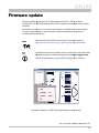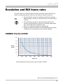
1
AVT Prosilica GC
Technical Manual
AVT GigE Vision Cameras
V2.0.1
70-0064
7 September 2011
Allied Vision Technologies Canada Inc.
101-3750 North Fraser Way
V5J 5E9, Burnaby, BC / Canada
Legal notice
For customers in the U.S.A.
This equipment has been tested and found to comply with the limits for a Class A digital device, pursuant
to Part 15 of the FCC Rules. These limits are designed to provide reasonable protection against harmful
interference when the equipment is operated in a residential environment. This equipment generates,
uses, and can radiate radio frequency energy and, if not installed and used in accordance with the
instruction manual, may cause harmful interference to radio communications. However there is no
guarantee that interferences will not occur in a particular installation. If the equipment does cause
harmful interference to radio or television reception, the user is encouraged to try to correct the
interference by one or more of the following measures:
• Reorient or relocate the receiving antenna.
• Increase the distance between the equipment and the receiver.
• Use a different line outlet for the receiver.
• Consult a radio or TV technician for help.
You are cautioned that any changes or modifications not expressly approved in this manual could void
your authority to operate this equipment. The shielded interface cable recommended in this manual must
be used with this equipment in order to comply with the limits for a computing device pursuant to Subpart
A of Part 15 of FCC Rules.
For customers in Canada
This apparatus complies with the Class A limits for radio noise emissions set out in the Radio Interference
Regulations.
Pour utilisateurs au Canada
Cet appareil est conforme aux normes classe A pour bruits radioélectriques, spécifiées dans le Règlement
sur le brouillage radioélectrique.
Life support applications
These products are not designed for use in life support appliances, devices, or systems where malfunction
of these products can reasonably be expected to result in personal injury. Allied Vision Technologies
customers using or selling these products for use in such applications do so at their own risk and agree to
fully indemnify Allied for any damages resulting from such improper use or sale.
Trademarks
Unless stated otherwise, all trademarks appearing in this document of Allied Vision Technologies are
brands protected by law.
Warranty
The information provided by Allied Vision Technologies is supplied without any guarantees or warranty
whatsoever, be it specific or implicit. Also excluded are all implicit warranties concerning the
negotiability, the suitability for specific applications or the non-breaking of laws and patents. Even if we
assume that the information supplied to us is accurate, errors and inaccuracy may still occur.
Copyright
All texts, pictures and graphics are protected by copyright and other laws protecting intellectual property.
It is not permitted to copy or modify them for trade use or transfer, nor may they be used on web sites.
Allied Vision Technologies Canada Inc. 7/2011
All rights reserved.
Managing Director: Mr. Frank Grube
TaxID: 889528709
Headquarters:
101-3750 North Fraser Way
V5J 5E9, Burnaby, BC / Canada
AVT Prosilica GC Technical Manual V2.0.1
2
Contents
Contacting Allied Vision Technologies ............................................................. 6
Introduction ................................................................................................................. 7
Document history ..................................................................................................... 7
Symbols used in this manual ....................................................................................... 8
Warranty ................................................................................................................ 8
Precautions ............................................................................................................. 9
Cleaning the sensor ................................................................................................ 10
Conformity ................................................................................................................. 11
Specifications ........................................................................................................... 12
Prosilica GC650/650C .............................................................................................. 12
Prosilica GC655/655C .............................................................................................. 14
Prosilica GC660/660C .............................................................................................. 16
Prosilica GC750/750C .............................................................................................. 18
Prosilica GC780/780C .............................................................................................. 20
Prosilica GC1020/1020C........................................................................................... 22
Prosilica GC1280 .................................................................................................... 24
Prosilica GC1290/1290C........................................................................................... 26
Prosilica GC1350/1350C........................................................................................... 28
Prosilica GC1380/1380C........................................................................................... 30
Prosilica GC1380H/1380CH ...................................................................................... 32
Prosilica GC1600/1600C........................................................................................... 34
Prosilica GC1600H/1600CH ...................................................................................... 36
Prosilica GC2450/2450C........................................................................................... 38
Camera attribute highlights ...................................................................................... 40
IR cut filter: spectral transmission .................................................................. 41
Camera dimensions ............................................................................................... 42
Prosilica GC CMOS models ......................................................................................... 42
Prosilica GC CCD models ........................................................................................... 43
Tripod adapter ....................................................................................................... 44
AVT Prosilica GC Technical Manual V2.0.1
3
Adjustment of lens mount ........................................................................................ 45
Camera interfaces .................................................................................................. 46
Camera I/O connector pin assignment......................................................................... 47
Gigabit Ethernet Port .............................................................................................. 50
Camera I/O internal circuit diagram............................................................................ 51
Camera I/O opto-isolated user circuit example.............................................................. 53
Camera I/O non-isolated user circuit example............................................................... 54
Video iris output description ..................................................................................... 55
Notes on triggering ................................................................................................ 56
Timing diagram ...................................................................................................... 56
Signal definitions ................................................................................................... 57
Trigger rules.......................................................................................................... 58
Firmware update ..................................................................................................... 59
Resolution and ROI frame rates ........................................................................ 60
CAMERA: Prosilica GC650.......................................................................................... 60
CAMERA: Prosilica GC655.......................................................................................... 61
CAMERA: Prosilica GC660.......................................................................................... 61
CAMERA: Prosilica GC750.......................................................................................... 62
CAMERA: Prosilica GC780.......................................................................................... 62
CAMERA: Prosilica GC1020 ........................................................................................ 63
CAMERA: Prosilica GC1280 ........................................................................................ 63
CAMERA: Prosilica GC1290 ........................................................................................ 64
CAMERA: Prosilica GC1350 ........................................................................................ 64
CAMERA: Prosilica GC1380 ........................................................................................ 65
CAMERA: Prosilica GC1380H ...................................................................................... 65
CAMERA: Prosilica GC1600 ........................................................................................ 66
CAMERA: Prosilica GC1600H ...................................................................................... 66
CAMERA: Prosilica GC2450 ........................................................................................ 67
Prosilica GC frame rate performance comparison ........................................................... 68
Sensor position of Prosilica GC cameras ...................................................... 69
AVT Prosilica GC Technical Manual V2.0.1
4
Additional references ............................................................................................ 70
Prosilica GC webpage............................................................................................... 70
Prosilica GE Documentation ...................................................................................... 70
AVT GigE PvAPI SDK ................................................................................................. 70
AVT Knowledge Base ............................................................................................... 70
AVT Case Studies .................................................................................................... 70
Prosilica GC Firmware .............................................................................................. 70
AVT Prosilica GC Technical Manual V2.0.1
5
Contacting Allied Vision Technologies
•
Technical information:
http://www.alliedvisiontec.com
•
Support:
[email protected]
Allied Vision Technologies GmbH
Taschenweg 2a
07646 Stadtroda, Germany
Tel.: +49.36428.677-0
Fax.: +49.36428.677-28
e-mail: [email protected]
Allied Vision Technologies Inc.
38 Washington Street
Newburyport, MA 01950, USA
Toll Free number +1-877-USA-1394
Tel.: +1 978-225-2030
Fax: +1 978-225-2029
e-mail: [email protected]
Allied Vision Technologies Canada Inc.
101-3750 North Fraser Way
Burnaby, BC, V5J 5E9, Canada
Tel: +1 604-875-8855
Fax: +1 604-875-8856
e-mail: [email protected]
Allied Vision Technologies Asia Pte. Ltd.
82 Playfair Road
#07-02 D'Lithium
Singapore 368001
Tel. +65 6634-9027
Fax:+65 6634-9029
e-mail: [email protected]
AVT Prosilica GC Technical Manual V2.0.1
6
Introduction
This AVT Prosilica GC Technical Manual describes in depth the technical specifications
of this camera family including dimensions, feature overview, I/O definition, trigger
timing waveforms, frame rate performance, etc.
For information on software installation read the AVT GigE Installation Manual.
For detailed information on camera features and controls refer to the AVT Prosilica GigE
Camera and Driver Attributes document.
AVT Prosilica GC literature:
http://www.alliedvisiontec.com/us/support/downloads/productliterature/prosilica-gc.html
Please read through this manual carefully.
Document history
Version
Date
Remarks
V2.0.1
7.10.11
Added note to Figure 34.
V2.0.0
22.07.11
New Manual – RELEASE Status
Table 1: Document History
AVT Prosilica GC Technical Manual V2.0.1
7
Symbols used in this manual
This symbol highlights important information
This symbol highlights important instructions. You have to follow these
instructions to avoid malfunctions.
This symbol highlights URLs for further information. The URL itself is
shown in blue.
Example:
http://www.alliedvisiontec.com
Warranty
Allied Vision Technologies Canada provides a 2 year warranty which
covers the replacement and repair of all AVT parts which are found to be
defective in the normal use of this product. AVT will not warranty parts
which have been damaged through the obvious misuse of this product.
AVT Prosilica GC Technical Manual V2.0.1
8
Precautions
DO NOT OPEN THE CAMERA. WARRANTY IS VOID IF CAMERA IS
OPENED.
This camera contains sensitive components which can be damaged if
handled incorrectly.
KEEP SHIPPING MATERIAL.
Poor packaging of this product can cause damage during shipping.
VERIFY ALL EXTERNAL CONNECTIONS.
Verify all external connections in terms of voltage levels, power
requirements, voltage polarity, and signal integrity prior to powering
this device.
CLEANING.
This product can be damaged by some volatile cleaning agents. Avoid
cleaning the image sensor unless absolutely necessary. Please see
instructions on sensor cleaning in this document.
DO NOT EXCEED ENVIRONMENTAL SPECIFICATIONS.
See environmental specifications limits in the Specifications section of
this document. Special care is required to maintain a reasonable
operating temperature. If the camera is to be operated in a warm
environment, it is suggested that the camera be mounted on a heat sink
such as a metal bracket and that there is sufficient air flow.
AVT Prosilica GC Technical Manual V2.0.1
9
Cleaning the sensor
DO NOT CONTACT CLEAN SENSOR UNLESS
ABSOLUTELY NECESSARY
Identifying Debris
Debris on the image sensor or optical components will appear as a darkened area or smudge on the image
that does not move as the camera is moved. Do not confuse this with a pixel defect which will appear as a
distinct point.
Locating Debris
Before attempting to clean the image sensor, it is important to first determine that the problem is due to
debris on the sensor window. To do this you should be viewing a uniform image, such as a piece of paper,
with the camera. Debris will appear as a dark spot or dark region that does not move as the camera is
moved. To determine that the debris is not on the camera lens, rotate the lens independent of the
camera. If the spot moves as the lens moves, then the object is on the lens -not on the image sensor- and
therefore cleaning is not required. If the camera has an IR filter, then rotate the IR filter. If the object
moves then the particle is on the IR filter not the sensor. If this is the case remove the IR filter carefully
using a small flat head screw driver. Clean both sides of the IR filter using the same techniques as
explained below for the sensor window.
DO NOT TOUCH ANY OPTICS WITH FINGERS. OIL FROM
FINGERS CAN DAMAGE FRAGILE OPTICAL COATINGS.
Cleaning with Air
If it is determined that debris is on the sensor window, then remove the camera lens, and blow the sensor
window directly with clean compressed air. If canned air is used, do not shake or tilt the can prior to
blowing the sensor. View a live image with the camera after blowing. If the debris is still there, repeat this
process. Repeat the process a number of times with increased intensity until it is determined that the
particulate cannot be dislodged. If this is the case then proceed to the contact cleaning technique.
Contact Cleaning
Only use this method as a last resort. Use 99% laboratory quality isopropyl alcohol and clean cotton
swabs. Dampen the swab in the alcohol and gently wipe the sensor in a single stroke. Do not reuse the
same swab. Do not wipe the sensor if the sensor and swab are both dry. You must wipe the sensor quickly
after immersion in the alcohol, or glue from the swab will contaminate the sensor window. Repeat this
process until the debris is gone. If this process fails to remove the debris, then contact AVT.
AVT Prosilica GC Technical Manual V2.0.1
10
Conformity
Allied Vision Technologies declares under its sole responsibility that all standard
cameras of the AVT Prosilica GC family to which this declaration relates are in
conformity with the following standard(s) or other normative document(s):
•
CE, following the provisions of 2004/108/EG directive
•
FCC Part 15 Class A
•
RoHS (2002/95/EC)
We declare, under our sole responsibility, that the previously described AVT Prosilica GC
cameras conform to the directives of the CE.
Note: This equipment has been tested and found to comply with the limits for a Class A
digital device, pursuant to part 15 of the FCC Rules. These limits are designed to provide
reasonable protection against harmful interference in a residential environment. This
equipment generates, uses, and can radiate radio frequency energy and, if not installed
and used in accordance with the instructions, may cause harmful interference to radio
communications. Operation of this equipment in a residential area is likely to cause
harmful interference in which case the user will be required to correct the interference
at his own expense. You are cautioned that any changes or modifications not expressly
approved in this manual could void your authority to operate this equipment.
AVT Prosilica GC Technical Manual V2.0.1
11
Specifications
Prosilica GC
650/650C
Resolution
659 x 493
Sensor
Type
Sony ICX424AL, ICX424AQ for color
CCD Progressive
Sensor size
Cell size
Type 1/3
7.4 μm
Lens mount
Max frame rate at full resolution
C/CS
90 fps
A/D
On-board FIFO
12 bit
16 MB
Bit depth
Mono formats
Color formats
8/12
GC650: Mono8, Mono12, Mono16
GC650C: Mono8
Bayer8, Bayer16, YUV411, YUV422, YUV444, RGB24, BGR24, RGBA24, BGRA24
Exposure control
Gain control
10 µs to 60 seconds; 1 µs increments
0 to 19 dB
Horizontal binning
Vertical binning
1 to 8 pixels
1 to full resolution
TTL I/Os
Opto-coupled I/Os
1 input, 1 output
1 input, 1 output
RS-232
Power requirements
1
5-16 VDC Cameras SN: 02-XXXXX-0XXXX
5-25 VDC Cameras SN: 02-XXXXX-1XXXX
Power consumption
3.3 W @ 12 VDC
Trigger latency
Trigger jitter
1.0us for non-isolated I/O, 2.8us for isolated I/O
±20ns for non-isolated I/O, ±0.5us for isolated I/O
Tpd
Operating temperature
10ns for non-isolated I/O, 1.3µs for isolated I/O
0
0
0 C … +50 C ambient temperature (without condensation)
Storage temperature
Operating humidity
-10 C … +70 C ambient temperature (without condensation)
20 to 80% non-condensing
Body dimensions (L x W x H in mm)
Mass
59x46x33 including connectors, w/o tripod and lens
104 g
Hardware interface standard
Software interface standard
IEEE 802.3 1000BASE-T, 100BASE-TX
GigE Vision Standard 1.0
Regulatory
CE, FCC Class A, RoHS (2002/95/EC)
0
0
Table 2: Prosilica GC650 camera specification
AVT Prosilica GC Technical Manual V2.0.1
12
60%
50%
40%
Quantum 30%
Efficiency
20%
10%
0%
400
500
600
700
800
Wavelength [nm]
900
1000
1100
700
750
Figure 1 – Prosilica GC650 monochrome spectral response
40%
35%
30%
25%
20%
Quantum
Efficiency 15%
10%
5%
0%
400
450
500
Red
550
600
Green
650
Blue
Wavelength [nm]
Figure 2 – Prosilica GC650C color spectral response
The design and specifications for the product described above may
change without notice.
AVT Prosilica GC Technical Manual V2.0.1
13
Specifications
Prosilica GC
655/655C
Resolution
659 x 493
Sensor
Type
Sony ICX414AL, ICX414AQ for color
CCD Progressive
Sensor size
Cell size
Type ½
9.9 μm
Lens mount
Max frame rate at full resolution
C/CS
119 fps
A/D
On-board FIFO
12 bit
16 MB
Bit depth
Mono formats
Color formats
8/12
GC655: Mono8, Mono12, Mono16
GC655C: Mono8
Bayer8, Bayer16, YUV411, YUV422, YUV444, RGB24, BGR24, RGBA24, BGRA24
Exposure control
Gain control
10 µs to 60 seconds; 1 µs increments
0 to 22 dB
Horizontal binning
Vertical binning
1 to 8 pixels
1 to Full resolution
TTL I/Os
Opto-coupled I/Os
1 input, 1 output
1 input, 1 output
RS-232
Power requirements
1
5-16 VDC Cameras SN: 02-XXXXX-0XXXX
5-25 VDC Cameras SN: 02-XXXXX-1XXXX
Power consumption
3.0 W @ 12 VDC
Trigger latency
Trigger jitter
1.0µs for non-isolated I/O, 2.8µs for isolated I/O
±20ns for non-isolated I/O, ±0.5µs for isolated I/O
Tpd
Operating temperature
10ns for non-isolated I/O, 1.3µs for isolated I/O
0
0
0 C … +50 C ambient temperature (without condensation)
Storage temperature
Operating humidity
-10 C … +70 C ambient temperature (without condensation)
20 to 80% non-condensing
Body dimensions (L x W x H in mm)
Mass
59x46x33 including connectors, w/o tripod and lens
105 g
Hardware interface standard
Software interface standard
IEEE 802.3 1000BASE-T, 100BASE-TX
GigE Vision Standard 1.0
Regulatory
CE, FCC Class A, RoHS (2002/95/EC)
0
0
Table 3: Prosilica GC655 camera specification
AVT Prosilica GC Technical Manual V2.0.1
14
45%
40%
35%
30%
25%
Quantum
Efficiency 20%
15%
10%
5%
0%
400
500
600
700
800
Wavelength [nm]
900
1000
1100
700
750
Figure 3 – Prosilica GC655 monochrome spectral response
35%
30%
25%
20%
Quantum 15%
Efficiency
10%
5%
0%
400
450
500
Red
550
600
Green
650
Blue
Wavelength [nm]
Figure 4 – Prosilica GC655C color spectral response
The design and specifications for the product described above may
change without notice.
AVT Prosilica GC Technical Manual V2.0.1
15
Specifications
Prosilica GC
660/660C
Resolution
659 x 493
Sensor
Type
Sony ICX618ALA, ICX414AQ for color
CCD Progressive
Sensor size
Cell size
Type 1/4
5.6 μm
Lens mount
Max frame rate at full resolution
C/CS
119 fps
A/D
On-board FIFO
12 bit
16 MB
Bit depth
Mono formats
Color formats
8/12
GC660: Mono8, Mono12, Mono16
GC660C: Mono8
Bayer8, Bayer16, YUV411, YUV422, YUV444, RGB24, BGR24, RGBA24, BGRA24
Exposure control
Gain control
10 µs to 60 seconds; 1 µs increments
0 to 34 dB
Horizontal binning
Vertical binning
1 to 8 pixels
1 to 16 rows
TTL I/Os
Opto-coupled I/Os
1 input, 1 output
1 input, 1 output
RS-232
Power requirements
1
5-16 VDC Cameras SN: 02-XXXXX-0XXXX
5-25 VDC Cameras SN: 02-XXXXX-1XXXX
Power consumption
3.0 W @ 12 VDC
Trigger latency
Trigger jitter
1.0µs for non-isolated I/O, 2.8µs for isolated I/O
±20ns for non-isolated I/O, ±0.5µs for isolated I/O
Tpd
Operating temperature
10ns for non-isolated I/O, 1.3µs for isolated I/O
0
0
0 C … +50 C ambient temperature (without condensation)
Storage temperature
Operating humidity
-10 C … +70 C ambient temperature (without condensation)
20 to 80% non-condensing
Body dimensions (L x W x H in mm)
Mass
59x46x33 including connectors, w/o tripod and lens
105 g
Hardware interface standard
Software interface standard
IEEE 802.3 1000BASE-T, 100BASE-TX
GigE Vision Standard 1.0
Regulatory
CE, FCC Class A, RoHS (2002/95/EC)
0
0
Table 4: Prosilica GC660 camera specification
AVT Prosilica GC Technical Manual V2.0.1
16
45%
40%
35%
30%
25%
Quantum
Efficiency 20%
15%
10%
5%
0%
400
500
600
700
800
Wavelength [nm]
900
1000
1100
700
750
Figure 5 – Prosilica GC660 monochrome spectral response
80%
70%
60%
50%
40%
Quantum
Efficiency 30%
20%
10%
0%
400
450
500
Red
550
600
Green
650
Blue
Wavelength [nm]
Figure 6 – Prosilica GC660C color spectral response
The design and specifications for the product described above may
change without notice.
AVT Prosilica GC Technical Manual V2.0.1
17
Specifications
Prosilica GC
750/750C
Resolution
752 x 480
Sensor
Type
Micron MT9V022
CMOS Progressive
Sensor size
Cell size
Type 1/3
6 μm
Lens mount
Max frame rate at full resolution
CS
60 fps
A/D
On-board FIFO
10 bit
16 MB
Bit depth
Mono formats
8/10
Mono8
Color formats
Exposure control
Bayer8, YUV411, YUV422, YUV444, RGB24, BGR24, RGBA24, BGRA24
30 µs to 60 seconds; 1 µs increments
Gain control
TTL I/Os
0 to 48 dB
1 input, 1 output
Opto-coupled I/Os
RS-232
1 input, 1 output
1
Power requirements
5-16 VDC Cameras SN: 02-XXXXX-0XXXX
5-25 VDC Cameras SN: 02-XXXXX-1XXXX
Power consumption
Trigger latency
2.2 W @ 12 VDC
31µs for non-isolated I/O, 43μs for isolated I/O
Trigger jitter
Tpd
±20ns for non-isolated I/O, ±0.5us for isolated I/O
10ns for non-isolated I/O, 1.3μs for isolated I/O
Operating temperature
Storage temperature
0 C … +50 C ambient temperature (without condensation)
0
0
-10 C … +70 C ambient temperature (without condensation)
Operating humidity
Body dimensions (L x W x H in mm)
20 to 80% non-condensing
45x46x33 including connectors, w/o tripod and lens
Mass
Hardware interface standard
85 g
IEEE 802.3 1000BASE-T, 100BASE-TX
Software interface standard
Regulatory
GigE Vision Standard 1.0
CE, FCC Class A, RoHS (2002/95/EC)
0
0
Table 5: Prosilica GC750 camera specification
AVT Prosilica GC Technical Manual V2.0.1
18
60%
50%
40%
Quantum 30%
Efficiency
20%
10%
0%
400
500
600
700
800
Wavelength [nm]
900
1000
1100
Figure 7 – Prosilica GC750 monochrome spectral response
35%
30%
25%
20%
Quantum 15%
Efficiency
10%
5%
0%
400
450
500
Red
550
600
Green
650
700
750
Blue
Wavelength [nm]
Figure 8 – Prosilica GC750C color spectral response
The design and specifications for the product described above may
change without notice.
AVT Prosilica GC Technical Manual V2.0.1
19
Specifications
Prosilica GC
780/780C
Resolution
Sensor
Type
Sensor size
Cell size
Lens mount
Max frame rate at full resolution
A/D
On-board FIFO
Bit depth
Mono formats
782 x 582
Sony ICX415AL, ICX415AQ for color
CCD Progressive
Type 1/2
8.3 μm
C
64 fps
12 bit
16 MB
8/12
GC780: Mono8, Mono12, Mono16
GC780C: Mono8
Bayer8, YUV411, YUV422, YUV444, RGB24, BGR24, RGBA24, BGRA24
8 µs to 60 seconds; 1 µs increments
1 to 8 pixels
1 to full resolution
GC780: 0 to 26 dB
GC780C: 0 to 23 dB
1 input, 1 output
1 input, 1 output
1
5-16 VDC Cameras SN: 02-XXXXX-0XXXX
5-25 VDC Cameras SN: 02-XXXXX-1XXXX
2.8 W @ 12 VDC
1µs for non-isolated I/O, 2.8µs for isolated I/O
±20ns for non-isolated I/O, ±0.5us for isolated I/O
10ns for non-isolated I/O, 1.3μs for isolated I/O
0
0
0 C … +50 C ambient temperature (without condensation)
0
0
-10 C … +70 C ambient temperature (without condensation)
20 to 80% non-condensing
59x46x33 including connectors, w/o tripod and lens
100 g
IEEE 802.3 1000BASE-T, 100BASE-TX
GigE Vision Standard 1.0
CE, FCC Class A, RoHS (2002/95/EC)
Color formats
Exposure control
Horizontal binning
Vertical binning
Gain control
TTL I/Os
Opto-coupled I/Os
RS-232
Power requirements
Power consumption
Trigger latency
Trigger Jitter
Tpd
Operating Temperature
Storage Temperature
Operating Humidity
Body Dimensions (L x W x H in mm)
Mass
Hardware Interface Standard
Software Interface Standard
Regulatory
Table 6: Prosilica GC780 camera specification
AVT Prosilica GC Technical Manual V2.0.1
20
45%
40%
35%
30%
25%
Quantum
Efficiency 20%
15%
10%
5%
0%
400
500
600
700
800
Wavelength [nm]
900
1000
1100
Figure 9 – Prosilica GC780 monochrome spectral response
35%
30%
25%
20%
Quantum 15%
Efficiency
10%
5%
0%
400
450
500
Red
550
600
Green
650
700
750
Blue
Wavelength [nm]
Figure 10 – Prosilica GC780C color spectral response
The design and specifications for the product described above may
change without notice.
AVT Prosilica GC Technical Manual V2.0.1
21
Specifications
Prosilica GC
1020/1020C
Resolution
1024 x 768
Sensor
Type
Sony ICX204AL, ICX204AK for color
CCD Progressive
Sensor size
Cell size
Type 1/3
Lens mount
Max frame rate at full resolution
C/CS
33 fps
A/D
On-board FIFO
12 bit
16 MB
Bit depth
Mono formats
Color formats
8/12
GC1020: Mono8, Mono12, Mono16
GC1020C: Mono8
Bayer8, Bayer16, YUV411, YUV422, YUV444, RGB24, BGR24, RGBA24, BGRA24
Exposure control
Gain control
10 µs to 60 seconds; 1 µs increments
0 to 22 dB
Horizontal binning
Vertical binning
1 to 8 pixels
1 to full resolution
TTL I/Os
Opto-coupled I/Os
1 input, 1 output
1 input, 1 output
RS-232
Power requirements
1
4.65 µm
5-16 VDC Cameras SN: 02-XXXXX-0XXXX
5-25 VDC Cameras SN: 02-XXXXX-1XXXX
Power consumption
2.9 W @ 12 VDC
Trigger latency
Trigger jitter
2.8µs for non-isolated I/O, 4.5µs for isolated I/O
±20ns for non-isolated I/O, ±0.5µs for isolated I/O
Tpd
Operating temperature
10ns for non-isolated I/O, 1.3µs for isolated I/O
0
0
0 C … +50 C ambient temperature (without condensation)
Storage temperature
Operating humidity
-10 C … +70 C ambient temperature (without condensation)
20 to 80% non-condensing
Body dimensions (L x W x H in mm)
Mass
59x46x33 including connectors, w/o tripod and lens
99 g
Hardware interface standard
Software interface standard
IEEE 802.3 1000BASE-T, 100BASE-TX
GigE Vision Standard 1.0
Regulatory
CE, FCC Class A, RoHS (2002/95/EC)
0
0
Table 7: Prosilica GC1020 camera specification
AVT Prosilica GC Technical Manual V2.0.1
22
50%
45%
40%
35%
30%
Quantum 25%
Efficiency
20%
15%
10%
5%
0%
400
500
600
700
800
Wavelength [nm]
900
1000
1100
Figure 11 – Prosilica GC1020 monochrome spectral response
35%
30%
25%
20%
Quantum 15%
Efficiency
10%
5%
0%
400
450
500
Red
550
600
Green
650
700
750
Blue
Wavelength [nm]
Figure 12 – Prosilica GC1020C color spectral response
The design and specifications for the product described above may
change without notice.
AVT Prosilica GC Technical Manual V2.0.1
23
Specifications
Prosilica GC
1280
Resolution
1280 x 1024
Sensor
Type
Cypress IBIS5B
CMOS Progressive
Sensor size
Cell size
Type 2/3
Lens mount
Max frame rate at full resolution
C
27 fps
A/D
On-board FIFO
10 bit
16 MB
Bit depth
Mono formats
8/10
Mono8
Exposure control
Gain control
10 µs to 1 second; 1 µs increments
0 to 15 dB
TTL I/Os
Opto-coupled I/Os
1 input, 1 output
1 input, 1 output
RS-232
Power requirements
1
6.7 µm
5-16 VDC Cameras SN: 02-XXXXX-0XXXX
5-25 VDC Cameras SN: 02-XXXXX-1XXXX
Power consumption
2.9 W @ 12 VDC
Trigger latency
Trigger jitter
2.8µs for non-isolated I/O, 4.5µs for isolated I/O
±20ns for non-isolated I/O, ±0.5µs for isolated I/O
Tpd
Operating temperature
10ns for non-isolated I/O, 1.3µs for isolated I/O
0
0
0 C … +50 C ambient temperature (without condensation)
Storage temperature
Operating humidity
-10 C … +70 C ambient temperature (without condensation)
20 to 80% non-condensing
Body dimensions (L x W x H in mm)
Mass
59x46x33 including connectors, w/o tripod and lens
99 g
Hardware interface standard
Software interface standard
IEEE 802.3 1000BASE-T, 100BASE-TX
GigE Vision Standard 1.0
Regulatory
CE, FCC Class A, RoHS (2002/95/EC)
0
0
Table 8: Prosilica GC1280 camera specification
AVT Prosilica GC Technical Manual V2.0.1
24
Figure 13 – Prosilica GC1280 monochrome spectral response
The design and specifications for the product described above may
change without notice.
AVT Prosilica GC Technical Manual V2.0.1
25
Specifications
Prosilica GC
1290/1290C
Resolution
1280 x 960
Sensor
Type
Sony ICX445ALA, ICX445AQA for color
CCD Progressive
Sensor size
Cell size
Type 1/3
Lens mount
Max frame rate at full resolution
C/CS
32 fps
A/D
On-board FIFO
12 bit
16 MB
Bit depth
Mono formats
Color formats
8/12
GC1290: Mono8, Mono12, Mono16
GC1290C: Mono8
Bayer8, Bayer16, YUV411, YUV422, YUV444, RGB24, BGR24, RGBA24, BGRA24
Exposure control
Gain control
12 µs to 60 seconds; 1 µs increments
0 to 24 dB
Horizontal binning
Vertical binning
1 to 8 pixels
1 to 16 rows
TTL I/Os
Opto-coupled I/Os
1 input, 1 output
1 input, 1 output
RS-232
Power requirements
1
3.75 µm
5-16 VDC Cameras SN: 02-XXXXX-0XXXX
5-25 VDC Cameras SN: 02-XXXXX-1XXXX
Power consumption
3 W @ 12 VDC
Trigger latency
Trigger jitter
2µs for non-isolated I/O, 10µs for isolated I/O
±20ns for non-isolated I/O, ±0.5µs for isolated I/O
Tpd
Operating temperature
10ns for non-isolated I/O, 1.3µs for isolated I/O
0
0
0 C … +50 C ambient temperature (without condensation)
Storage temperature
Operating humidity
-10 C … +70 C ambient temperature (without condensation)
20 to 80% non-condensing
Body dimensions (L x W x H in mm)
Mass
59x46x33 including connectors, w/o tripod and lens
106 g
Hardware interface standard
Software interface standard
IEEE 802.3 1000BASE-T, 100BASE-TX
GigE Vision Standard 1.0
Regulatory
CE, FCC Class A, RoHS (2002/95/EC)
0
0
Table 9: Prosilica GC1290 camera specification
AVT Prosilica GC Technical Manual V2.0.1
26
60%
50%
40%
Quantum 30%
Efficiency
20%
10%
0%
400
500
600
700
800
Wavelength [nm]
900
1000
1100
Figure 14 – Prosilica GC1290 monochrome spectral response
60%
50%
40%
Quantum
Efficiency
30%
20%
10%
0%
400
450
500
Red
550
600
Green
650
700
750
Blue
Wavelength [nm]
Figure 15 – Prosilica GC1290C color spectral response
The design and specifications for the product described above may
change without notice.
AVT Prosilica GC Technical Manual V2.0.1
27
Specifications
Prosilica GC
1350/1350C
Resolution
1360 x 1024
Sensor
Type
Sony ICX205AL, Sony ICX205AK for color
CCD Progressive
Sensor size
Cell size
Type 1/2
Lens mount
Max frame rate at full resolution
C/CS
20 fps
A/D
On-board FIFO
12 bit
16 MB
Bit depth
Mono formats
Color formats
8/12
GC1350: Mono8, Mono12, Mono16
GC1350C: Mono8
Bayer8, Bayer16, YUV411, YUV422, YUV444, RGB24, BGR24, RGBA24, BGRA24
Exposure control
Gain control
12 µs to 60 seconds; 1 µs increments
0 to 25 dB
Horizontal binning
Vertical binning
1 to 8 pixels
1 to 16 rows
TTL I/Os
Opto-coupled I/Os
1 input, 1 output
1 input, 1 output
RS-232
Power requirements
1
4.65 µm
5-16 VDC Cameras SN: 02-XXXXX-0XXXX
5-25 VDC Cameras SN: 02-XXXXX-1XXXX
Power consumption
3 W @ 12 VDC
Trigger latency
Trigger jitter
3.5µs for non-isolated I/O, 5µs for isolated I/O
±20ns for non-isolated I/O, ±0.5µs for isolated I/O
Tpd
Operating temperature
10ns for non-isolated I/O, 1.3µs for isolated I/O
0
0
0 C … +50 C ambient temperature (without condensation)
Storage temperature
Operating humidity
-10 C … +70 C ambient temperature (without condensation)
20 to 80% non-condensing
Body dimensions (L x W x H in mm)
Mass
59x46x33 including connectors, w/o tripod and lens
100 g
Hardware interface standard
Software interface standard
IEEE 802.3 1000BASE-T, 100BASE-TX
GigE Vision Standard 1.0
Regulatory
CE, FCC Class A, RoHS (2002/95/EC)
0
0
Table 10: Prosilica GC1350 camera specification
AVT Prosilica GC Technical Manual V2.0.1
28
45%
40%
35%
30%
25%
Quantum
Efficiency 20%
15%
10%
5%
0%
400
500
600
700
800
Wavelength [nm]
900
1000
1100
Figure 16 – Prosilica GC1350 monochrome spectral response
40%
35%
30%
25%
20%
Quantum
Efficiency 15%
10%
5%
0%
400
450
500
Red
550
600
Green
650
700
750
Blue
Wavelength [nm]
Figure 17 – Prosilica GC1350C color spectral response
The design and specifications for the product described above may
change without notice.
AVT Prosilica GC Technical Manual V2.0.1
29
Specifications
Prosilica GC
1380/1380C
Resolution
1360 x 1024 pixels
Sensor
Type
Sony ICX285AL, ICX285AQ for color
CCD Progressive
Sensor size
Cell size
Type 2/3
6.45μm
Lens mount
Max frame rate at full resolution
C
20.2 fps
A/D
On-board FIFO
12 bit
16 MB
Bit depth
Mono formats
Color formats
8/12
GC1380: Mono8, Mono12, Mono16
GC1380C: Mono8
Bayer8, Bayer16, YUV411, YUV422, YUV444, RGB24, BGR24, RGBA24, BGRA24
Exposure control
Gain control
10 µs to 60 seconds; 1 µs increments
0 to 27 dB
Horizontal binning
Vertical binning
1 to 8 pixels
1 to full resolution
TTL I/Os
Opto-coupled I/Os
1 input, 1 output
1 input, 1 output
RS-232
Power requirements
1
5-16 VDC Cameras SN: 02-XXXXX-0XXXX
5-25 VDC Cameras SN: 02-XXXXX-1XXXX
Power consumption
3.3 W @ 12 VDC
Trigger latency
Trigger jitter
3.7µs for non-isolated I/O, 5µs for isolated I/O
±20ns for non-isolated I/O, ±0.5µs for isolated I/O
Tpd
Operating temperature
10ns for non-isolated I/O, 1.3µs for isolated I/O
0
0
0 C … +50 C ambient temperature (without condensation)
Storage temperature
Operating humidity
-10 C … +70 C ambient temperature (without condensation)
20 to 80% non-condensing
Body dimensions (L x W x H in mm)
Mass
59x46x33 including connectors, w/o tripod and lens
104 g
Hardware interface standard
Software interface standard
IEEE 802.3 1000BASE-T, 100BASE-TX
GigE Vision Standard 1.0
Regulatory
CE, FCC Class A, RoHS (2002/95/EC)
0
0
Table 11: Prosilica GC1380 camera specification
AVT Prosilica GC Technical Manual V2.0.1
30
60%
50%
40%
Quantum 30%
Efficiency
20%
10%
0%
400
500
600
700
800
Wavelength [nm]
900
1000
1100
Figure 18 – Prosilica GC1380 monochrome spectral response
50%
45%
40%
35%
Quantum 30%
Efficiency 25%
20%
15%
10%
5%
0%
400
450
500
Red
550
600
Green
650
700
750
Blue
Wavelength [nm]
Figure 19 – Prosilica GC1380C color spectral response
The design and specifications for the products described above may
change without notice.
AVT Prosilica GC Technical Manual V2.0.1
31
Specifications
Prosilica GC
1380H/1380CH
Resolution
1360 x 1024
Sensor
Type
Sony ICX285AL, ICX285AQ for color
CCD Progressive
Sensor size
Cell size
Type 2/3
6.45μm
Lens mount
Max frame rate at full resolution
C
30 fps
A/D
On-board FIFO
14 bit
16 MB
Bit depth
Mono formats
Color formats
8/12
GC1380H: Mono8, Mono12, Mono16
GC1380CH: Mono8
Bayer8, Bayer16, YUV411, YUV422, YUV444, RGB24, BGR24, RGBA24, BGRA24
Exposure control
Gain control
10 µs to 60 seconds; 1 µs increments
0 to 33 dB
Horizontal binning
Vertical binning
1 to 8 pixels
1 to 14 rows
TTL I/Os
Opto-coupled I/Os
1 input, 1 output
1 input, 1 output
RS-232
Power requirements
1
5-16 VDC Cameras SN: 02-XXXXX-0XXXX
5-25 VDC Cameras SN: 02-XXXXX-1XXXX
Power consumption
3.3 W @ 12 VDC
Trigger latency
Trigger jitter
2µs for non-isolated I/O, 10µs for isolated I/O
±20ns for non-isolated I/O, ±0.5µs for isolated I/O
Tpd
Operating temperature
10ns for non-isolated I/O, 1.3µs for isolated I/O
0
0
0 C … +50 C ambient temperature (without condensation)
Storage temperature
Operating humidity
-10 C … +70 C ambient temperature (without condensation)
20 to 80% non-condensing
Body dimensions (L x W x H in mm)
Mass
59x46x33 including connectors, w/o tripod and lens
111g
Hardware interface standard
Software interface standard
IEEE 802.3 1000BASE-T, 100BASE-TX
GigE Vision Standard 1.0
Regulatory
CE, FCC Class A, RoHS (2002/95/EC)
0
0
Table 12: Prosilica GC1380H camera specification
AVT Prosilica GC Technical Manual V2.0.1
32
60%
50%
40%
Quantum 30%
Efficiency
20%
10%
0%
400
500
600
700
800
Wavelength [nm]
900
1000
1100
Figure 20 – Prosilica GC1380H monochrome spectral response
50%
45%
40%
35%
30%
25%
Quantum 20%
Efficiency
15%
10%
5%
0%
400
450
500
Red
550
600
Green
650
700
750
Blue
Wavelength [nm]
Figure 21 – Prosilica GC1380CH color spectral response
The design and specifications for the products described above may
change without notice.
AVT Prosilica GC Technical Manual V2.0.1
33
Specifications
Prosilica GC
1600/1600C
Resolution
1620 x 1220
Sensor
Type
Sony ICX274AL, ICX274AQ for color
CCD Progressive
Sensor size
Cell size
Type 1/1.8
4.4 μm
Lens mount
Max frame rate at full resolution
C
15 fps
A/D
On-board FIFO
12 bit
16 MB
Bit depth
Mono formats
Color formats
8/12
GC1600: Mono8, Mono12, Mono16
GC1600C: Mono8
Bayer8, Bayer16, YUV411, YUV422, YUV444, RGB24, BGR24, RGBA24, BGRA24
Exposure control
Gain control
10 µs to 60 seconds; 1 µs increments
0 to 21 dB
Horizontal binning
Vertical binning
1 to 8 pixels
1 to full resolution
TTL I/Os
Opto-coupled I/Os
1 input, 1 output
1 input, 1 output
RS-232
Power requirements
1
5-16 VDC Cameras SN: 02-XXXXX-0XXXX
5-25 VDC Cameras SN: 02-XXXXX-1XXXX
Power consumption
3.3 W @ 12 VDC
Trigger latency
Trigger jitter
2.3µs for non-isolated I/O, 4µs for isolated I/O
±20ns for non-isolated I/O, ±0.5µs for isolated I/O
Tpd
Operating temperature
10ns for non-isolated I/O, 1.3µs for isolated I/O
0
0
0 C … +50 C ambient temperature (without condensation)
Storage temperature
Operating humidity
-10 C … +70 C ambient temperature (without condensation)
20 to 80% non-condensing
Body dimensions (L x W x H in mm)
Mass
59x46x33 including connectors, w/o tripod and lens
97g
Hardware interface standard
Software interface standard
IEEE 802.3 1000BASE-T, 100BASE-TX
GigE Vision Standard 1.0
Regulatory
CE, FCC Class A, RoHS (2002/95/EC)
0
0
Table 13: Prosilica GC1600 camera specification
AVT Prosilica GC Technical Manual V2.0.1
34
60%
50%
40%
Quantum 30%
Efficiency
20%
10%
0%
400
500
600
700
800
Wavelength [nm]
900
1000
1100
Figure 22 – Prosilica GC1600 monochrome spectral response
35%
30%
25%
20%
Quantum 15%
Efficiency
10%
5%
0%
400
450
500
Red
550
600
Green
650
700
750
Blue
Wavelength [nm]
Figure 23 – Prosilica GC1600C color spectral response
The design and specifications for the products described above may
change without notice.
AVT Prosilica GC Technical Manual V2.0.1
35
Specifications
Prosilica GC
1600H/1600CH
Resolution
1620 x 1220
Sensor
Type
Sony ICX274AL, ICX274AQ for color
CCD Progressive
Sensor size
Cell size
Type 1/1.8
4.4 μm
Lens mount
Max frame rate at full resolution
C
25 fps
A/D
On-board FIFO
14 bit
16 MB
Bit depth
Mono formats
Color formats
8/12
GC1600H: Mono8, Mono12, Mono16
GC1600CH: Mono8
Bayer8, Bayer16, YUV411, YUV422, YUV444, RGB24, BGR24, RGBA24, BGRA24
Exposure control
Gain control
10 µs to 60 seconds; 1 µs increments
0 to 32 dB
Horizontal binning
Vertical binning
1 to 8 pixels
1 to full resolution
TTL I/Os
Opto-coupled I/Os
1 input, 1 output
1 input, 1 output
RS-232
Power requirements
1
5-16 VDC Cameras SN: 02-XXXXX-0XXXX
5-25 VDC Cameras SN: 02-XXXXX-1XXXX
Power consumption
3.3 W @ 12 VDC
Trigger latency
Trigger jitter
2µs for non-isolated I/O, 10µs for isolated I/O
±20ns for non-isolated I/O, ±0.5µs for isolated I/O
Tpd
Operating temperature
20ns for non-isolated I/O, 0.5µs for isolated I/O
0
0
0 C … +50 C ambient temperature (without condensation)
Storage temperature
Operating humidity
-10 C … +70 C ambient temperature (without condensation)
20 to 80% non-condensing
Body dimensions (L x W x H in mm)
Mass
59x46x33 including connectors, w/o tripod and lens
105 g
Hardware interface standard
Software interface standard
IEEE 802.3 1000BASE-T, 100BASE-TX
GigE Vision Standard 1.0
Regulatory
CE, FCC Class A, RoHS (2002/95/EC)
0
0
Table 14: Prosilica GC1600H camera specification
AVT Prosilica GC Technical Manual V2.0.1
36
60%
50%
40%
Quantum 30%
Efficiency
20%
10%
0%
400
500
600
700
800
Wavelength [nm]
900
1000
1100
Figure 24 – Prosilica GC1600H monochrome spectral response
35%
30%
25%
20%
Quantum 15%
Efficiency
10%
5%
0%
400
450
500
Red
550
600
Green
650
700
750
Blue
Wavelength [nm]
Figure 25 – Prosilica GC1600CH color spectral response
The design and specifications for the products described above may
change without notice.
AVT Prosilica GC Technical Manual V2.0.1
37
Specifications
Prosilica GC
2450/2450C
Resolution
2448 x 2050
Sensor
Type
Sony ICX625ALA. Sony ICX625AQA for color
CCD Progressive
Sensor size
Cell size
Type 2/3
3.45 μm
Lens mount
Max frame rate at full resolution
C
15 fps
A/D
On-board FIFO
12 bit
16 MB
Bit depth
Mono formats
Color formats
8/12
GC2450: Mono8, Mono12, Mono16
GC2450C: Mono8
Bayer8, Bayer16, YUV411, YUV422, YUV444, RGB24, BGR24, RGBA24, BGRA24
Exposure control
Gain control
10 µs to 60 seconds; 1 µs increments
0 to 32 dB
Horizontal binning
Vertical binning
1 to 8 pixels
1 to full resolution
TTL I/Os
Opto-coupled I/Os
1 input, 1 output
1 input, 1 output
RS-232
Power requirements
1
5-16 VDC Cameras SN: 02-XXXXX-0XXXX
5-25 VDC Cameras SN: 02-XXXXX-1XXXX
Power consumption
3.8 W @ 12 VDC
Trigger latency
Trigger jitter
2µs for non-isolated I/O, 10µs for isolated I/O
±20ns for non-isolated I/O, ±0.5µs for isolated I/O
Tpd
Operating temperature
20ns for non-isolated I/O, 1.3µs for isolated I/O
0
0
0 C … +40 C ambient temperature (without condensation)
Storage temperature
Operating humidity
-10 C … +70 C ambient temperature (without condensation)
20 to 80% non-condensing
Body dimensions (L x W x H in mm)
Mass
59x46x33 including connectors, w/o tripod and lens
106 g
Hardware interface standard
Software interface standard
IEEE 802.3 1000BASE-T, 100BASE-TX
GigE Vision Standard 1.0
Regulatory
CE, FCC Class A, RoHS (2002/95/EC)
0
0
Table 15: Prosilica GC2450 camera specification
AVT Prosilica GC Technical Manual V2.0.1
38
60%
50%
40%
Quantum 30%
Efficiency
20%
10%
0%
400
500
600
700
800
Wavelength [nm]
900
1000
1100
Figure 26 – Prosilica GC2450 monochrome spectral response
45%
40%
35%
30%
25%
Quantum
Efficiency 20%
15%
10%
5%
0%
400
450
500
Red
550
600
Green
650
700
750
Blue
Wavelength [nm]
Figure 27 – Prosilica GC2450C color spectral response
The design and specifications for the products described above may
change without notice.
AVT Prosilica GC Technical Manual V2.0.1
39
Camera attribute highlights
AVT GigE cameras support a number of standard and extended features. The table below
identifies the most interesting capabilities of this camera family. A complete listing of
GigE camera controls, including control definitions can be found in the AVT Prosilica
GigE Camera and Driver Attributes document:
AVT Prosilica GigE Camera and Driver Attributes document online:
http://www.alliedvisiontec.com/fileadmin/content/PDF/Software/Prosilica_software/Prosilica_firmware/
AVT_Camera_and_Driver_Attributes.pdf
Control
Specification
Gain control
Manual and auto
Exposure control
Manual and auto
Whitebalance
Red and blue channel; manual and auto control
External trigger event
Rising edge, falling edge, any edge, level high, level low
External trigger delay
0 to 60 seconds; 1 us increments
Fixed rate control
0.001 fps to maximum frame rate
Imaging modes
Free-running, external trigger, fixed rate, software trigger
Sync Out modes
Trigger ready, trigger input, exposing, readout, imaging,
strobe, GPO
Region of Interest (ROI)
independent x and y control with 1 pixel resolution
Multicast
Streaming to multiple PC
Event Channel
In-camera events including exposure start and trigger are
asynchronously broadcasted to the host PC
Captured images are bundled with attribute information
such as exposure and gain value
Chunk Data
Table 16: Prosilica GC camera and driver attribute highlights
AVT Prosilica GC Technical Manual V2.0.1
40
IR cut filter: spectral transmission
All Prosilica GC color models are equipped with an infrared block filter
(IR filter). This filter is employed to stop infrared wavelength photons
from passing to the imaging device. If the filter is removed, images will
be dominated by red and cannot be properly color balanced.
Monochrome Prosilica GC cameras do not employ an IR filter.
The figure below shows the filter transmission response for the IRC filter
family from Sunex. The cameras utilize the IRC30 filter.
Figure 28: Sunex IRC filter transmission values
AVT Prosilica GC Technical Manual V2.0.1
41
Camera dimensions
The Prosilica GC camera family offers both CCD and CMOS sensor models. CCD cameras
utilize additional circuitry required for A/D conversion. As a result, CMOS models offer a
shorter mechanical package then CCD models.
Prosilica GC CMOS models
GC750/750C, GC1280
Figure 29: Prosilica GC CMOS models mechanical dimensions
AVT Prosilica GC Technical Manual V2.0.1
42
Prosilica GC CCD models
GC650/C, GC655/C, GC660/C, GC780C, GC1020/C, GC1290/C, GC1350/C, GC1380/C, GC1380H/C,
GC1600/C, GC1600H/C, GC2450/C
Figure 30: Prosilica GC CCD models mechanical dimensions
AVT Prosilica GC Technical Manual V2.0.1
43
Tripod adapter
A Prosilica GC camera can be mounted on a camera tripod by using this mounting plate.
The same mounting plate can be used for all models within the GC camera family.
The Prosilica GC tripod mount can be provided by AVT
P/N: 02-5002A
Figure 31: Prosilica GC tripod mount mechanical drawing
AVT Prosilica GC Technical Manual V2.0.1
44
Adjustment of lens mount
The C-mount or CS-mount is adjusted at the factory and should not
require adjusting.
If for some reason, the lens mount requires adjustment, use the
following method.
Figure 32: Prosilica GC camera front view
Loosen Locking Ring
Use an adjustable wrench to loosen locking ring. Be careful not to scratch the camera.
When the locking ring is loose, unthread the ring a few turns from the camera face.
A wrench suitable for this procedure can be provided by AVT
P/N: 02-5003A
Prosilica GC cameras can be equipped with a C-mount or a CS-mount
depending on sensor size and camera order code
Image to Infinity
Use a c-mount compatible lens that allows an infinity focus. Set the lens to infinity and
image a distant object. The distance required will depend on the lens used but typically
30 to 50 feet should suffice. Make sure the lens is firmly threaded onto the c-mount
ring. Rotate the lens and c-mount ring until the image is focused. Carefully tighten
locking ring. Recheck focus.
AVT Prosilica GC Technical Manual V2.0.1
45
Camera interfaces
This chapter gives you information on Gigabit Ethernet port, inputs and outputs and
trigger features.
For accessories like cables see:
http://www.alliedvisiontec.com/emea/products/accessories/gigeaccessories.html
Figure 33: Prosilica GC connection diagram
AVT Prosilica GC Technical Manual V2.0.1
46
Camera I/O connector pin assignment
Pin
Signal
Direction
Level
Description
1
External
GND
---
GND for RS232
and ext. power
External Ground for external
power
2
External
Power
---
+5 V…+12 V DC
(see note)
Power Supply
3
Camera In
1
In
Uin(high) =
5 V...24 V
Camera Input 1
opto-isolated
(GPIn1)
Uin(low) =
0 V...0.8 V
4
Camera
Out1
Out
Open emitter
max. 20mA
Camera Output 1
opto-isolated
(GPOut1)
5
Isolated
GND
---
---
Ground for isolated outputs
6
Video Iris
Out
---
PWM Signal for Iris Control
7
Reserved
---
---
---
8
TxD RS232
Out
RS232
Terminal Transmit Data
9
RxD RS232 In
RS232
Terminal Receive Data
10
Signal
GND
---
---
Ground for RS232 and nonisolated outputs
11
Camera In
2
In
LVTTL
max. 3.3 V
Camera Input 2
non-isolated
(GPIn2)
12
Camera
Out 2
Out
LVTTL
max. 3.3 V
Camera Output 2
non-isolated
(GPOut2)
Table 17: Prosilica GC I/O connector definition
The General Purpose I/O port uses a Hirose HR10A-10R-12PB connector on the camera
side. The mating cable connector is Hirose HR10A-10P-12S.
This cable side Hirose connector can be purchased from AVT.
P/N: K7600040 or 02-7002A
AVT Prosilica GC Technical Manual V2.0.1
47
External Power
The Prosilica GC camera family has recently been updated to offer an expanded input
power voltage range. The camera serial number is used to differentiate between
cameras that offer 5-16 VDC and those that offer 5-25 VDC.
SN: 02-XXXXX-0XXXX, 5V - 16V. 12V Nominal.
SN: 02-XXXXX-1XXXX, 5V - 25V. 12V Nominal.
To find more information about the power voltage range update for the
Prosilica GC family, follow this link:
http://www.alliedvisiontec.com/fileadmin/content/PDF/Support/Application_Notes
/Technical_Note_-_Prosilica_GC_power_voltage_specification_update.pdf
A 12V power adaptor with Hirose connector can be ordered from AVT:
P/N 02-8003A North America Supply
P/N 02-8004A Universal Supply
Camera In 1 and Camera In 2
Input signals allow the camera to be synchronized to an external event. The camera can
be programmed to trigger on the rising edge, falling edge, both edges, or level of this
signal. The camera can also be programmed to capture an image at some programmable
delay time after the trigger event.
Camera In 1 is isolated and should be used in noisy environments to prevent false
triggering due to ground loop noise. Camera In 2 is non-isolated and can be used when
a faster trigger is required and when environmental noise is not a problem.
DO NOT EXCEED 5.5V ON SIGNAL INPUTS UNLESS OTHERWISE
INDICATED
See Chapter Camera I/O non-isolated user circuit example on page 53
for wiring information.
AVT Prosilica GC Technical Manual V2.0.1
48
Camera Out 1 and Camera Out 2
These signals only function as outputs and can be configured as follows:
Exposing
Corresponds to when camera is integrating light.
Trigger Ready
Indicates when the camera will accept a trigger signal.
Trigger Input
A relay of the trigger input signal used to “daisy chain” the
trigger signal for multiple cameras.
Readout
Valid when camera is reading out data.
Imaging
Valid when camera is exposing or reading out.
Strobe
Programmable pulse based on one of the above events.
GPO
User programmable binary output.
Any of the above signals can be set for active high or active low.
Camera Out 1 is isolated and should be used in noisy environments. Camera Out 2 is nonisolated and can be used when environmental noise is not a problem and when faster
response is required.
Camera Out 1 will require a pull up resistor of greater than 1Kohm to the user’s 5V logic
supply.
See Trigger Schematics in Addendum for wiring information.
RS-232 RXD and RS-232 TXD
These signals are RS-232 compatible. These signals allow communication from the host
system via the Ethernet port to a peripheral device connected to the camera. Note that
these signals are not isolated and therefore careful attention should be used when
designing cabling in noisy environments.
Isolated Ground
Isolated Ground must be connected to the user’s external circuit ground if Sync Input 1
or Sync Output 1 is to be used.
Signal Ground
Signal Ground must be connected to the user’s external circuit ground if Camera Input 2
or Camera Output 2 is to be used or if the RS-232 port is to be used. Note that Signal
Ground is common with Power Ground however it is good practice to provide a separate
ground connection for power and signaling when designing the cabling.
Video Iris
This signal can be used to drive the video input of a video iris lens. See Addendum.
AVT Prosilica GC Technical Manual V2.0.1
49
Reserved
These signals are reserved for future use and should be left disconnected.
Gigabit Ethernet Port
The Gigabit Ethernet port conforms to the IEEE 802.3 1000BASE-T standard for Gigabit
Ethernet over copper. We recommend using Category 5e or Category 6 compatible
cabling and connectors for best performance.
• Cable lengths up to 100 m are supported.
• The 8-pin RJ-45 jack has the pin assignment according to the
Ethernet standard (IEEE 802.3 1000BASE-T).
• Cables with screw-lock connectors are available from AVT:
http://www.alliedvisiontec.com/emea/products/accessories/gigeaccessories.html
AVT Prosilica GC Technical Manual V2.0.1
50
Camera I/O internal circuit diagram
Figure 34: Prosilica GC internal circuit diagram. Cameras with SN: 02-XXXXX-0XXXX.
Cameras with SN: 02-XXXXX-1XXXX, differ from the above drawing with SYNC INPUT 1. [Diagram to be released
shortly.] The 390R resistor is replaced by a fixed current source, allowing users to input a 5-24V input trigger without
damaging the camera. More on this in Camera I/O opto-isolated user circuit example below.
AVT Prosilica GC Technical Manual V2.0.1
51
Maxim MAX3221CPWR
Used to drive the RS232 signal logic via the external connector
Texas Instruments SN74LVC2G241DCE
Used to drive the non-isolated trigger signals from the camera.
Fairchild MOCD207
Consist of two silicon phototransistors optically coupled to two GaAs infrared LEDs. This is the input and output of the opto isolated
camera trigger
AVT Prosilica GC Technical Manual V2.0.1
52
Camera I/O opto-isolated user circuit example
USERS TRIGGER CIRCUIT
CABLE SIDE
POWER GROUND
12V POWER
SYNC INPUT 1
SYNC OUTPUT 1
ISOLATED GROUND
POWER GROUND
12V_POWER
R1
SYNC INPUT 1 (DRIVER)
1
2
3
4
5
6
7
8
9
10
11
12
9
1
10
8
2
7
3
6
12
11
4
5
HIROSE HR10A-10P-12S
USER POWER
RECOMMENDED VALUES
R2
USER
POWER
R1*
R2
5V
0
1K
12V
0.7K
2.7K
24V
1.8K
4.7K
SYNC OUTPUT 1 (RECEIVER)
Figure 35: Prosilica GC opto-isolated user circuit
Input: Incoming trigger must be able to source 10mA. *Cameras with SN: 02-XXXXX-0XXXX, R1 necessary for > 5V
input, see table above. Cameras with SN: 02-XXXXX-1XXXX, no R1 necessary, 5-24V.
Output: User power, with pull-up resistor R2 is required.
Isolated output is connected to the open collector of Fairchild MOCD207. The corresponding transistor emitter is connected to
isolated ground. See the Fairchild MOCD207 datasheet for more detailed information.
AVT Prosilica GC Technical Manual V2.0.1
53
Camera I/O non-isolated user circuit example
USERS TRIGGER CIRCUIT
CABLE SIDE
POWER GROUND
12V POWER
POWER GROUND
12V_POWER
SY NC INPUT 2
SY NC OUTPUT 2
SYNC INPUT 2 (3.3V DRIVER)
SY NC OUTPUT 2 (3.3V RECEIVER)
1
2
3
4
5
6
7
8
9
10
11
12
9
1
10
8
2
7
3
6
12
11
4
5
HIROSE HR10A-10P-12S
Figure 36: Prosilica GC non-isolated user circuit
Input: Incoming trigger must be able to source 10µA, at 3.3V. Input trigger voltage of > 5.5V will damage the camera.
Output: The maximum sync output current is 24mA, at 3.3V.
The non-isolated trigger circuit is connected to a Texas Instruments SN74LVC2G241 buffer/driver inside the camera. See the Texas
Instruments SN74LVC2G241 for more detailed information.
AVT Prosilica GC Technical Manual V2.0.1
54
Video iris output description
CABLE SIDE
POWER GROUND
12V_POWER
POWER GROUND
12V POWER
1
2
3
4
5
6
7
8
9
10
11
12
9
1
10
8
2
7
3
6
12
11
4
5
HIROSE HR10A-10P-12S
LENS POWER
VIDEO SIGNAL
LENS GROUND
Figure 37: Prosilica GC video iris schematic
1
2
3
4
JEITA CONNECTOR
Prosilica's GC cameras provide built-in auto iris controls for controlling video-type auto-iris lenses. These lenses are available from
many popular security lens companies including Pentax, Fujinon, Tamron, Schneider, etc.
Remote iris lens control allows the camera to be more adaptable to changing light conditions. It allows the user to
manually control the exposure and gain values and rely solely on the auto iris for adjustment to ambient lighting.
AVT Prosilica GC Technical Manual V2.0.1
55
Notes on triggering
Timing diagram
Figure 38: Prosilica GC internal signal timing waveforms
AVT Prosilica GC Technical Manual V2.0.1
56
Signal definitions
Term
Definition
User Trigger
Trigger signal applied by the user (hardware trigger,
software trigger)
Logic Trigger
Trigger signal seen by the camera internal logic (not
visible to the user)
Tpd
Propagation delay between the User Trigger and the Logic
Trigger
Exposure
High when the camera image sensor is integrating light.
Readout
High when the camera image sensor is reading out data.
Trigger Latency
Time delay between the User Trigger and the start of
Exposure
Trigger Jitter
Error in the Trigger Latency Time
Trigger Ready
Indicates to the user that the camera will accept the next
trigger.
Registered Exposure Time
Exposure Time value currently stored in the camera
memory.
Exposure Start Delay
Registered Exposure Time subtracted from the Readout
time and indicates when the next Exposure cycle can begin
such that the Exposure will end after the current Readout.
Interline Time
Time between sensor row readout cycles.
Imaging
High when the camera image sensor is either exposing
and/or reading out data.
Idle
High if the camera image sensor is not exposing and/or
reading out data.
Table 18: Explanation of signals in timing diagram
AVT Prosilica GC Technical Manual V2.0.1
57
Trigger rules
The User Trigger pulse width should be at least three times the width
of the Trigger Latency as indicated in Chapter Specifications on page
12.
•
The end of Exposure will always trigger the next Readout.
•
The end of Exposure must always end after the current Readout.
•
The start of Exposure must always correspond with the Interline Time if Readout
is true.
•
Expose Start Delay equals the Readout time minus the Registered Exposure
Time.
Triggering during the Idle State
For applications requiring the shortest possible Trigger Latency and the smallest
possible Trigger Jitter the User Trigger signal should be applied when Imaging is false
and Idle is true.
In this case, Trigger Latency and Trigger Jitter are as indicated in the Specifications
section.
Triggering during the Readout State
For applications requiring the fastest triggering cycle time whereby the camera image
sensor is exposing and reading out simultaneously, then the User Trigger signal should
be applied as soon as a valid Trigger Ready is detected.
In this case, Trigger Latency and Trigger Jitter can be up to 1 line time since Exposure
must always begin on an Interline boundary.
AVT Prosilica GC Technical Manual V2.0.1
58
Firmware update
Firmware updates are carried out via the Ethernet connection. AVT provides
prov
an
application for all AVT GigE cameras which loads firmware to the camera using a simple
interface.
New feature introductions and product improvements motivate new firmware releases.
All users are encouraged to use the newest firmware available an
and
d complete the
firmware update if necessary.
Download the latest GigE firmware loader from the AVT website:
http://www.alliedvisiontec.com/us/support/downloads/firmware.ht
http://www.alliedvisiontec.com/us/support/downloads/firmware.html
To determine the current firmware version loaded onto the camera, read
the camera’s Device Firmware attribute using the GigE Sample Viewer
or third party applications such as NI Vision Acquisition Software.
Figure 39
39:: Screenshot of AVT GigE Sample Viewer controls window
AVT Prosilica GC Technical Manual V2.0.1
59
Resolution and ROI frame rates
This section aims to provide users with performance information which identifies the
impact of reducing the region of interest on the camera’s maximum frame rate.
• The camera frame rate can be increased by reducing the camera's
Height attribute, resulting in a decreased region of interest (ROI) or
"window".
• The camera frame rate can also be increased by increasing the
camera's BinningY attribute, resulting in a vertically scaled image
(less overall height with same field of view).
• There is no frame rate increase with reduced width
• Frame rate data was generated using StreamBytesPerSecond equals
120 MB and an 8 bit pixel format such as Mono8 or Bayer8
CAMERA: Prosilica GC650
600
500
400
Height
300
(pixels)
200
100
0
0
100
200
300
400
500
600
700
800
Frame rate
Figure 40: Maximum frame rate versus region height for GC650
AVT Prosilica GC Technical Manual V2.0.1
60
CAMERA: Prosilica GC655
600
500
400
Height
300
(pixels)
200
100
0
0
100
200
300
400
500
600
700
800
Frame rate
Figure 41: Maximum frame rate versus region height for GC655
CAMERA: Prosilica GC660
600
500
400
Height
300
(pixels)
200
100
0
0
100
200
300
400
500
600
Frame rate
Figure 42: Maximum frame rate versus region height for GC660
AVT Prosilica GC Technical Manual V2.0.1
61
CAMERA: Prosilica GC750
600
500
400
Height
300
(pixels)
200
100
0
0
100
200
300
400
500
600
700
800
900
800
900
Frame rate
Figure 43: Maximum frame rate versus region height for GC750
CAMERA: Prosilica GC780
700
600
500
400
Height
(pixels) 300
200
100
0
0
100
200
300
400
500
600
700
Frame rate
Figure 44: Maximum frame rate versus region height for GC780
AVT Prosilica GC Technical Manual V2.0.1
62
CAMERA: Prosilica GC1020
900
800
700
600
Height 500
(pixels) 400
300
200
100
0
0
50
100
150
200
250
300
Frame rate
Figure 45: Maximum frame rate versus region height for GC1020
CAMERA: Prosilica GC1280
1200
1000
800
Height
(pixels)
600
400
200
0
0
100
200
300
400
500
600
700
800
900
Frame rate
Figure 46: Maximum frame rate versus region height for GC1280
GC1280 ROI framer rate can be increased further by reducing ROI width.
This is a capability of the CMOS sensor used in this device.
AVT Prosilica GC Technical Manual V2.0.1
63
CAMERA: Prosilica GC1290
1200
1000
800
Height
(pixels)
600
400
200
0
0
50
100
150
200
250
300
350
400
Frame rate
Figure 47: Maximum frame rate versus region height for GC1290
CAMERA: Prosilica GC1350
1200
1000
800
Height
(pixels)
600
400
200
0
0
20
40
60
80
100
Frame rate
Figure 48: Maximum frame rate versus region height for GC1350
AVT Prosilica GC Technical Manual V2.0.1
64
CAMERA: Prosilica GC1380
1200
1000
800
Height
(pixels)
600
400
200
0
0
20
40
60
80
100
120
140
160
Frame rate
Figure 49: Maximum frame rate versus region height for GC1380
CAMERA: Prosilica GC1380H
1200
1000
800
Height
(pixels)
600
400
200
0
0
50
100
150
200
250
Frame rate
Figure 50: Maximum frame rate versus region height for GC1380H
AVT Prosilica GC Technical Manual V2.0.1
65
CAMERA: Prosilica GC1600
1400
1200
1000
Height
(pixels)
800
600
400
200
0
0
20
40
60
80
100
120
140
160
Frame rate
Figure 51: Maximum frame rate versus region height for GC1600
CAMERA: Prosilica GC1600H
1400
1200
1000
Height
(pixels)
800
600
400
200
0
0
50
100
150
200
250
300
350
Frame rate
Figure 52: Maximum frame rate versus region height for GC1600H
AVT Prosilica GC Technical Manual V2.0.1
66
CAMERA: Prosilica GC2450
2500
2000
1500
Height
(pixels)
1000
500
0
0
10
20
30
40
50
60
70
80
90
Frame rate
Figure 53: Maximum frame rate versus region height for GC2450
AVT Prosilica GC Technical Manual V2.0.1
67
Prosilica GC frame rate performance comparison
1200
1000
GC650
800
Height
(pixels)
GC655
600
GC660
GC750
400
GC780
GC1020
200
GC1280
0
10
210
410
610
810
1010
Frame rate
Figure 54: Maximum frame rate comparison for select models
2500
2000
GC1290
1500
GC1350
Height
(pixels)
GC1380
1000
GC1380H
GC1600
500
GC1600H
GC2450
0
10
60
110
160
210
260
310
360
Frame rate
Figure 55: Maximum frame rate comparison for select models
AVT Prosilica GC Technical Manual V2.0.1
68
Sensor position of Prosilica GC cameras
Method of
Positioning:
Video alignment of photo sensitive sensor area into camera
front module.
(lens mount front flange)
Reference points:
Sensor: Center of pixel area (photo sensitive cells).
Camera: Center of camera front flange (outer case edges).
Accuracy:
x/y
α
±400 µm
±1
0
(Sensor shift)
(Sensor rotation)
AVT Prosilica GC Technical Manual V2.0.1
69
Additional references
Prosilica GC webpage
http://www.alliedvisiontec.com/us/products/cameras/gigabit-ethernet/prosilica-gc.html
Prosilica GE Documentation
http://www.alliedvisiontec.com/us/support/downloads/product-literature/prosilica-gc.html
AVT GigE PvAPI SDK
http://www.alliedvisiontec.com/us/products/software/avt-pvapi-sdk.html
AVT Knowledge Base
http://www.alliedvisiontec.com/us/support/knowledge-base.html
AVT Case Studies
http://www.alliedvisiontec.com/us/products/applications.html
Prosilica GC Firmware
http://www.alliedvisiontec.com/us/support/downloads/firmware.html
AVT Prosilica GC Technical Manual V2.0.1
70