1
OPERATION MANUAL
NAV 2000R
SIGNAL GENERATOR
MANUAL NUMBER: 06-0520-5A (Hard Copy)
E6-0520-5A (CD-ROM)
REVISION: 0
DATE: 07/26/2007
WARNING: INFORMATION SUBJECT TO EXPORT CONTROL LAWS
This document contains controlled technology or technical data under the jurisdiction of the Export Administration
Regulations (EAR), 15 CFR 730-774. It cannot be transferred to any foreign third party without the specific prior
approval of the U.S. Department of Commerce Bureau of Industry and Security (BIS). Violations of these
regulations are punishable by fine, imprisonment, or both.
This document is proprietary to Aeroflex, and is not to be reproduced or otherwise
disseminated without the written consent of Aeroflex.
400 New Century Parkway – New Century, Kansas – 66031
Telephone: (800) 237-2831 / (913) 764-2452 Fax: (913) 782-5104
www.aeroflex.com
ELECTROSTATIC DISCHARGE GENERAL WARNINGS FOR ALL EQUIPMENT
CAUTION:
THIS EQUIPMENT MAY CONTAIN ELECTROSTATIC DISCHARGE (ESD) SENSITIVE
COMPONENTS. TO PREVENT ESD SENSITIVE EQUIPMENT FROM POSSIBLE
DAMAGE, OBSERVE THE FOLLOWING PRECAUTIONS WHEN HANDLING ANY ESD
SENSITIVE COMPONENTS, OR UNITS CONTAINING ESD SENSITIVE
COMPONENTS:
a.
Maintenance or service personnel must be grounded though a conductive wrist strap, or a similar
grounding device, using a 1 MΩ series resistor for equipment protection against static discharge,
and personal protection against electrical shock.
b.
All tools must be grounded (including soldering tools) that may come into contact with the
equipment. Hand contact will provide sufficient grounding for tools that are not otherwise
grounded, provided the operator is grounded through an acceptable grounding device such as a
wrist strap.
c.
Maintenance or service of the unit must be done at a grounded, ESD workstation.
d.
Before maintenance or service of the equipment, disconnect all power sources, signal sources,
and loads connected to the unit.
e.
If maintenance or service must be performed with power applied, take precautions against
accidental disconnection of equipment components. Specifically, do not remove integrated
circuits or printed circuit boards from equipment while the equipment has power applied.
f.
All ESD sensitive components are shipped in protective tubes or electrically conductive foam.
The components should be stored using the original container/package when not being used or
tested. If the original storage material is not available, use similar or equivalent protective
storage material.
g.
When ESD sensitive components are removed from a unit, the components must be placed on a
conductive surface, or in an electrically conductive container.
h.
When in storage or not being repaired, all printed circuits boards must be kept in electrically
conductive bags, or other electrically conductive containers.
i.
Do not unnecessarily pick up, hold, or directly carry ESD sensitive devices.
Failure to comply with these precautions may cause permanent damage to ESD sensitive devices. This
damage can cause devices to fail immediately, or at a later time without apparent cause.
05-0035-00 Rev 03
Aeroflex Operation Manual
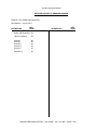
REVISION HISTORY BY DRAWING NUMBER
MANUAL: NAV 2000R Signal Generator
REVISION: 0 – July 26, 2007
DRAWING NO.
REV.
_LEVEL
DRAWING NO.
REV.
LEVEL
Safety and Regulatory 00
Table of Contents
00
Section I
Section II
Section III
Section IV
Section V
00
00
00
00
00
Appendix A
00
DRAWING REVISION HISTORY – NAV 2000R – JULY 26, 2007 – PAGE 1 OF 1
Aeroflex Operation Manual
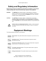
Safety and Regulatory Information
Review this product and related documentation to familiarize yourself with
safety markings and instructions before you operate this equipment.
WARNING
The WARNING notice denotes a hazard. It calls attention to a procedure,
practice, or the like, that, if not correctly performed or adhered to, could result in
personal injury. Do not proceed beyond a WARNING notice until the indicated
conditions are fully understood and met.
CAUTION
The CAUTION notice denotes a hazard. It calls attention to an operating
procedure, practice, or the like, which, if not correctly performed or adhered to,
could result in damage to the product or loss of important data. Do not proceed
beyond a CAUTION notice until the indicated conditions are fully understood and
met.
Caution (refer to accompanying documents). Attention – refer to the manual.
This symbol indicates that information about usage of a feature is contained in
the manual.
Equipment Markings
The following markings may appear on this equipment:
Direct current. This symbol indicates that the equipment requires direct current
input.
Alternating current. This symbol indicates that the equipment requires
alternating current input.
Both direct and alternating current. This symbol indicates that the equipment
requires either ac or dc input at the same connector.
3
Three-phase alternating current. This symbol indicates that the equipment
requires 3-phase ac input.
Earth (ground) terminal. This symbol indicates the ground (earth) terminal.
SAFETY AND REGULATORY INFORMATION
NAV 2000R – REVISION 0 – JULY 26, 2007 - PAGE 1
Aeroflex Operation Manual
Protective conductor terminal. This symbol indicates the protective ground
(earth) terminal.
Frame or chassis terminal. This symbol indicates the frame or chassis terminal
for connection to ground.
Equipotentiality. This symbol indicates an equipotentiality terminal.
On (Supply). This symbol indicates that the power line switch is ON.
Off (Supply). This symbol indicates that the power line switch is OFF.
Standby. This symbol indicates that the power line switch is in STANDBY.
Caution, risk of electric shock. Danger – high voltage.
Caution, hot surface. Danger – high temperature surface.
Caution (refer to accompanying documents). Attention – refer to the manual.
This symbol indicates that information about usage of a feature is contained in
the manual.
In-position of a bistable push control. This symbol indicates the in (on)
position of a bistable push control.
Out-position of a bistable push control. This symbol indicates the out (off)
position of a bistable push control.
CE Mark. ™ of the European Community.
Fuse Symbol. To indicate a fuse.
SAFETY AND REGULATORY INFORMATION
NAV 2000R – REVISION 0 – JULY 26, 2007 - PAGE 2
Aeroflex Operation Manual
Warnings
WARNING
Do not use the equipment in a manner not specified in this manual!
WARNING
Equipment should only be serviced by authorized personnel.
WARNING
To avoid fire hazard, use only a fuse identical in type, voltage rating, and current
rating as specified on the fuse rating label and/or in the manual.
Proper Power Cord
Use only the power cord and connector appropriate for the voltage and plug
configuration in your country. Use only a power cord that is in good condition.
Refer cord and connector changes to qualified service personnel.
Do Not Operate in Explosive Atmospheres
To avoid explosion, do not operate the equipment in an atmosphere of explosive
gas.
Do Not Attempt to Operate if Protection may be Impaired.
If the equipment appears damaged or operates abnormally, protection may be
impaired. Do not attempt to operate it. When in doubt, have the equipment
serviced.
Cleaning Warning
Keep the equipment dry to avoid electrical shock to personnel or damage to the
equipment. To prevent damage, never apply solvents to the equipment housing.
For cleaning, wipe the equipment with a cloth that is lightly dampened with water,
mild detergent, or alcohol. Do not use aromatic hydrocarbons, chlorinated
solvents, or methanol-based fluids.
Operating Position
Normal operating position is horizontal, on a flat surface. Vertical position is not
considered normal operation.
WARNING
This is a Safety Class 1 Product (provided with a protective earthing ground
incorporated in the power cord). The mains plug shall only be inserted in a
socket-outlet provided with a protective earth contact. Any interruption of the
protective conductor inside or outside of the product is likely to make the product
dangerous. Intentional interruption is prohibited.
WARNING
Equipment is not intended for wet locations. Miscellaneous liquids on or in the
equipment could cause hazardous conditions.
Safety Maintenance.
The operator should check the detachable power supply cord condition. The
equipment should not be operated if the mains inlet is cracked or broken. Any
obvious damage to the case (from a drop or fall) should be checked by service
personnel for loose or damaged parts inside. See parts lists for approved
replacement parts.
SAFETY AND REGULATORY INFORMATION
NAV 2000R – REVISION 0 – JULY 26, 2007 - PAGE 3
Aeroflex Operation Manual
WARNING TO SERVICE PERSONNEL
Ensure that power is disconnected before removal of any covers.
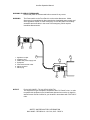
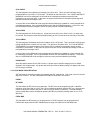
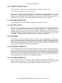
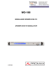
WARNING
The Power switch on the Front Panel is not the mains disconnect. Mains
disconnect is accomplished by disconnecting the detachable power supply cord
at the appliance coupler or at the mains plug. Ensure the power cord is easily
accessible and removable, in the event of an emergency, which requires
immediate disconnection.
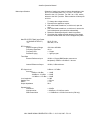
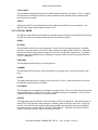
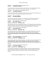
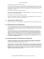
5
1.
2.
3.
4.
5.
6.
7.
7
3
4
Appliance coupler
Appliance inlet
Detachable power supply cord
Equipment
Fixed mains socket-outlet
Mains connector
Mains plug
1
6
NOTICE
2
For the NAV 2000R – TA Unit (JPN 01-0520-TA):
This equipment is type accepted in accordance with FCC Part 87 rules. In order
to operate this equipment in the United States (transmit an over the air signal) a
station license must be in effect for your location in accordance with FCC Part 87
rules.
SAFETY AND REGULATORY INFORMATION
NAV 2000R – REVISION 0 – JULY 26, 2007 - PAGE 4
Aeroflex Operation Manual
TABLE OF CONTENTS
SECTION I
GENERAL INFORMATION
SECTION
1.1
1.2
1.3
1.4
1.5
1.6
1.6
PAGE NUMBER
GENERAL INFORMATION .................................................................. 1-1
EQUIPMENT DESCRIPTION .............................................................. 1-1
TECHNICAL CHARACTERISTICS ...................................................... 1-1
UNITS AND ACCESSORIES SUPPLIED ............................................ 1-6
UNITS AND ACCESSORIES REQUIRED ........................................... 1-6
OPTIONAL EQUIPMENT ..................................................................... 1-6
SERVICE INFORMATION.................................................................... 1-6
SECTION II
INSTALLATION
2.1
2.2
2.3
2.4
GENERAL INFORMATION .................................................................. 2-1
UNPACKING AND INSPECTION OF EQUIPMENT............................ 2-1
EQUIPMENT INSTALLATION ............................................................. 2-1
POST INSTALLATION CHECK ........................................................... 2-1
SECTION III
OPERATION
3.1
3.2
3.3
3.4
3.5
3.5.1
3.5.2
3.5.3
3.5.4
3.5.4.1
3.5.4.2
3.5.4.3
3.5.4.4
3.5.4.5
3.5.5
3.5.6
3.5.7
3.5.8
3.5.9
3.5.10
3.5.11
3.5.12
3.5.13
3.5.14
3.5.15
3.5.16
3.5.17
GENERAL INFORMATION .................................................................. 3-1
FRONT PANEL DESCRIPTION........................................................... 3-1
REAR PANEL DESCRIPTION ............................................................. 3-2
POWER UP PROCEDURE.................................................................. 3-2
LOCAL USER INTERFACE ................................................................. 3-3
NAV 2000R MODES ............................................................................ 3-3
MENU LAYOUT DESCRIPTION.......................................................... 3-3
GETTING AROUND IN THE MENUS .................................................. 3-4
CHANGING FIELD DATA / ALPHANUMERIC .................................... 3-5
EDITING NUMERIC OR ALPHANUMERIC FIELDS ........................... 3-5
ENTERING FIELD VALUES WITH THE KEYPAD .............................. 3-6
TOGGLE FIELD EDITING.................................................................... 3-6
USING HOT KEYS ............................................................................... 3-6
RF LEVEL ENTRY ............................................................................... 3-7
VOR MODE FIELD DEFINITIONS....................................................... 3-7
VOR AUDIO CONTROL MODE (VORa) FIELD DEFINITION............. 3-9
LOCALIZER MODE FIELD DEFINITION ............................................. 3-10
LOC AUDIO CONTROL MODE (LOCa) FIELD DEFINITION ............. 3-13
GLIDESLOPE MODE FIELD DEFINITIONS........................................ 3-14
ADF MODE FIELD DEFINITIONS ....................................................... 3-15
MARKER BEACON MODE FIELD DEFINITION ................................. 3-17
COMMUNICATION MODE FIELD DEFINITION.................................. 3-18
SELCAL MODE .................................................................................... 3-19
UTILITY MENU..................................................................................... 3-21
EXTERNAL MODULATION MODE...................................................... 3-23
CALIBRATION MODE.......................................................................... 3-23
DISPLAY DEFINITION DURING POWER ON SEQUENCE ............... 3-24
TABLE OF CONTENTS - NAV 2000R – REVISION 0 – JULY 26, 2007 - PAGE TC-1
Aeroflex Operation Manual
SECTION III
OPERATION (Con't)
SECTION
3.5.18
3.6
3.6.1
3.6.2
3.7
3.8
PAGE NUMBER
STORING & RECALLING SETUPS..................................................... 3-24
REMOTE USER INTERFACE.............................................................. 3-24
GPIB REMOTE INTERFACE DESCRIPTION ..................................... 3-24
COMMAND LIST .................................................................................. 3-25
USING THE EXTERNAL AUDIO INPUT.............................................. 3-34
USING AUDIO OUTPUT ...................................................................... 3-35
SECTION IV
THEORY OF OPERATION
4.1
4.2
4.2.1
4.2.2
4.2.3
4.3
4.3.1
4.3.2
4.3.3
4.3.4
4.3.5
4.3.6
4.3.7
4.3.8
4.3.9
4.3.10
4.3.11
4.3.12
4.3.13
4.3.14
4.4
4.4.1
4.4.2
4.4.3
4.5
4.5.1
4.5.2
4.5.3
4.5.4
4.5.5
4.5.6
4.5.7
4.5.8
4.5.9
4.5.10
4.5.11
GENERAL INFORMATION .................................................................. 4-1
UNIT DESCRIPTION............................................................................ 4-1
FRONT PANEL .................................................................................... 4-1
REAR PANEL ....................................................................................... 4-1
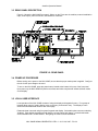
CHASSIS INTERIOR LAYOUT ............................................................ 4-1
FUNCTIONAL DESCRIPTION............................................................. 4-2
RF OUTPUT LEVEL............................................................................. 4-2
FREQUENCY ....................................................................................... 4-2
VOR SIGNAL GENERATOR................................................................ 4-2
ILS SIGNAL GENERATOR .................................................................. 4-2
COM SIGNAL GENERATOR ............................................................... 4-3
SYSTEM COMPUTER BOARD THEORY OF OPERATION............... 4-3
DSP BOARD THEORY OF OPERATION ............................................ 4-4
RF MODULATOR MODULE DESCRIPTION ...................................... 4-5
MODULATOR GENERAL OPERATIONAL DESCRIPTION................ 4-6
AUDIO BOARD OPERATION .............................................................. 4-6
RF MODULATOR BOARD OPERATION............................................. 4-7
PROGRAMMABLE STEP ATTENUATOR CIRCUIT ........................... 4-8
SYNTHESIZER .................................................................................... 4-8
REVERSE POWER PROTECTION MODULE OPERATION
(-50 UNIT WITH MOD STATUS 7 ONLY)............................................ 4-10
NAV 2000R SOFTWARE ..................................................................... 4-10
SELF TEST........................................................................................... 4-10
CALIBRATION...................................................................................... 4-11
MEMORY USAGE AND INITIALIZATION............................................ 4-11
DETAILED CIRCUIT DESCRIPTION................................................... 4-12
MOTHER BOARD CIRCUIT DESCRIPTION....................................... 4-13
SYSTEM COMPUTER (CPU) BOARD CIRCUIT DESCRIPTION....... 4-13
DSP BOARD CIRCUIT DESCRIPTION ............................................... 4-14
RF MODULATOR MODULE CIRCUIT DESCRIPTION....................... 4-15
RF MODULATOR MODULE BLOCK DIAGRAM ................................. 4-15
RF MODULATOR MODULE BUS INTERFACE CIRCUITRY
(AUDIO BOARD - A1) .......................................................................... 4-15
EXTERNAL AUDIO CONTROL ........................................................... 4-16
INTERNAL & EXTERNAL MODULATION SUMMING......................... 4-16
AUDIO HIGH/LOW INDICATION ......................................................... 4-16
% MODULATION LEVEL SET ATTENTUATOR ................................. 4-17
% MODULATION CENTERING & CALIBRATION .............................. 4-17
TABLE OF CONTENTS - NAV 2000R – REVISION 0 – JULY 26, 2007 - PAGE TC-2
Aeroflex Operation Manual
SECTION IV
THEORY OF OPERATION (Con't)
SECTION
4.5.12
4.5.13
4.5.14
4.5.15
4.5.16
4.5.17
4.5.18
4.5.19
4.5.20
4.5.21
4.5.22
4.5.23
4.6
4.7
4.7.1
4.7.2
4.7.3
4.7.4
4.8
PAGE NUMBER
VOLTAGE REFERENCE ..................................................................... 4-17
DETECTED AUDIO HI/LO INDICATION ............................................. 4-18
PROGRAMMABLE STEP ATTENUATOR CONTROL ........................ 4-18
RF MODUALTOR BOARD ................................................................... 4-18
MODULATING SIGNAL TEMP. COMPENSATION NETWORK ......... 4-18
AUDIO MODULATED AMPLIFIER ...................................................... 4-19
RF LEVELING AMPLIFIER .................................................................. 4-20
FIXED GAIN AMPLIFIERS................................................................... 4-20
DETECTOR .......................................................................................... 4-20
LPF & INTEGRATOR ........................................................................... 4-21
SCALING & RF LEVEL SET ................................................................ 4-21
RF HIGH/LOW INDICATION................................................................ 4-22
PROGRAMMABLE STEP ATTENUATOR........................................... 4-22
SYNTHESIZER CIRCUITS .................................................................. 4-22
REFERENCE/CONTROL BOARD CIRCUITS..................................... 4-22
RF/OUTPUT BOARD CIRCUITS ......................................................... 4-23
MAIN VCO ............................................................................................ 4-25
400 MHz VCO ...................................................................................... 4-25
REVERSE POWER PROTECTION
(-50 UNIT WITH MOD STATUS 7)....................................................... 4-25
SECTION V
MAINTENANCE INFORMATION
5.1
BILLS OF MAT, ASSY DWGS, SCHEMATICS & TEST PROCED ..... 5-1
APPENDIX A
GPIB COMMAND QUICK REFERENCE ............................................. A-1
TABLE OF CONTENTS - NAV 2000R – REVISION 0 – JULY 26, 2007 - PAGE TC-3
Aeroflex Operation Manual
SECTION I
GENERAL INFORMATION
1.1 GENERAL INFORMATION
The Aeroflex NAV 2000R generates ADF, MARKER BEACON, HF/VHF, COM and SELCAL signals for
test applications.
1.2 EQUIPMENT DESCRIPTION
The NAV 2000R VOR/ILS/COM Signal Generator contains necessary hardware and firmware to provide
modulated RF signals to verify operation of VOR navigational, ILS (Glideslope, Localizer, and Marker
Beacon), and COM communications LRU systems for aircraft. An external modulation signal can either
be summed with internal audio signals or separately controlled. The modulated RF output is connected
directly to the LRU. The NAV 2000R can be locally or remotely operated.
1.3 TECHNICAL CHARACTERISTICS
Mains Fuses
The equipment uses two type F, 1.6 A, 250 V, 5 mm X
20 mm fuses (A1F1 and A1F2).
To replace these fuses, which are located on the rear
panel inside the Appliance Inlet (A1FL1):
1. disconnect the appliance coupler.
2. With a flat blade screwdriver, or similar tool, open
the cover.
3. With a flat blade screwdriver, or similar tool, remove
the fuse holder/power input selection subassembly.
4. Replace fuse(s) with kind indicated above.
5. Replace the fuse holder/power input selection
subassembly so that voltage selected appears in
window when the cover is snapped into place.
Ac Power Source
The equipment is intended to operate from an ac power
source that will not apply more than 253 V ac between
the supply conductors or between either supply
conductor and ground. A protective ground connection
by way of the grounding conductor in the power cord is
required for safe operation.
Environmental Specifications
The environmental specifications are as follows.
Operating Temperature
5 °C to 40 °C.
Storage Temperature
-20 °C to +85 °C.
Relative Humidity
Maximum of 80% for temperatures up to 31 °C
decreasing linearly to 50% at 40 °C.
Operating Altitude
2 000 m maximum.
Size
14.5 cm H x 44.2 cm W x 49.0 cm D
(5.7” H x 17.4” W x 19.3” D)
NAV 2000R SIGNAL GENERATOR - REV. 0 – JULY 26, 2007 - PG 1-1
Aeroflex Operation Manual
Mass (Weight)
61.2 kg (135 lbs.)
Ventilation Requirements
Keep the ventilation openings clear.
IEC Overvoltage Category
II
Pollution Degree
1
Equipment Meets These Listed Standards
EN 61010-1 (IEC 61010-1)
EN 61328
EN 61326 Class A
Cables and Wires
1. It is recommended that all cables connecting to the
AUDIO OUTPUT (A3J5), EXTERNAL MOD INPUT
(A4A2P1), 10 MHZ OUT (A5A1J7), and 10 MHZ IN
(A5A1J6) terminals (ports) use M17/84-RG223
double shielded coaxial cable, or equivalent,
properly terminated to BNC connectors.
2. It is recommended that the cable connecting to the
RF OUTPUT (A1J1) terminals (port) use M17/75RG214 double shielded coaxial cable, or equivalent,
properly terminated to N connectors.
Warm Up Duration
30 min minimum for specified performance.
Nonvolatile Memory Life
10 years minimum data retention in the absence of
external power.
Data Input / Output
Compatible with IEEE Standard 488-1978
Electrical Specifications
Power Requirements
115/230 V
60/50 Hz
750 mA max, 70 W
NAV 2000R SIGNAL GENERATOR - REV. 0 – JULY 26, 2007 - PG 1-2
Aeroflex Operation Manual
Mains Input Selection
Selection of mains input range is done at the appliance inlet
(A1FL1) on the back panel. For 115 V ac ± 10%, set the
selector to the 115 V position. For 230 V ac ± 10%, set the
selector to the 230 V position. Either selection will accept 50
or 60 Hz.
To change the voltage selection:
1. Disconnect the appliance coupler.
2. With a flat blade screwdriver, or similar tool, open the
cover.
3. With a flat blade screwdriver, or similar tool, remove the
fuse holder/power input selection subassembly.
4. Rotate the assembly and push it back into position.
5. Check that the voltage selected appears in the voltage
selection window when the cover is snapped into place.
Max RF OUTPUT Safe Input Power
-50 (W/MOD STATUS 7)
-TA
50 W, 50 V dc
200 mW, 0 V dc
RF Frequency
Output Frequency Range
Frequency Resolution
Frequency Drift
Reference Aging
150 kHz to 450 MHz
10 Hz
± 2.5 ppm
± 1 ppm per year
Time Base
External Reference Input
Internal Reference Output
10 MHz ±2.5 ppm (BNC/female connector on
backpanel) -2 dBm to +20 dBm 5 V dc max
10 MHz, 0 dBm minimum.
RF Output level
Accuracy
0 dBm to -64 dBm
-64 dBm to -110 dBm
-110 dBm to -127 dBm
Level resolution
Settling Time
SWR
Output Impedance
0 dBm to -127 dBm
± 1.0 dB
± 2.0 dB
± 3.0 dB
0.1 dB
< 250 ms
< 1.5:1
50 Ω
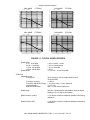
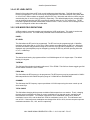
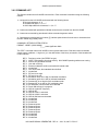
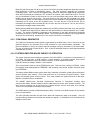
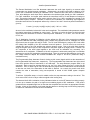
Spectral purity
Harmonics
Non-harmonics
SSB Phase Noise
< -30 dBc
< -60 dBc at > 5 kHz from carrier
< -115 dBc/Hz at > 25 kHz from carrier (CW only)
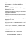
NAV 2000R SIGNAL GENERATOR - REV. 0 – JULY 26, 2007 - PG 1-3
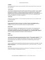
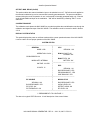
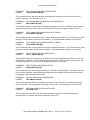
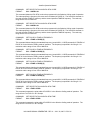
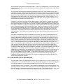
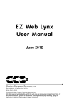
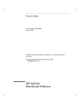
NAV 2000R
Carrier:
Aeroflex Operation Manual
(TYPICAL)
NAV 2000R
333 MHz
Carrier:
+0
−10
−20
+0
−10
−20
−30
−40
−30
−40
−50
−60
−70
−80
−90
−100
−110
−120
−130
−50
−60
−70
−80
−90
−100
−110
−120
−130
−140
10
100
1K
10K
100K
−140
10
single side band phase noise (dBc/Hz) vs. frequency (Hz)
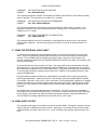
NAV 2000R
Carrier:
(TYPICAL)
Carrier:
−30
−40
−30
−40
−50
−60
−70
−80
−90
−100
−110
−120
−130
−50
−60
−70
−80
−90
−100
−110
−120
−130
100
1K
10K
1K
NAV 2000R
138 MHz
+0
−10
−20
10
100
10K
100K
single side band phase noise (dBc/Hz) vs. frequency (Hz)
+0
−10
−20
−140
(TYPICAL)
108 MHz
100K
single side band phase noise (dBc/Hz) vs. frequency (Hz)
−140
10
(TYPICAL)
75 MHz
100
1K
10K
100K
single side band phase noise (dBc/Hz) vs. frequency (Hz)
FIGURE 1-1: TYPICAL GRAPH FIGURES
Residual FM
0.15 - 56.25 MHz
56.25 - 112.50 MHz
112.50 - 225.00 MHz
225.00 - 450.00 MHz
Residual AM
VOR mode
Modulation tones
Frequencies
Frequency Accuracy
Frequency Adjustment Range
Distortion(audio)
9960 Hz FM deviation
< 25 Hz at 0.05 - 15 kHz
< 10 Hz Post Detection
< 16 Hz Noise BW
< 25 Hz
< 0.1% 0.05 - 15 kHz Noise BW
30 Hz reference, 30 Hz variable, 9960 Hz, and
1020 Hz IDENT
± 0.005%
± 10% Aux. Audio = 10 Hz -18000 Hz
< 0.1% THD
480 ± 1 Hz at default frequencies
Radial range
000.00 to 359.99 degrees (selectable at each 30 degree
heading or in 0.01 degree increments)
Radial accuracy (Audio)
± 0.01 degree relative to calibration standard used during
calibration.
Radial accuracy (RF)
± 0.05 degree relative to calibration standard used during
calibration.
NAV 2000R SIGNAL GENERATOR - REV. 0 – JULY 26, 2007 - PG 1-4
Aeroflex Operation Manual
Amplitude Modulation
Range (per tone)
1020 Hz IDENT
30 Hz variable
9960 Hz
Resolution
Overall accuracy
Tone distortion
(RF at default)
Total VOR demodulated error
LOCALIZER mode
Modulation tones
Frequencies
Frequency accuracy
Frequency adjustment Range
Distortion (audio)
90/150 Hz phase
Fixed
Variable Resolution
Variable Accuracy
Amplitude modulation
Range (per tone)
90 and 150 Hz
Default
Variable
1020 Hz
Default
Variable
Accuracy (sum of all tones)
Tone distortion
(RF at default)
total % mod not to exceed 99%
0-99%, Default 30%
0-99%, Default 30%
0-99%, Default 30%
0.01%
± 2% of setting for 10% to 95% AM
2% maximum
< ±0.05 degree of selected radial
90 Hz, 150 Hz, and 1020 Hz ident
± 0.005%
± 10% Aux. Audio = 10 Hz -18000 Hz
< 0.1% THD
0.0 ± 0.01 degree
0.01 degree
±0.05 degrees
total % mod not to exceed 99%
20%
0 to 99% in 0.01% increments
30%
0 to 99% in 0.01% increments
± 2% of setting for 10% to 95%
2% maximum
DDM
Default
Selectable settings
Variable range
Total system error
(audio + modulation)
GLIDESLOPE mode
Modulation tones
Frequencies
Frequency accuracy
Frequency adjustment range
Distortion (audio)
0.000 DDM
0.000, 0.046, 0.093, 0.155, 0.200 DDM
0.400 in 0.001 increments
±0.0003 @ 0 DDM
±0.0012 @ 0.046 DDM
±0.0021 @ 0.093 DDM
±0.0034 @ 0.155 DDM
±0.0053 @ 0.200 DDM
90 Hz, 150 Hz
± 0.005%
± 10%
< 0.1% THD
NAV 2000R SIGNAL GENERATOR - REV. 0 – JULY 26, 2007 - PG 1-5
Aeroflex Operation Manual
90/150 Hz phase
Fixed
Variable resolution
Variable accuracy
Amplitude modulation
Range (per tone)
90 and 150 Hz
Default
Variable
Accuracy (sum of all tones)
Tone distortion
(RF at default)
DDM
Default
Selectable settings
Variable range
Total system error
(audio + modulation)
0.0 ± 0.01 degree
0.01 degree
± 0.05 degrees
total % mod not to exceed 99%
40%
0 to 99% in 0.01% increments
± 2% of setting for 10% to 95%
2% maximum
0.000 DDM
0.000, 0.045, 0.091, 0.175, 0.400 DDM
0.800 in 0.001 increments
± 0.0003 @ 0 DDM
± 0.0012 @ 0.045 DDM
± 0.0021 @ 0.091 DDM
± 0.0038 @ 0.175 DDM
± 0.0083 @ 0.400 DDM
ADF
Modulation tone
Preset
Variable
Frequency accuracy
Distortion (audio, 10 Hz
to 10 kHz)
Amplitude modulation
Range
Preset
Variable
Accuracy
MARKER BEACON
Modulation tone
Frequencies
Frequency Adjustment Range
Adjustment Resolution
Frequency Accuracy
Distortion (audio only)
Amplitude modulation
Range
Preset
Variable
1000 Hz
10 Hz to 18 kHz (0.1 Hz increments)
± 0.005%
< 0.1% THD
95%
0 to 99% in 0.01% increments
± 2% of setting for 10% to 95%
400/1300/3000 Hz
10 Hz to 18 kHz
0.1 Hz
± 0.005%
< 0.1% THD
95%
0 to 99% in 0.01% increments
NAV 2000R SIGNAL GENERATOR - REV. 0 – JULY 26, 2007 - PG 1-6
Aeroflex Operation Manual
COMM
Modulation tones (two tones selectable)
Preset
Variable
Frequency accuracy
Distortion (audio, 10 Hz
to 10 kHz)
Amplitude modulation
Range
Preset @ 1000 Hz
Variable 10 to 18 kHz
Accuracy
External modulation
Input impedance
Maximum modulation depth
Modulation distortion
Modulation bandwidth
Input level
1000 Hz and 2000 Hz
10 Hz to 18 kHz (0.1 Hz increments)
± 0.005%
< 0.1% THD
total % mod not to exceed 99%
30%
0 to 99% in 0.01% increments
± 2% of setting for 10% to 95%
5 kΩ
99%
2% maximum
10 Hz to 22 kHz
1 V peak
Morse Code (ident) - Programmable in VOR, Localizer or ADF mode
Max Length
6 characters
Rate
programmable
Dot/Dash/spacing times
individually programmable
Audio Output Level
1.414 ± 0.025 V rms into 600 Ω. Adjustable downward
in audio modes
1.4 UNITS AND ACCESSORIES SUPPLIED
NAV 2000R VOR/ILS/COM Generator
NAV 2000R CD Operation Manual
Detachable Power Supply Cord
JPN 01-0520-50
JPN E6-0520-5A
1.5 UNITS AND ACCESSORIES REQUIRED
The NAV 2000R requires the following items to be interconnected to a remotely operated test equipment
environment.
ITEM
DESCRIPTION
TYPE
1
GPIB Cable
It is recommended that a HP type 10833X
braided shield cable, or equivalent, be used.
NAV 2000R SIGNAL GENERATOR - REV. 0 – JULY 26, 2007 - PG 1-7
Aeroflex Operation Manual
1.6 OPTIONAL EQUIPMENT
ITEM
DESCRIPTION
TYPE
1
Extender Board
JPN 20-5760-00
1.7 SERVICE INFORMATION
If you have any questions regarding service, you may contact the factory at the address listed below:
Aeroflex
400 New Century Parkway
New Century, KS 66031
Phone: (913) 764-2452
Fax: (913) 782-5104
http://www.aeroflex.com
NAV 2000R SIGNAL GENERATOR - REV. 0 – JULY 26, 2007 - PG 1-8
Aeroflex Operation Manual
SECTION II
INSTALLATION
2.1 GENERAL INFORMATION
This section contains information relating to the unpacking, inspection, and installation of the
Aeroflex NAV 2000R VOR/ILS/COM Generator.
2.2 UNPACKING AND INSPECTION OF EQUIPMENT
Exercise extreme care when unpacking the unit and accessories. Make a visual inspection of the NAV
2000R for evidence of damage incurred during shipment. If a claim for damage is to be filed, save the
shipping container to substantiate the claim. When all the equipment has been unpacked, return all the
packing material to the container for future use in storing and shipping the equipment.
2.3 EQUIPMENT INSTALLATION
The NAV 2000R VOR/ILS/COM generator is manufactured as a bench test unit, but may be rack
mounted using optional rack mount handle flanges.
2.4
POST INSTALLATION CHECK
After completing installation of the Aeroflex NAV 2000R VOR/ILS/COM Generator, a power-up self-test
verifies its operation. The NAV 2000R display will identify any problems found during the power-up selftest.
NAV 2000R SIGNAL GENERATOR - REV. 0 – JULY 26, 2007 - PG 2-1
Aeroflex Operation Manual
SECTION III
OPERATION
3.1 GENERAL INFORMATION
This Section describes how to operate the NAV 2000R VOR/ILS/COM generator. It contains information
for an initial inspection, general operating information, and local and remote operation. The NAV 2000R
can be operated using either the local user interface or the remote user interface. The local user
interface uses the front panel keypads and display. The remote interface uses a General Purpose
Interface Bus (GPIB). Throughout this manual, GPIB shall be used to mean an interface bus conforming
to IEEE Standard 488-1978, "Standard Digital Interface For Programmable Instrumentation."
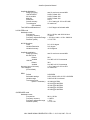
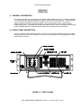
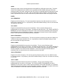
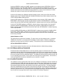
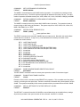
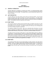
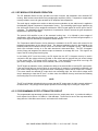
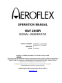
3.2 FRONT PANEL DESCRIPTION
Figure 3-1 shows the NAV 2000R front panel. Shown on the Figure are the display (including its fields),
the mode select keypad, cursor keypad and select key, hot keys keypad, numeric keypad, power switch,
and RF output connector.
FIGURE 3-1: FRONT PANEL
NAV 2000R SIGNAL GENERATOR - REV. 0 – JULY 26, 2007 - PG 3-1
Aeroflex Operation Manual
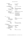
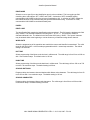
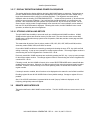
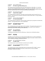
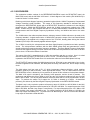
3.3 REAR PANEL DESCRIPTION
Figure 3-2 shows the NAV 2000R rear panel. Shown on the Figure are the modules, external modulation
input, audio output, power connection, and GPIB bus connector.
FIGURE 3-2: REAR PANEL
3.4 POWER UP PROCEDURE
Before turning on the power to the NAV 2000R, ensure that the proper mains power is applied. Configure
the unit for the input voltage to be used.
To turn on the NAV 2000R, press the power button located at the bottom left corner of the front panel.
Upon power up, the NAV 2000R will perform a self-test and when complete will indicate self-test results
on the display.
3.5 LOCAL USER INTERFACE
Local operation of the NAV 2000R consists of using the display and keypads for entry. Four groups of
keypads allow control of mode, display cursor, quick entry, and numeric entry. The display is menu
driven with selectable data fields on each menu page.
Parametric data is entered using front panel keypads and display. Selectable options are surrounded by
"bubbles". Each bubble represents a field that the user may select and change. Located underneath
each selectable field is a field identifier. Navigating the menus is discussed below.
NAV 2000R SIGNAL GENERATOR - REV. 0 – JULY 26, 2007 - PG 3-2
Aeroflex Operation Manual
3.5.1 NAV 2000R MODES
The NAV 2000R local operation is menu driven through the use of mode menu pages. There are six
generator modes and three utility modes. Each top level generator mode menu is accessed by pressing
the corresponding mode menu select key. With the exception of G/S, the LOC/GS key toggles between
LOC and G/S modes. These are aligned vertically and to the right of the display. The main generator
modes are: VOR, LOCalizer (LOC), Glide Slope (G/S), ADF, MarKeR beacon (MKR) and
COMmunications (COM). The utility menu can be accessed by pressing and holding any of the generator
mode select keys, except for the LOC/GS key, for two seconds. Two additional modes, External
Modulation Mode (EMM) and CALibration mode (CAL), are accessible from the utility menu. Also, VOR
and LOC modes have alternate control modes to allow control of their audio composite output signals.
These modes, VORa and LOCa, are accessed by selecting the audio control mode bubble from within
their 1st page. The SELCAL mode is accessed from the SELCAL bubble in PAGE 1 of the COM mode
menus.
3.5.2 MENU LAYOUT DESCRIPTION
Every display menu page can be broken into four different partitions: the Selected Mode Region, the
Status Line Region, the Prompt Line Region, and the Field Entry Region.
On each menu page, there are multiple fields. If more than one page is needed to access all fields of a
given mode, one of the fields will be the next page field.
DISPLAY REGION: Selected Mode Display
The Mode Select region is located in the upper left-hand corner of the display. This region indicates the
NAV 2000R current mode of operation. Distinguishing it from the other regions, the selected mode region
is displayed using inverse video. The character assignments for each mode are:
MODE
VOR
VOR audio control
Localizer
Localizer audio control
Glideslope
ADF
Marker Beacon
Communication
Ext. Modulation Mode
Calibration
Selective Calling
ABBREVIATION
VOR
VORa
LOC
LOCa
G/S
ADF
MKR
COM
EMM
CAL
SCL
NAV 2000R SIGNAL GENERATOR - REV. 0 – JULY 26, 2007 - PG 3-3
Aeroflex Operation Manual
DISPLAY REGION: Status Line
The status line enunciates certain NAV 2000R status conditions by using status flags. These
flags are made from grouped alphanumeric characters. In some cases the annunciation involves
flashing to attract attention. The flags, and their description, are detailed in this section.
EDIT ENUNCIATOR
The EDIT flag is enunciated whenever the user is editing a field.
VAL FLAG
The VAL flag is displayed whenever field values are set to a non-standard value, as defined by
the current system mode of operation. For example, it would be set during VOR mode when the
user requests an audio frequency deviating from the standard VOR frequencies.
REGXX or DEFLT FLAG
The REGXX flag is displayed whenever the user has stored or recalled a NAV 2000R setup
register. For example, after the user has recalled setup #1, the status line would display the
setup register flag REG01. When register # 00 is recalled, DEFLT is displayed indicating that the
NAV 2000R has been set to its factory default settings.
REMOTE FLAG
This flag is set anytime a remote application program has commanded the NAV 2000R via the
GPIB bus. During remote operation all front panel keyboard controls are locked out. The
CLR/LCL key, the only key recognized during remote mode, will force the system back to local
control.
EM∑
Indicates that an audio signal applied to the EXTERNAL MOD INPUT will be summed with
internal audio and applied to the AM modulator.
DISPLAY REGION: Prompt line
The prompt line region is located directly below the status line and displays special warnings or
errors that may arise during editing and controlling of the NAV 2000R.
3.5.3 GETTING AROUND IN THE MENUS
All front panel user inputs to the NAV 2000R are entered through selection of menu page fields. Each
mode of operation has a set of pre-defined user programmable items. These items are programmed
through the menu page display fields. VOR, LOC, G/S, and ADF generator modes have multiple menu
pages which provide access to all modifiable items. To access the next page, a "NEXT PAGE" menu
field is provided.
To display pages of the VOR, LOC, G/S, ADF, MKR, or COM menus, the appropriate mode select key is
pressed. (The mode select keypad is aligned along the right side of display). To move between different
mode pages for VOR, LOC, G/S and ADF use the cursor keypad to highlight the "NEXT PAGE" field and
press SEL (select).
NAV 2000R SIGNAL GENERATOR - REV. 0 – JULY 26, 2007 - PG 3-4
Aeroflex Operation Manual
To display the utility menu, any one of four generator mode keys [VOR, ADF, MKR, or COM] is pressed
and held down for two seconds. The external modulation (EMM) mode and the calibration (CAL) mode
can be entered from the utility menu by selecting the corresponding option on the menu. Pressing the
number of the utility menu item will immediately select the menu option. Alternatively, the arrow keys can
be used to move up and down the list until the desired item is highlighted and then the select (SEL) or
enter (ENT) keys can be pressed to activate the selection. Further discussion of the Utility Menu may be
found in Section 3.5.13.
To change the contents of a field, the cursor keypad is used to highlight the desired field. The user may
change the data of the currently selected field in a manner which is dependent upon the type of data the
field contains. There are four types of fields: Numeric, alphanumeric, discrete toggle, and next page.
3.5.4 CHANGING FIELD DATA / ALPHANUMERIC
3.5.4.1 EDITING NUMERIC OR ALPHANUMERIC FIELDS
A Numeric menu field (any field containing a numeric value) can be modified using either the cursor keys
or numeric keypad. This section details the use of the cursor keys to edit a field of existing data. The
cursor keys may be used to edit existing field data. To edit a field, press the SEL key while the field of
interest is highlighted.
Upon pressing the SEL key when a numeric or an alphanumeric field is highlighted, the edit mode is
entered and enunciated by the EDIT prompt. Within the field selected for edit is a cursor, two blinking
arrows, which indicates which character location is currently being edited.
The left and right arrow keys may be used to force the cursor to the character just left or right of the
current cursor position. This allows the user to alter any digit or character within the field. If the user
presses a numeric keypad button while editing, the digit will automatically be placed at the current cursor
location.
A character under edit may also be changed by pressing the up or down arrow keys to advance to the
next character or previous character, respectively. For numeric fields, the characters can be 0 - 9 and for
alphanumeric fields, A through Z, 0 through 9, and the space character.
When editing numeric digits using the cursor, if the digit changes from 9 to 0 then a 1 is carried to the
next significant digit. When changing alphanumeric digits with the cursors, the display will scroll through
the 0 through 9 digits, A through Z, and the space character before starting over at 0.
The CLR key can be pressed to restore the original value of the field being cursor edited. To terminate
cursor editing, press the SEL or ENT keys.
While editing, if the value of the numeric data moves outside its standard setting, two asterisks ('*') are
displayed, one on each side of the field. The NAV 2000R output signal changes immediately during
editing. This enables real time skewing of numeric parameters.
If the data in the numeric field being edited is at its lower limit then further decrementing with the down
arrow cursor key will have no effect and the message "VALUE LIMITED TO MINIMUM" will appear
briefly on the status line. If the data in the numeric field being edited is at its upper limit then further
incrementing with the up arrow cursor key will have no effect and the message "VALUE LIMITED TO
MAXIMUM" will appear briefly on the status line.
NOTE:
Numeric entry starts to the right side of the field and works left. However, alphanumeric entry starts to
the left and works right.
NAV 2000R SIGNAL GENERATOR - REV. 0 – JULY 26, 2007 - PG 3-5
Aeroflex Operation Manual
3.5.4.2 ENTERING NUMERIC FIELD VALUES WITH THE KEYPAD
Numeric field values can be entered directly using the numeric keypad. To modify a numeric field with
the numeric keypad the field is first selected using the cursor keys. The entry begins with a depression of
the numeric keypad digit. The previous numeric field value will blank and the new numeric digit, the one
which caused the edit entry, will be placed right justified. Each successive numeric key pressed will shift
left and append the new key to the right-most character position. This append shifting will be allowed to
continue for the full field width. If the user tries to enter more digits than will fit within the field, the leftmost
character will be truncated.
Pressing the ENT (enter) key terminates the number entry. The CLR (clear) key erases the field allowing
a number to be reentered. The arrow and edit keys will be ignored during numeric keypad entry. If the
user presses the ENT key when the field is cleared of all numeric data, the field is restored to the value
prior to edit mode entry. After the enter key is pressed, the system terminates edit mode.
After entering a numeric value, if the value of the numeric data moves outside its standard setting, two
asterisks ('*') are displayed, one on each side of the field.
If the data entered into the numeric field is less than the minimum acceptable lower limit, the field will be
set to its lower limit and the message "VALUE LIMITED TO MINIMUM" will appear briefly on the status
line. If the data entered into the numeric field is greater than the maximum acceptable upper limit, the
field will be set to its upper limit and the message "VALUE LIMITED TO MAXIMUM" will appear briefly on
the status line.
3.5.4.3 TOGGLE FIELD EDITING
With toggle field editing, the field data toggles between items in a list. The list will be two or more items.
To change a toggle field, the desired field is first highlighted using the cursor keypad. Then, the field
contents are changed when the SEL (select) key is pressed. Items can be toggled by pressing the select
key successively. The list toggles circularly so when the end of the list is reached, the first item will again
be displayed.
The numeric keys of the numeric keypad have no function during toggle editing.
3.5.4.4 USING HOT KEYS
"HOT KEYS" provide a quick method to modify bearing or DDM to a standard setting. The keys are only
recognized during VOR, LOC and G/S modes.
During the VOR mode, the hot keys allow the user to step through standard bearing check points without
having to edit the bearing field. Anytime the VOR mode is selected, the user may press any degree key
to automatically set the bearing field contents. Twelve different bearing settings are provided, these are:
0, 30, 60, 90, 120, 150, 180, 210, 240, 270, 300, and 330 degrees.
If LOC or G/S is the current mode, pressing one of the hot keys will automatically set the DDM to a preset
value. The standard DDM keys for G/S are .000, .045, .091, .175, and .400. The standard DDM keys for
LOC are .000, .046, .093, .155, and .200. If a DDM hot key is pressed which is not a standard DDM for
the current mode the DDM value will be accepted but the message "NON-STANDARD DDM VALUE" will
appear.
Pressing the 90 Hz or 150 Hz hot keys will toggle the indicated tone off or on.
NAV 2000R SIGNAL GENERATOR - REV. 0 – JULY 26, 2007 - PG 3-6
Aeroflex Operation Manual
3.5.4.5 RF LEVEL ENTRY
Most all of the modes have an RF level control bubble associated with them. This field allows the RF
level to be programmed. The RF level may be programmed with 1/10th dBm resolution using either dBm
or uV/mV units. DBm numbers are entered using the ENT key. Microvolts and millivolt numbers may be
entered using the uV and mV keys (STO/RCL) respectively. The default displayed units (normally dBm)
may be changed by pressing the SEL key and then pressing either the uV, mV, or dBm keys. The RF
level field is "global" to the other modes which control RF level. That is, if the RF level is changed in one
mode, it is changed for all the other modes alike.
3.5.5 VOR MODE FIELD DEFINITIONS
VOR test mode is entered by pressing and releasing the VOR mode button. This mode is used to test
and align VOR receivers. The VOR mode parameter fields are described in this section.
PAGE 1:
RF LEVEL
This field allows the RF level to be programmed. The RF level may be programmed with 1/10th dBm
resolution using either dBm or uV/mV units. DBm numbers are entered using the ENT key. Microvolts
and millivolt numbers may be entered using the uV and mV keys (STO/RCL) respectively. The default
displayed units (normally dBm) may be changed by pressing the SEL key and then pressing either the
uV, mV, or dBm keys.
BEARING
The desired omni bearing is programmed from 0 to 359.99 degrees in 0.01 degree steps. The default
bearing is 0 degrees.
TO/FROM
This field specifies whether the bearing reference is TO or FROM. This field is a discrete toggle type field
and the default reference is set to 'FROM'.
FREQ. MHz
This field allows the RF frequency to be programmed. The RF frequency may be programmed in 0.00001
MHz steps within the NAV 2000R frequency range of 0.15000 MHz to 450.00000 MHz.
CHANNEL
This field steps the RF frequency output up and down in 50 KHz steps using the cursor control up and
down arrow keys.
TOTAL %MOD
This field allows changing all the percent modulation fields respective to one another. That is, changing
the total percent modulation will allow all current modulations to be changed equally, maintaining the
ratios between one another. For example, suppose the 30 Hz modulation is set to 30%, 9960 Hz
modulation is set to 20%, and the ident tone 1020 Hz modulation is set to 10%. This indicates a total
sum of 60%. If the total percent modulation was changed from 60% to 30%, the new component percent
modulations would be 15%, 10%, and 5% respectively.
NAV 2000R SIGNAL GENERATOR - REV. 0 – JULY 26, 2007 - PG 3-7
Aeroflex Operation Manual
AUDIO
Selecting the audio control mode field places the NAV 2000R into VOR audio control mode. The audio
control mode, designated as the "VORa" mode, commands the NAV 2000R to allow the VOR audio
composite output to be varied. Within this mode, RF control is not allowed and the RF attenuator is fixed
for a minimum output level of -127 dBm. Also, no identification coding is allowed. The alternate VOR
mode of operation will continue until the VOR button is pushed while the VORa control page is selected.
PAGE 2:
30 Hz FREQUENCY
Programs the 30 Hz frequency. The user may specify a frequency from within the 24.0 Hz to 36.0 Hz
range, with a resolution of 0.1 Hz. Any frequency, other than the default setting of 30.0 Hz, will cause the
VAL flag to be enunciated.
30 Hz %MOD
Programs the desired 30 Hz tone percent of modulation. This is a numeric field type and is
programmable from 0 to 99% in 0.01% steps. The default for this field is 30%. The "VALUE LIMITED TO
MAXIMUM" error will be displayed if the user tries to enter a 30 Hz percent modulation value causing the
total modulation to be more than 99% modulation. In this case, the system limits the 30 Hz modulation
field to a value that forces all modulation percents to total 99%.
9960 Hz FREQUENCY
Programs the 9960 Hz center frequency. The user may specify a frequency from within the 7968.0 Hz to
11952.0 Hz range, with a resolution of 0.1 Hz. Any frequency, other than the default setting of 9.960
KHz, will cause the VAL flag to enunciate.
9960 Hz %MOD
Programs the desired 9960 Hz tone percent of modulation. This is a numeric field type and is
programmable from 0 to 99% in 0.01% steps. The default for this field is 30%. The "VALUE LIMITED TO
MAXIMUM" error will be displayed if the user tries to enter a 9960 Hz percent modulation value causing
the total modulation to be more than 99% modulation. In this case, the system limits the 9960 Hz
modulation field to a value that forces all modulation percents to total 99%.
1020 Hz FREQUENCY
Programs the 1020 Hz frequency. The user may specify a frequency from 10.0 Hz to 18000.0 Hz with
0.1 Hz step resolution. Any frequency, other than the default setting of 1020.0 Hz, will cause the VAL flag
to enunciate.
1020 Hz %MOD
Programs the desired 1020 Hz tone percent of modulation. This is a numeric field type and is
programmable from 0 to 99% in 0.01% steps. The "VALUE LIMITED TO MAXIMUM" error will be
displayed if the user tries to enter a 1020 Hz percent modulation value greater than 99% or a modulation
value causing the total modulation to be more than 99% modulation. In this case, the system will limit the
1020 Hz modulation to a value that causes all modulation percents to total 99%.
NAV 2000R SIGNAL GENERATOR - REV. 0 – JULY 26, 2007 - PG 3-8
Aeroflex Operation Manual
IDENT MODE
Allows the user to specify how the identification tone is to be modulated. This is a toggle type field
containing three valid options: OFF, CODE, and TONE. A selection of OFF, the default setting,
commands the NAV 2000R to force the percent of modulation to 0%. A selection of CODE, causes the
NAV 2000R to Morse code modulate using the specified identification string. A selection of TONE,
commands the NAV 2000R to modulate a steady tone.
PAGE 3:
IDENT CODE
The identification field contains the identification string transmitted. The field uses the alphanumeric field
entry method. The characters allowed in the string are 0 - 9, or A - Z. The maximum number of
characters allowed is six. The default for this field is the ASCII string "JCAIR". The "space" character
may be entered either at the beginning or end to allow entry of character strings shorter than six.
WORD RATE
Allows the programming of the repetition rate at which the morse code identifier is transmitted. The valid
range for the field is from 1 to 65 seconds programmable with 0.1 second step resolution. The default
setting is 30 seconds.
DOT TIME
Allows programming of the Morse code dot time in milliseconds. The valid range is from 50 ms to 250 ms
with 1 ms resolution steps. The default value is 150 ms.
DASH TIME
Allows programming of the Morse code dash time in milliseconds. The valid range is from 150 ms to 750
ms with 1 ms resolution steps. The default setting is 450 ms.
SPACING DOT/DASH
Programs delay time between dots and dashes within Morse code characters. The valid range is from 50
ms to 250 ms with 1 ms resolution steps. The default setting is 150 ms.
SPACING CHARACTER
Programs delay time between Morse code characters. The valid range is from 50 ms to 250 ms with 1
ms resolution steps. The default setting is 450 ms.
NAV 2000R SIGNAL GENERATOR - REV. 0 – JULY 26, 2007 - PG 3-9
Aeroflex Operation Manual
3.5.6 VOR AUDIO CONTROL MODE (VORa) FIELD DEFINITION
The VOR audio control mode, VORa, is entered by pressing and releasing the SEL key while the AUDIO
control mode field, on VOR page 1, is selected. This mode allows the user to specify the NAV 2000R
audio output signal level using volts RMS. No RF level control is allowed while within this mode of
operation.
COMPOSITE AUDIO CONTROL:
AUDIO LEVEL
This field allows the audio signal level to be changed. The value entered represents Vrms of the VOR
composite signal with both 30 Hz and 9960 Hz signals selected on.
BEARING
The desired omni bearing is programmed from 0 to 359.99 degrees in 0.01 degree steps. The default
bearing is 0 degrees.
TO/FROM
Specifies whether the bearing reference is TO or FROM. This field is a discrete toggle type field and the
default reference is set to 'FROM'.
30 Hz MOD
Specifies whether the 30 Hz signal is to be modulated. The field toggles between ON and OFF whenever
the SEL key is pressed while the field is selected.
9960 Hz MOD
Specifies whether the 9960 Hz signal is to be modulated. The field toggles between ON and OFF
whenever the SEL key is pressed while the field is selected.
3.5.7 LOCALIZER MODE FIELD DEFINITION
Localizer test mode is entered by pressing and releasing the LOC mode select button. This mode is used
to test and align the Localizer portion of ILS equipment.
PAGE 1:
RF LEVEL
This field allows the RF level to be programmed. The RF level may be programmed with 1/10th dBm
resolution using either dBm or uV/mV units. DBm numbers are entered using the ENT key. Microvolts
and millivolt numbers may be entered using the uV and mV keys (STO/RCL) respectively. The default
displayed units (normally dBm) may be changed by pressing the SEL key and then pressing either the
uV, mV, or dBm keys.
NAV 2000R SIGNAL GENERATOR - REV. 0 – JULY 26, 2007 - PG 3-10
Aeroflex Operation Manual
DDM
Programs the %MOD of the 90 and 150 Hz tones. The valid entry range for this field is from .000 to .400
DDM (Difference in Depth of Modulation) with .001 resolution. The NAV 2000R computes the percent of
modulation ratio between the 90 and 150 Hz required to produce the commanded DDM. The percent of
modulation of each tone will be set to the proper ratio forcing both tones to total the standard modulation
of 40%. The default value for this field is .000 DDM, 20% modulation for each tone.
When a valid Localizer DDM "hot" key is pressed, the DDM will automatically be accepted. If a G/S DDM
"hot" key is pressed, the system will accept it and will display, momentarily on the prompt line, the
warning message: "NON-STANDARD DDM VALUE". Pressing the 90 or 150 Hz "hot" key will alternately
shut off or turn on that tone to allow quick testing of a drop out of either tone at preset DDMs.
LEFT/RIGHT
Specifies whether the Localizer reference is either LEFT/150 or RIGHT/90. When this toggle type field is
selected, the current 90 and 150 Hz %MOD data fields are switched. The default value is LEFT/150.
FREQ. MHz
This field allows the RF frequency to be programmed. The RF frequency may be programmed in
0.00001 MHz steps within the NAV 2000R frequency range of .15 MHz to 450 MHz.
CHANNEL
This field steps the RF frequency output up and down in 50 kHz steps using the cursor control up and
down arrow keys.
TOTAL %MOD
This field allows changing all the percent modulation fields respective to one another. That is, changing
the total percent modulation will allow all current modulations to be changed equally, maintaining the
ratios between one another.
AUDIO
Selecting the audio control mode field alters the NAV 2000R's Localizer mode of operation. The audio
control mode, designated as the "LOCa" mode, commands the NAV 2000R to allow the Localizer audio
composite output to be varied. Within this mode, RF control is not allowed and the RF attenuator is fixed
for a minimum RF output level of -127 dBm. Also, no identification coding is allowed. The alternate LOC
mode of operation will continue until the LOC button is pushed while the LOCa control page is selected.
PAGE 2:
90 Hz FREQUENCY
Programs the 90 Hz frequency. A frequency from 72.0 Hz to 108.0 Hz in 0.1 Hz step may be entered.
Any frequency, other than the default setting of 90.0 Hz, will cause the VAL flag to enunciate.
NAV 2000R SIGNAL GENERATOR - REV. 0 – JULY 26, 2007 - PG 3-11
Aeroflex Operation Manual
90 Hz %MOD
Programs the modulation percentage of 90 Hz tone. This is a numeric field type and is programmable
from 0 to 99% in 0.01% steps. The default for this field is 20%. The "VALUE LIMITED TO MAXIMUM"
error is displayed if a 90 Hz modulation percentage causes the total modulation percentage, the sum of
percent modulation of the 90 Hz, 150 Hz, and the ident tone, to exceed 99%. In this case, the system
limits the 90 Hz modulation percentage to a value that forces all modulation percents to total 99%.
A current value for the DDM field will be computed and the field will be updated for the newly entered 90
Hz percent modulation data. If the sum of the 90 and 150 Hz percent modulation fields does not add to
40, the DDM field will display --- in the field and the modulation fields will be highlighted by an * on both
sides.
150 Hz FREQUENCY
Programs the 150 Hz frequency. A frequency from 120.0 Hz to 180.0 Hz in 0.1 Hz steps may be entered.
Any frequency, other than the default setting of 150.0 Hz, will cause the VAL flag to enunciate.
150 Hz %MOD
Programs the modulation percentage for 150 Hz tone. This is a numeric field type and is programmable
from 0 to 99% in 0.01% steps. The default for this field is 20%. The "VALUE LIMITED TO MAXIMUM"
error will be displayed if the 150 Hz modulation percentage is set to a value which causes the total
modulation to be more than 99%. In this case, the system limits the 150 Hz modulation field to a value
that forces all modulation percents to total 99%.
A current value for the DDM field will be computed and the field will be updated for a newly entered 150
Hz percent modulation data. If the computed DDM exceeds .400, the DDM field will display --- in the
field. Also, the LEFT/RIGHT field will be changed to reflect a newly entered percent of modulation field.
1020 Hz FREQUENCY
Programs the 1020 Hz frequency. A frequency from 10.0 Hz to 18000.0 Hz in 0.1 Hz steps may be
entered. Any frequency, other than the default setting of 1020.0 Hz, will cause the VAL flag to enunciate.
1020 Hz %MOD
Programs the 1020 Hz tone modulation percentage. This is a numeric field type and is programmable
from 0 to 99% in 0.01% steps. An entry of 0% modulation commands the NAV 2000R not to modulate
the ident tone. The VAL flag will be set when any value, other than the default value of 20%, is entered.
The "VALUE LIMITED TO MAXIMUM" error will be displayed if a 1020 Hz modulation percentage causes
the total modulation to be more than 99%. In this case, the system will limit the 1020 Hz modulation to a
value that causes all modulation percents to total 99%. If a 90 or 150 Hz modulation percentage causes
the total modulation percentage to exceed 99%, the system will adjust the desired 1020 Hz modulation
percentage to realize a total modulation percentage of 99%.
PHASE SHIFT
Allows alteration of the phase between the 90 Hz and 150 Hz tones. The phase may be specified
ranging from 0 to 359.99 degrees in 0.01 degree steps. Any phase shift value, other than the default
setting of 0 degrees, will cause the VAL flag to enunciate.
NAV 2000R SIGNAL GENERATOR - REV. 0 – JULY 26, 2007 - PG 3-12
Aeroflex Operation Manual
IDENT MODE
The ident mode field selects the identification tone modulation method. This is a toggle field containing
three valid options: OFF, CODE, and TONE. A selection of OFF, the default setting, commands the unit
to force the percent of modulation to 0%. Selecting CODE, causes the unit to Morse code modulate the
specified identification string. And a selection of TONE, commands the NAV 2000R to modulate a 1020
Hz tone.
PAGE 3:
IDENT CODE
Allows modification to the identification string transmitted. The field uses the alphanumeric field entry.
The characters allowed in the string are 0-9, A-Z, and the space. Characters lengths of 1 to 6 are
allowed. The default for this field is the string "JCAIR".
WORD RATE
Allows programming of time between each identification word. The valid range for the field is from 1 to
65 seconds programmable in 0.1 second steps. The default setting is 30 seconds.
DOT TIME
Allows programming of Morse code dot time in milliseconds. The valid range is from 50 ms to 250 ms in
1 ms steps. The default value is 150 ms.
DASH TIME
Allows programming of Morse code dash time in milliseconds. The valid range is from 150 ms to 750 ms
in 1 ms steps. The default setting is 450 ms.
SPACING DOT/DASH
Allows programming of delay time between Morse code dots and dashes. The valid range is from 150
ms to 750 ms in 1 ms steps. The default setting is 450 ms.
SPACING CHARACTER
Allows programming of delay time between Morse code characters. The valid range is from 50 ms to 250
ms in 1 ms steps. The default setting is 150 ms.
3.5.8 LOC AUDIO CONTROL MODE (LOCa) FIELD DEFINITION
The Localizer audio control mode, LOCa, is entered by pressing and releasing the SEL key while the
AUDIO control mode field, LOC page 1, is selected. This mode allows the user to specify the NAV
2000R audio output signal level using volts RMS. No RF level control is allowed while within this mode of
control.
COMPOSITE AUDIO CONTROL:
AUDIO LEVEL
This field allows the audio signal level to be changed. The value entered represents Vrms of the
Localizer composite signal with both 90 and 150 Hz signals selected on, and a DDM setting of 0 DDM.
NAV 2000R SIGNAL GENERATOR - REV. 0 – JULY 26, 2007 - PG 3-13
Aeroflex Operation Manual
DDM
Programs the modulation percentage of the 90 and 150 Hz tones. The valid entry range for this field is
from .000 to .400 DDM (Difference in Depth of Modulation) in .001 steps. The NAV 2000R computes the
percent of modulation ratio between the 90 and 150 Hz tones required to produce the commanded DDM.
When a valid Localizer DDM "hot" key is pressed the DDM will automatically be accepted. If a G/S DDM
"hot" key is pressed, the system will accept it and will display, momentarily on the prompt line, the
warning message: "NON-STANDARD DDM VALUE". Pressing the 90 or 150 Hz "hot" key will alternately
shut off or turn on that tone to allow quick testing of a drop out of either tone at preset DDMs.
LEFT/RIGHT
Specifies whether the Localizer reference is either LEFT/150 or RIGHT/90. When this toggle type field is
selected, the current 90 and 150 Hz modulation percent data fields are switched. The default value is
LEFT/150.
90 Hz MOD
Specifies whether the 90 Hz signal is to be modulated. The field toggles between ON and OFF whenever
the SEL key is pressed while the field is selected. The 90 Hz hot key will also toggle the current 90 Hz
modulation state.
150 Hz MOD
Specifies whether the 150 Hz signal is to be modulated. The field toggles between ON and OFF
whenever the SEL key is pressed while the field is selected. The 150 Hz hot key will also toggle the
current 150 Hz modulation state.
3.5.9 GLIDESLOPE MODE FIELD DEFINITION
Glideslope test mode is entered by pressing and releasing the LOC/GS mode select button. This mode is
used to test and align the Glideslope portion of ILS equipment.
PAGE 1:
RF LEVEL
This field allows the RF level to be programmed. The RF level may be programmed with 1/10th dBm
resolution using either dBm or uV/mV units. DBm numbers are entered using the ENT key. Microvolts
and millivolt numbers may be entered using the uV and mV keys (STO/RCL) respectively. The default
displayed units (normally dBm) may be changed by pressing the SEL key and then pressing either the
uV, mV, or dBm keys.
NAV 2000R SIGNAL GENERATOR - REV. 0 – JULY 26, 2007 - PG 3-14
Aeroflex Operation Manual
DDM
Programs the modulation percentage of the 90 and 150 Hz tones. The valid range for this field is from
.000 to .800 DDM in .001 steps. The NAV 2000R computes the percent of modulation ratio between the
90 and 150 Hz tones required to produce the commanded DDM. The modulation percentage of each
tone will be set to the proper ratio and with both tones totaling the standard modulation of 80%. The
default value for this field is .000 DDM, 40% modulation each.
Valid Glideslope DDM "HOT" keys will automatically set the DDM value in the DDM field. This is true
even if the DDM field is not currently selected. If an invalid Glideslope DDM hot key is pressed, the
system will display, momentarily on the prompt line, the warning message; "NON-STANDARD DDM
VALUE".
UP/DOWN
Specifies whether the Glideslope reference is either UP/150 or DOWN/90. This is a discrete toggle field
type and the default setting is UP/150.
FREQ. MHz
This field allows the RF frequency to be programmed. The RF frequency may be programmed in
0.00001 MHz steps within the NAV 2000R frequency range of 0.15 MHz to 450 MHz.
ILS PAIR
An alternative field is selected by means of the +/- (ILS) button, while the FREQ MHz field is highlighted.
This field allows the paired ILS frequency to be used to change the actual Glideslope frequency being
generated. With the ILS PAIR window displayed, only paired frequencies of 108.1 to 111.95 preassigned
for ILS operation may be selected. A listing of these preassigned frequencies may be displayed by
pressing the RCL button followed by the LOC/GS button. The ENT button will return the user to the
previous display. Pressing the SEL button with the ILS PAIR field highlighted will cause the CHANNEL
field to be selected. The up and down arrow keys will then cause the ILS PAIR frequency selection to
step through preassigned ILS frequency pairing.
CHANNEL
This field steps the RF frequency output up and down by using the cursor control up and down arrow
keys. With FREQ MHz window displayed, the output frequency will "STEP" up or down as selected by
150 KHz steps. With ILS PAIR window displayed, the output frequency will step up or down through the
preassigned ILS paired frequency.
TOTAL %MOD
This field allows changing all the percent modulation fields respective to one another. That is, changing
the total percent modulation will allow all current modulations to be changed equally, maintaining the
ratios between one another.
PAGE 2:
90 Hz FREQ
This field programs the 90 Hz frequency. A frequency from 72.0 Hz to 108.0 Hz in 0.1 Hz steps may be
entered. Any frequency other than the default setting of 90.0 Hz will cause the VAL flag to enunciate.
NAV 2000R SIGNAL GENERATOR - REV. 0 – JULY 26, 2007 - PG 3-15
Aeroflex Operation Manual
90 Hz %MOD
This field programs the modulation percentage of the 90 Hz tone. This is a numeric field type and is
programmable from 0 to 99% in 0.01% steps. The default for this field is 40%. The "VALUE LIMITED TO
MAXIMUM" error will be displayed if the entered 90 Hz modulation percentage causes the total
modulation to be more than 99%. In this case, the system limits the 90 Hz modulation percentage such
that total modulation percentage is 99%.
A current value for the DDM field will be computed and the field will be updated for a newly entered 90 Hz
modulation percentage. If the computed DDM exceeds .800, the DDM field displays --- in the field. Also,
the UP/DOWN field will be changed to reflect the newly entered modulation percentage.
150 Hz FREQ
This field programs the 150 Hz frequency. A frequency from 120.0 Hz to 180.0 Hz in 0.1 Hz steps may
be entered. Any frequency other than the default setting of 150.0 Hz will cause the VAL flag to enunciate.
150 Hz %MOD
This field programs the desired percent of modulation of the 150 Hz tone. This is a numeric field type and
is programmable from 0 to 99% in 0.01% steps. The default for this field is 40%. The "VALUE LIMITED
TO MAXIMUM" error will be displayed if the entered 150 Hz modulation percentage causes the total
modulation to exceed 99%. In this case, the system limits the 150 Hz modulation percentage so that the
total modulation percentage is 99%.
A current value for the DDM field will be computed and the field will be updated for a newly entered 150
Hz modulation percentage. If the computed DDM exceeds .800, the DDM field will display --- in the field.
Also, the UP/DOWN field will be changed to reflect the newly entered modulation percentage.
PHASE SHIFT
Alters the phase between 90 and 150 Hz tones. A phase may be specified ranging from 0 to 359.99
degrees in 0.01 degree steps. Any phase shift value other than the default setting of 0 degrees will cause
the VAL flag to enunciate.
3.5.10 ADF MODE FIELD DEFINITION
ADF test mode is entered by pressing and releasing the ADF mode button. This mode is used to test and
align ADF receivers. The ADF mode parameter fields are described in this section.
PAGE 1:
RF LEVEL
This field allows the RF level to be programmed. The RF level may be programmed with 1/10th dBm
resolution using either dBm of uV/mV units. Dbm numbers are entered using the ENT key. Microvolt and
millivolt numbers are entered using the uV and mV keys (STO/RCL) respectively. The default display
units (normally dBm) may be changed by pressing the SEL key and then pressing either the uV, mV or
dBm keys.
FREQ. MHZ
This field allows the RF frequency to be programmed. The RF frequency may be programmed in
0.00001 Mhz steps within the NAV 2000R frequency range of 0.15000 mhz to 450.00000 mhz.
NAV 2000R SIGNAL GENERATOR - REV. 0 – JULY 26, 2007 - PG 3-16
Aeroflex Operation Manual
CHANNEL
This field steps the RF frequency output up and down in 500 Hz steps using the cursor control up and
down arrow keys.
TOTAL %MOD
This field allows changing all the percent modulation fields respective to one another. That is, changing
the total percent modulation will allow all current modulations to be changed equally, maintaining the
ratios between one another. For example, suppose the 30 Hz modulation is set to 30%, 9960 Hz
modulation is set to 20% and the ident tone 1000 Hz modulation is set to 10%. This indicates a total sum
of 60%. If the total percent modulation was changed for 30% to 30%, the new component percent
modulations would be 15%, 10% and 5% respectively.
TONE FREQ
Programs the 1000 Hz frequency. The user may specify a frequency from 10.0 Hz to 18000.0 Hz with
0.1 Hz step resolution.
MODULATION
Programs the desired 1000 Hz tone percent of modulation. This is a numeric field type and is
programmable from 0 to 99% in 0.01% steps. The “VALUE LIMITED TO MAXIMUM” error will be
displayed if the user tries to enter a percent modulation value greater than 99%.
IDENT MODE
Allows the user to specify how the identification tone is to be modulated. This is a toggle type field
containing three valid options: OFF, CODE AND TONE. A selection of OFF, the default setting,
commands the NAV 2000R to force the percent of modulation to 0%. A selection of CODE, causes the
NAV 2000R to generate the specified Morse Code identification string using audio ON/OFF keying. A
selection of TONE, commands the NAV 2000R to modulate a steady tone.
PAGE 2:
IDENT CODE
The identification field contains the identification string transmitted. The field uses the alphanumeric field
entry method. The characters allowed in the string are 0 - 9 or A - Z. The maximum number of
characters allowed is six. The default for this field is the ASCII string “JCAIR”. The “space” character
may be entered either at the beginning or end to allow entry of character strings shorter than six.
WORD RATE
Allows the programming of the repetition rate at which the Morse Code identifier is transmitted. The valid
range for the field is from 1 to 65 seconds programmable with 0.1 second step resolution. The default
setting is 30 seconds.
DOT TIME
Allows programming of the Morse Code dot time in milliseconds. The valid range is from 50 ms to 250
ms with 1 ms resolution. The default value is 150 ms.
NAV 2000R SIGNAL GENERATOR - REV. 0 – JULY 26, 2007 - PG 3-17
Aeroflex Operation Manual
DASH TIME
Allows programming of the Morse Code dash time is milliseconds. The valid range is from 150 ms to 750
ms with 1 ms resolution. The default setting is 450 ms.
SPACING DOT/DASH
Programs delay time between dots and dashes within Morse Code characters. The valid range is from
50 ms to 250 ms with 1 ms resolution. The default setting is 150 ms.
SPACING CHARACTER
Programs delay time between Morse Code characters. The valid range is from 150 ms to 750 ms with 1
ms resolution. The default setting is 450 ms.
3.5.11 MARKER BEACON MODE FIELD DEFINITION
The Marker Beacon mode is entered by pressing and releasing the MKR mode select button. This mode
is used to test and align Marker Beacon equipment by modulating one user specified tone and simulating
one of three Marker Beacons: inner, middle, or outer. The user may change the frequency and
modulation and also may specify either a constant or pulsed mode of modulation. If the user selects
CODE, the system will pulse the Marker Beacon modulation, on and off, at a rate defined by the beacon
selected.
RF LEVEL
This field allows the RF level to be programmed. The RF level may be programmed with 1/10th dBm
resolution using either dBm or uV/mV units. DBm numbers are entered using the ENT key. Microvolts
and millivolt numbers may be entered using the uV and mV keys (STO/RCL) respectively. The default
displayed units (normally dBm) may be changed by pressing the SEL key and then pressing either the
uV, mV, or dBm keys.
TONE FREQ.
This field sets the Marker Beacon modulation frequency and allows changes to valid entry ranges within
each of the three Beacon simulations. The Beacon frequency range may be reprogrammed to any value
ranging from 10.0 Hz to 18000.0 Hz in 0.1 Hz steps. The outer Beacon frequency default setting is 400
Hz, middle Beacon 1300 Hz., and the inner Beacon is 3000 Hz. Any frequency, other than the Marker
Beacon's default setting, will cause the VAL flag to enunciate.
BEACON MODE
This field specifies which Marker Beacon type to simulate and is a discrete toggle type field with three
available selections: OUTER, MIDDLE, and INNER. The default for this value is OUTER.
FREQ. MHz
This field allows the RF frequency to be programmed.
MODULATION
This field programs Marker Beacon modulation percentage. Only one Marker Beacon frequency is
modulated at a time. This is a numeric field type and is programmable from 0 to 99.0% in 0.01% steps.
NAV 2000R SIGNAL GENERATOR - REV. 0 – JULY 26, 2007 - PG 3-18
Aeroflex Operation Manual
IDENT MODE
This toggle menu selects the Marker Beacon modulation technique: OFF, TONE, CODE. When the
default option of CODE is selected, the NAV 2000R will pulse the modulation on and off at a rate as
defined by the Beacon selected. If TONE is selected, the NAV 2000R will modulate a constant marker
beacon tone. If OFF is selected, the tone will not be modulated.
3.5.12 COMMUNICATION MODE FIELD DEFINITION
The Communication mode is entered by pressing and releasing the COM mode button. This mode
allows testing of communication equipment by modulating one or two tones simultaneously. The user
may specify the frequency and modulation percentage of both tones. The sum of the tones is limited to
99% modulation.
RF LEVEL
This field allows the RF level to be programmed. The RF level may be programmed with 1/10th dBm
resolution using either dBm or uV/mV units. DBm numbers are entered using the ENT key. Microvolts
and millivolt numbers may be entered using the uV and mV keys (STO/RCL) respectively. The default
displayed units (normally dBm) may be changed by pressing the SEL key and then pressing either the
uV, mV, or dBm keys.
FREQ. MHz
This field allows the RF frequency to be programmed.
CHANNEL
This field steps the RF frequency output up and down by using the cursor control up and down arrow
keys.
TONE #1 FREQUENCY
This field is used to program the first tone frequency from 10.0 Hz to 18000.0 Hz in 0.1 Hz steps. The
default for this field is 1000 Hz.
TONE #1 MODULATION
This field programs the modulation percentage of the first tone. This is a numeric entry field type and is
programmable from 0 to 99% in 0.01% steps. The default value for this field is 30%. The sum of the
modulated tones will be limited to be no more than 99%.
TONE #2 FREQUENCY
This field is used to program the second tone frequency from 10.0 Hz to 18000.0 Hz in 0.1 Hz steps. The
default for this field is 2000 Hz.
TONE #2 MODULATION
This field programs the modulation percentage for the second tone. This is a numeric entry field type and
is programmable from 0 to 99% in 0.01% steps. The default setting is 0% modulation. The sum of the
modulated tones will be limited to no more than 99%.
NAV 2000R SIGNAL GENERATOR - REV. 0 – JULY 26, 2007 - PG 3-19
Aeroflex Operation Manual
TOTAL %MOD
This field allows changing all the percent modulation fields respective to one another. That is, changing
the total percent modulation will allow all current modulations to be changed equally, maintaining the
ratios between one another.
SELECT
Selecting the SELECT mode field places the NAV 2000R into the SELCAL mode of operation. The
SELCAL mode menus are described in Section 3.5.13.
3.5.13 SELCAL MODE
The SELCAL mode allows the NAV 2000R to output the signals necessary to test SELECTIVE CALLING.
The SELCAL mode menus allow programming of the RF and audio signals.
PAGE 1:
RF LEVEL
This field allows the RF level to be programmed. The RF level may be programmed with 1/10th dBm
resolution using either dBm or uV/mV units. DBm numbers are entered using the ENT key. Microvolts
and millivolt numbers may be entered using the uV and mV keys (STO/RCL) respectively. The default
displayed units (normally dBm) may be changed by pressing the SEL key and then pressing either the
uV, mV, or dBm keys.
FREQ. MHz
This field allows the RF frequency to be programmed.
CHANNEL
This field steps the RF frequency output up and down by using the cursor control up and down arrow
keys.
RF KEY
This toggle field allows the RF frequency to be turned "ON" or "OFF". When this selection is turned on,
the Selective Calling sequence is initiated.
PULSE MOD
This field programs the modulation percentage for the pulse tones. This is a numeric entry field type and
is programmable from 0 to 99% in 0.01% steps. The default setting is 0% modulation. The sum of the
modulated tones will be limited to be no more than 99%.
INITIATE
This toggle field allows the SELCAL mode to be made "ACTIVE" or "INACTIVE". When this selection is
made ACTIVE, the Selective Calling sequence is initiated. When the RF KEY field is OFF, turning this
selection to the ACTIVE state causes the RF output to RISE to the selected preset level, the SELCAL
tone pairs to be sent, and then the RF OUTPUT to RETURN OFF. Activation of the INITIATE FIELD,
with RF ON simply causes the SELCAL tone pairs to be sent.
NAV 2000R SIGNAL GENERATOR - REV. 0 – JULY 26, 2007 - PG 3-20
Aeroflex Operation Manual
TONE DIFF
This field programs the tone amplitude difference of Pulse #1 to Pulse #2. This is a numeric entry field
type and is programmable from -40 to +40 dB in 1 dB steps. The default setting is 0 dB.
PAGE 2:
PULSE #1 CODE
Allows modification to the PULSE #1 TONE #1 and TONE #2 frequencies. The field uses the
alphanumeric field entry. The two characters in the field must fall within the range A-S. The default for
this field is the string "AB". These characters correspond to the frequency displayed in the PULSE #1
TONE #1 and PULSE #1 TONE #2 bubbles.
PULSE #1 TONE #1
This field is used to program the first tone frequency, in pulse number one. The frequency shown here
corresponds to the code entered into the PULSE #1 CODE bubble (first character). This numeric data
field may be edited to produce non-standard frequencies.
PULSE #1 TONE #2
This field is used to program the second tone frequency, in pulse number one. The frequency shown
here corresponds to the code entered into the PULSE #1 CODE bubble (second character). This
numeric data field may be edited to produce non-standard frequencies.
PULSE #2 CODE
Allows modification to the PULSE #2 TONE #1 and TONE #2 frequencies. The field uses the
alphanumeric field entry. The two characters in the field must fall within the range A-S. The default for
this field is the string "CD". These characters correspond to the frequency displayed in the PULSE #2
TONE #1 and PULSE #2 TONE #2 bubbles.
PULSE #2 TONE #1
This field is used to program the first tone frequency, in pulse number two. The frequency shown here
corresponds to the code entered into the PULSE #2 CODE bubble (first character). This numeric data
field may be edited to produce non-standard frequencies.
PULSE #2 TONE #2
This field is used to program the second tone frequency, in pulse number two. The frequency shown
here corresponds to the code entered into the PULSE #2 CODE bubble (second character). This
numeric data field may be edited to produce non-standard frequencies.
COM TEST TONE FREQUENCY
This field is used to program the COMM test tone frequency from 10.0 Hz to 18000.0 Hz in 0.1 Hz steps.
The default for this field is 1000 Hz.
COM TEST TONE MODULATION
This field programs the modulation percentage of the COM test tone. This is a numeric entry field type
and is programmable from 0 to 99% in 0.01% steps. The default for this field is 30%.
NAV 2000R SIGNAL GENERATOR - REV. 0 – JULY 26, 2007 - PG 3-21
Aeroflex Operation Manual
PAGE 3:
PULSE #1 TIME
Allows programming the width of pulse number one. The valid range is from 0 to 2 seconds in 1 ms
steps. The default for this field is 1 second.
GAP TIME
Allows programming the gap between pulse number one and pulse number two. The valid range is from
0 ms to 999 ms in 1 ms steps. The default for this field is 500 ms.
PULSE #2 TIME
Allows programming the width of pulse number two. The valid range is from 0 to 2 seconds in 1 ms
steps. The default for this field is 1 second.
3.5.14 UTILITY MENU
The utility menu allows access to 7 utilities which are listed below. Note that option 2, SELECT EXT.
MODULATION MODE, and option 4, SELECT CALIBRATION MODE, provide access to two additional
operational modes. The EMM mode is described in Section 3.5.15 and the CAL mode in Section 3.5.16.
The utility menu options are discussed in this section.
0 | EXIT UTILITY MENU
1 | DISPLAY/MODIFY GPIB ADDRESS
2 | SELECT EXT. MODULATION MODE
3 | SET EXT. MOD. RELAY (On/Off)
4 | SELECT CALIBRATION MODE
5 | DISPLAY SYSTEM STATUS
6 | EXECUTE DISPLAY TEST
7 | SET ALL REGISTERS TO DEFAULT
EXIT UTILITY MENU
Selecting this Utility menu option returns the NAV 2000R to the mode which was the current mode upon
entry into the Utility menu.
DISPLAY/MODIFY GPIB ADDRESS
This option permits the user to display and modify the current NAV 2000R GPIB address. The address
field specifies the desired GPIB address of the NAV 2000R for talk and listen. This is the address the
NAV 2000R responds to during a host computer call for talk or listen bus transactions. This field is a
numeric data type and has a valid range from 0 to 31. The default address value is 20.
SELECT EXT. MODULATION MODE
This option enables external modulation. The external modulation is applied to the RF module external
modulation input. When external modulation is selected, all internal modulation is removed. External
Modulation Mode is discussed in detail in Section 3.5.15.
NAV 2000R SIGNAL GENERATOR - REV. 0 – JULY 26, 2007 - PG 3-22
Aeroflex Operation Manual
SET EXT. MOD. RELAY (On/Off)
This option enables the external modulation input to be switched on or off. "ON" allows audio applied to
the external modulation input to be summed with internally generated audio. The percent modulation,
selected during the mode of operation in use, is referenced to internally generated audio only. External
audio will add additional depth to the modulation. "ON" will be identified by a flashing "EM" on the
status line.
CALIBRATION MODE
The calibration mode places the NAV 2000R into a mode that guides the test/calibration user through the
calibration and alignment steps of the NAV 2000R. The calibration mode is covered in detail in Section
3.5.16.
DISPLAY SYSTEM STATUS
This option displays the power on self-test results and the current operational status of the NAV 2000R.
It can be used to ensure proper operation of the NAV 2000R.
SYSTEM STATUS
___________________________________________________________
|
GENERAL
|
CPU
MODE: VOR
|
VERSION: 1.00
|
OPERATION: LOCAL |
ROM UV BOOT: OK
|
DYNAMIC: OK
GPIB ADDRESS: 20
|
|
RAM STATIC: OK
MODULATE: INTERNAL
|
BATTERY: OK
|__________________________
ON TIME: 3.3 HRS
|
|
DSP
CYCLES: 15
|
|
VERSION: 1.01
|
BUS RESPONSE?: YES
|
PROGRAM BOOT?: YES
|
SINE ROM OK?: YES
________________________________|__________________________
|
RF SOURCE
|
MODULATOR
|
VERSION: 1.00
|
BUS RESPONSE?: YES
BUS RESPONSE?: YES
|
AUDIO LEVEL: OK
RF LEVEL: OK
|
DETECT AUDIO: OK
RF FREQUENCY: OK
|
RF LEVEL: OK
________________________________|_____________________________
*** PRESS ENT KEY TO CONTINUE ***
The above is a typical STATUS screen. A brief description of the screen follows.
NAV 2000R SIGNAL GENERATOR - REV. 0 – JULY 26, 2007 - PG 3-23
Aeroflex Operation Manual
Under the GENERAL heading are; MODE: indicates current selected mode, OPERATION: LOCAL or
REMOTE operation is selected, GPIB ADDRESS: selected GPIB address, MODULATE: indicates
whether EXTERNAL audio ,INTERNAL audio, or both is applied to the NAV 2000R modulator, ON TIME:
indicates total time that the NAV 2000R has been powered on, in hours since manufacture, CYCLES:
indicates the number of times that the NAV 2000R has been switched on.
Under the CPU heading are; VERSION: indicates software version number of the CPU board, ROM:
indicates results of the UV BOOT ROM and DYNAMIC EPROM self tests, RAM: indicates results of the
STATIC RAM and Battery RAM self tests.
Under the DSP headings are; VERSION: indicates software version number of DSP software, BUS
RESPONSE?: indicates proper operation of DSP board bus interface, PROGRAM BOOT?: indicates
results of the self test of DSP boot RAM, SINE ROM OK?: indicates results of the self test of DSP ROMS.
Under the RF SOURCE heading are; VERSION: indicates software version number of the internal RF
generator software, BUS RESPONSE?: indicates proper operation of FREQ GEN bus interface, RF
LEVEL: indicates whether RF LEVELING circuits are within limits, RF FREQUENCY: indicates frequency
control loops operation.
Under the MODULATOR heading are; BUS RESPONSE?: indicates proper operation of MODULATOR
bus interface, AUDIO LEVEL: indicates the current level of audio at the modulator input, DETECT
AUDIO: indicates detected audio check during self-test passed or failed, RF LEVEL: indicates RF output
level is being controlled.
EXECUTE DISPLAY TEST
This option allows a visual test of the display. The test turns on all of the display's pixels. A message,
"PRESS KEY TO STOP", is moved around in the display in random places. Observe the display to
determine if all of the pixels turn off and on properly. Then press any key to terminate the display test.
SET ALL REGISTERS TO DEFAULT
Sets all saved registers information and current field data selections to default factory settings.
3.5.15 EXTERNAL MODULATION MODE
External Modulation Mode (EMM) allows an external modulating signal to modulate the RF input. It is
accessed through the Utility Menu by depressing a Mode control key for two seconds and then choosing
option 2 from the Utility Menu. The External Modulation is AC coupled and is applied to the EXT MOD IN
port on the rear panel of the RF Modulator Module. The EMM menu shows external audio level high, low,
or O.K. depending upon whether or not the peak of the audio signal is set appropriately. The level of an
audio signal applied to the external modulation input is nominally 1 volt peak.
3.5.16 CALIBRATION MODE
The calibration mode of operation will aid the user in the calibration and alignment of the NAV 2000R unit.
To calibrate the NAV 2000R, follow the instructions found on these pages. Additionally, the user should
refer to the calibration procedure contained within this manual. This procedure furnishes more detailed
test equipment setup instructions and should be used as the primary procedure. The pages displayed
within the CALIBRATION mode are useful as aids and when selected, automatically sets NAV 2000R
inputs and outputs to the required state for the alignment being made. Upon completion of each page of
instruction press the "ENT" key. If an adjustment is to be skipped, pressing the 120 degree Bearing hot
key will select the next page and therefore, setup conditions for that step of alignment.
NAV 2000R SIGNAL GENERATOR - REV. 0 – JULY 26, 2007 - PG 3-24
Aeroflex Operation Manual
3.5.17 DISPLAY DEFINITION DURING POWER ON SEQUENCE
This section defines the display definition during the NAV 2000R power-up sequence. During power-up,
the NAV 2000R initializes the display screen and displays the JCAIR symbol and "NAV 2000R" using
large sized characters while it executes a self-test diagnostic. The diagnostic test results will be
displayed under the heading "SYSTEM DIAGNOSTICS......" as the self-test proceeds. If all self-tests are
passed, a second screen will display. If any self-test fails, the fail test flashes, as a notification to the
operator. After a failed self-test, the operator must press the ENT key for the unit to proceed. On the
second screen, which remains for approximately seven seconds, the current software version status of
both the CPU and DSP boards is displayed. Following this screen, the NAV 2000R will enter normal
operation, as defined by the unit configuration.
3.5.18 STORING & RECALLING SETUPS
The NAV 2000R has the ability to store and recall up to 49 different NAV 2000R conditions. All NAV
2000R selection options are stored to memory for later recall. The store function saves current NAV
2000R status, configuration setup, system mode of operation, field data, and the current page and field
selector positions.
This means that all entries of the six primary modes: VOR, LOC, G/S, ADF, MKR, and COM, and the
secondary modes: EMM, VORa, and LOCa are stored.
Current NAV 2000R conditions are stored by pressing and releasing the store, STO, key (while not field
editing or entering). A pop up menu prompts for storage register number. The storage register number is
entered using the numeric keypad and is a number from 1 to 49.
Previously saved NAV 2000R test setups are recalled by pressing the RCL key. A pop up menu prompts
for the storage register number. The storage register number is entered using the numeric keypad and is
a number from 1 to 49.
Following a recall, the NAV 2000R will remain in its current SELECTED MODE with the stored field data
updating the previous setup. Selection of a different mode will then select that selected mode's recalled
field data. Therefore, nine test setups, one of each operating mode, are stored and recalled for each
register number.
If a setup is stored or recalled, this will continue to be displayed on the status line until a field is modified.
Recalling register 00 sets all NAV 2000R fields to factory default settings. Storage to register 00 is not
possible.
Also, if the LOC/GS mode button is pressed while the recall "pop up" window is displayed, an ILS
frequency pairings help screen will appear.
3.6
REMOTE USER INTERFACE
This section defines the NAV 2000R remote interface. The NAV 2000R achieves remote control via the
GPIB.
NAV 2000R SIGNAL GENERATOR - REV. 0 – JULY 26, 2007 - PG 3-25
Aeroflex Operation Manual
3.6.1 GPIB REMOTE INTERFACE DESCRIPTION
The NAV 2000R will buffer incoming command characters until the GPIB controlling host signals an EOI
(end of string) interrupt with the last data character. The NAV 2000R is capable of handling up to 4096
command characters at one time. If an incoming command string exceeds the 4096 byte mark, which
primarily occurs with binary downloads, the NAV 2000R will truncate extra characters.
A maximum of 511 bytes of characters can be returned by the NAV 2000R at once. At present, all GPIB
commands return only a few bytes of information. Therefore, 32 bytes are sufficient.
GPIB commands sent to the NAV 2000R are not case sensitive. That is, both lower and upper case
characters are treated the same. Any "white space" characters are ignored, allowing the space character
to be used freely to promote readability. The <CR> carriage return and <LF> line feed characters are
treated as "white space" characters and are ignored.
All commands may be compounded by using the semicolon ';' character to separate each individual
command. This allows the controller's application to send several setup commands at once if desired.
However, if the controller requests the NAV 2000R to return multiple information, the last requested
information will be the only data available.
After the GPIB controller sends a command string to the NAV 2000R, it may request a response from the
NAV 2000R at anytime. A list of the returned data for the given conditions are as follows:
1> If the last command sent was unrecognizable, the NAV 2000R will return the character '?'.
2> If the last command sent was recognized and, by definition, returns a value, that value will be
returned by the NAV 2000R.
3> If a recognized command does not, by definition, return a value, the character '*' will be
returned.
4> The '#' character is returned when a recognized command contains invalid parametric data
(in the form of arguments). The parametric data may be unrecognizable or may just be out of
range.
5> The '!' character is returned when a recognized command received is illegal for the current
given NAV 2000R mode of operation.
6> The '%' character is returned if a NAV 2000R fatal error is in existence. This can occur with
power up self test failures of major NAV 2000R internal systems.
If a command in the middle of a compound command string causes an error, ('?', '#', '!', '%' types),
remaining commands within the command string will be ignored to allow notification to the controller that
it's application has an unwanted condition present. This occurs during application debug stages due to
syntax type errors.
NAV 2000R SIGNAL GENERATOR - REV. 0 – JULY 26, 2007 - PG 3-26
Aeroflex Operation Manual
3.6.2 COMMAND LIST
This Section contains the NAV 2000R command list. Each command is described using the following
method:
1> Values to/from the NAV 2000R are denoted with the following letters:
D Decimal characters; 0 - 9
H Hexadecimal digits; 0 - 9, A - F
A ASCII Alpha-Numeric characters; 0 - 9, A - Z
2> Letters surrounded with parenthesis indicate values that are returned from the NAV 2000R.
3> Letters not surrounded by parenthesis indicate command argument values.
4> Characters surrounded with box braces ('[]') indicate optional items from the user or characters that
the NAV 2000R may possibly return.
COMMAND: RETURN SYSTEM STATUS
FORMAT: STAT? (HHHHHHHH)
|_____Least significant nibble
The STAT? command returns NAV 2000R's current system status word. Bits within this word indicate
certain system conditions. A logic one (1) in the defined bits of the binary conversion of the hexadecimal
number indicate:
BIT 0:
BIT 1:
BIT 2:
BIT 3:
BIT 4:
BIT 5:
BIT 6:
BIT 7:
BIT 8:
BIT 9:
BIT 10:
BIT 11:
BIT 12:
BIT 13:
BIT 14:
BIT 15:
BIT 16:
BIT 17:
BIT 18:
BIT 19:
BIT 20:
BIT 21:
BIT 22:
BIT 23:
BIT 24:
BIT 25:
BIT 26:
BIT 27:
BIT 28:
BIT 29:
BIT 30:
BIT 31:
Fatal error exists (Use FERR? for type)
HOST CPU operating from boot memory. NAV 2000R Operating software not running
Remote only operation selected
User edit occurring
External modulation audio is summed with internal audio
Not defined
VAL annunciator, Non standard value defined
Not defined
RF level is too high
RF level is too low
Modulation audio is too high for indicated modulation
Modulation audio is too low for indicated modulation
Detected RF is too high for 50% modulation peak
Detected RF is too low for 50% modulation peak
RF Modulator communication error detected
Power ON self-test is in progress
GEN #1 Invalid RF frequency
GEN #1 RF
GEN #1 VCO1 is unlocked
GEN #1 VCO2 is unlocked
GEN #1 Self-test error detected
Not defined
Not defined
Not defined
Reserved spare
Reserved spare
Reserved spare
Reserved spare
Reserved spare
Not defined
Not defined
Not defined
NAV 2000R SIGNAL GENERATOR - REV. 0 – JULY 26, 2007 - PG 3-27
Aeroflex Operation Manual
COMMAND:
FORMAT:
SET SYSTEM MODE OF OPERATION
MODE= AAAAA
The MODE= command sets the NAV 2000R mode of operation. It is equivalent to pressing the front
panel mode select keys. The ASCII argument specified will determine the mode to be set. The valid
modes of operation selectable remotely are: VOR, VORa, LOC, LOCa, G/S, MKR, COM [M], and EMM.
COMMAND:
FORMAT:
RETURN CURRENT SYSTEM MODE OF OPERATION
MODE? (AAAAAA)
The MODE? command returns the present NAV 2000R mode of operation. The operational mode is
returned using an ASCII string of characters. The system may return; VOR, VORa, LOC, LOCa, G/S,
MKR, COM, EMM, CAL, or TEST.
COMMAND:
FORMAT:
RETURN FATAL ERROR STATUS
FERR? (HHHH)
|_____Least significant nibble
The FERR? command returns the NAV 2000R's fatal error status word. Bits within this word indicate
certain fatal error conditions. A logic one (1) in the defined bits of the binary conversion of the
hexadecimal number indicate:
BIT 0:
BIT 1:
BIT 2:
BIT 3:
BIT 4:
BIT 5:
BIT 6:
BIT 7:
BIT 8:
BIT 9:
BIT 10:
BIT 11:
BIT 12:
BIT 13:
BIT 14:
BIT 15:
HOST ROM FAILURE
HOST RAM FAILURE
HOST FLASH EPROM FAILURE
HOST SETUPS REGISTER FAILURE (BATTERY RAM)
HOST NONVOLATILE RAM FAILURE (BATTERY RAM)
Not defined
Not defined
Not defined
DSP RAM FAILURE
DSP BUS INTERFACE FAILURE
DSP BOOT FAILURE
DSP SINE LOOKUP ROM FAILURE
MODULATOR BUS INTERFACE FAILURE
RF GENERATOR #1 BUS INTERFACE FAILURE
Not defined
Not defined
COMMAND:
RESET REVERSE POWER PROTECTION CIRCUIT
FORMAT:
RPP RESET
The RPP RESET command resets the reverse power protection module if it has been tripped.
COMMAND:
FORMAT:
ENABLE FRONT PANEL CONTROL
LOCAL
Execution of the LOCAL command cancels REMOTE only operation. This re-enables user front panel
control by unlocking the front panel keys. Remote commands are allowed during local operation of NAV
2000R. The system automatically forces remote operation with any command sent to the NAV 2000R.
COMMAND:
FORMAT:
SET ALL SETTINGS TO FACTORY DEFAULT VALUES
DEFAULT
The DEFAULT command forces the NAV 2000R to reset all data values to the default factory settings.
All previously set data is lost upon execution of this command. Also EM is cleared.
NAV 2000R SIGNAL GENERATOR - REV. 0 – JULY 26, 2007 - PG 3-28
Aeroflex Operation Manual
COMMAND:
FORMAT:
SET RF POWER LEVEL
RF LEVEL= [+][-] DDD[.DDDDD] [units]
This command sets the RF generator power level to the specified level in either dBm, uV, or mV units.
The power units are specified following the data field. If a measure unit, either dBm, uV, or mV, is not
specified, the NAV 2000R will default the data to be in dBm units. Range limits are checked to insure the
user does not select a power level out of range for the selected mode of operation.
COMMAND:
FORMAT:
SET AUDIO OUTPUT LEVEL
AUDIO LEVEL= [D].DDD
This command allows the adjustment of the audio output level specifying using Vrms with 0.001 Vrms
resolution. This command is only valid with VORa and LOCa audio control modes. The range allowed is
from 0 to1.000 Vrms.
COMMAND:
FORMAT:
SET RF OUTPUT FREQUENCY
RF FREQ= [DDD].DDDDD
This command allows the adjustment of the RF Generator output frequency using MHz with 0.00001 MHz
resolution. The range allowed is from 0.150 to 450.000 MHz.
COMMAND:
FORMAT:
SET MARKER BEACON MODE
MKR MODE= AAAAA
This command sets the current marker beacon mode of operation. The argument value must be any of
the three: OUTER, MIDDLE or INNER. With the execution of this command, the NAV 2000R will
automatically reset the marker frequency to the default value.
COMMAND:
FORMAT:
SET VOR BEARING
BEARING= DDD[.DD]
The BEARING command sets the current VOR bearing. Values from 0 to 359.99 will be allowed.
COMMAND:
FORMAT:
SET DDM
DDM=.DDD
The DDM set command allows the user to define the desired DDM value for Localizer and Glideslope
modes of operation. Issuing a subsequent modulation percentage set command, for either the 90 Hz or
150 Hz modulation percentages, overrides this command.
COMMAND:
FORMAT:
SET VOR REFERENCE (TO/FROM)
VOR REF= AAAA
This command sets the current VOR reference as either being TO or FROM.
COMMAND:
FORMAT:
SET LOCALIZER REFERENCE (LEFT/RIGHT)
LOC REF= AAAAA
This command sets the current Localizer DDM reference as either being LEFT or RIGHT. Issuing a
subsequent modulation percentage set command, for either the 90 Hz or 150 Hz modulation
percentages, overrides this command.
NAV 2000R SIGNAL GENERATOR - REV. 0 – JULY 26, 2007 - PG 3-29
Aeroflex Operation Manual
COMMAND:
FORMAT:
SET GLIDESLOPE REFERENCE (UP/DOWN)
G/S REF= AAAA
This command sets the current Glideslope DDM reference as either being UP or DOWN. Issuing a
subsequent modulation percentage set command, for either the 90 Hz or 150 Hz modulation
percentages, overrides this command.
COMMAND:
FORMAT:
SET IDENTIFICATION MODE
IDENT MODE= AAAA
This command selects whether the identification code is to be modulated either constant or Morse coded.
The ASCII argument should be TONE for constant modulation, CODE for coded modulation, or OFF for
no modulation. This command effects only VOR, LOC, ADF and MKR modes of operations.
COMMAND:
FORMAT:
SET IDENTIFICATION CODE
IDENT CODE= AAAAA
This command sets the desired identification code for VOR, LOC and ADF modes. The number of ASCII
characters allowed is six and any other characters will be truncated.
COMMAND:
FORMAT:
DOT TIME LENGTH
DOT TIME= DDD
This command changes the period of time defining a Morse code DOT. Range is from 50 to 250 ms (1
ms steps).
COMMAND:
FORMAT:
DASH TIME LENGTH
DASH TIME= DDD
This command changes the period of time defining a Morse code DASH. Range is from 150 to 750 ms
(1ms steps).
COMMAND:
FORMAT:
DOT/DASH SPACING LENGTH
DOT DASH SPACE= DDD
This command may be used to change the period of time defining Morse code spacing between DOTS
and, or DASHES of a character. Length may vary from 50 to 250 ms in steps of 1 ms.
COMMAND:
FORMAT:
CHARACTER SPACING LENGTH
CHAR SPACE= DDD
This command may be used to change the time defining Morse code spacing between characters.
Length may vary between 150 and 750 ms in 1 ms steps.
COMMAND:
FORMAT:
IDENTIFICATION WORD RATE
WORD RATE= DD[.D]
This command may be used to set the repetition rate at which the Morse Code identifier is transmitted.
Rate may be programmed from 1.0 to 65.0 s. with 0.1 s. resolution.
NAV 2000R SIGNAL GENERATOR - REV. 0 – JULY 26, 2007 - PG 3-30
Aeroflex Operation Manual
COMMAND:
FORMAT:
IDENTIFICATION WORD DELAY
WORD DELAY= DD[.D]
This command may be used to set the delay from the end of a Morse code identifier transmission to the
beginning of the next transmission. Word rate as defined above is calculated. Time may be programmed
to produce any word rate from 1.0 to 65.0 s. with 0.1 s. resolution.
COMMAND:
FORMAT:
SET 30 Hz FREQUENCY
30 HZ= DD[.D]
This command changes the 30 Hz frequency. The 30 Hz signal is only generated during VOR mode.
The argument value is specified in Hz with 0.1 Hz resolution.
COMMAND:
FORMAT:
SET 90 Hz FREQUENCY
90 HZ= DD[.D]
This command deviates the 90 Hz frequency. The 90 Hz signal is only generated during the LOC and
G/S modes. The argument value is specified in Hz with 0.1 Hz resolution.
COMMAND:
FORMAT:
SET 150 Hz FREQUENCY
150 HZ= DD[.D]
This command deviates the 150 Hz frequency. The 150 Hz signal is only generated during the LOC and
G/S modes. The argument value is specified in Hz with 0.1 Hz steps.
COMMAND:
FORMAT:
SET 90/150 Hz PHASE
PHASE = DDD[.DD]
This command deviates the 90 Hz and 150 Hz phase relationship. These signals are only generated
during the LOC and G/S type modes. The argument value is specified in degrees with 0.01 degree
resolution and may range from 0 to 359.99 degrees.
COMMAND:
FORMAT:
SET 9960 Hz FREQUENCY
9960 HZ= DDDDD[.D]
This command deviates the 9960 Hz frequency. The 9960 Hz signal is only generated during the VOR
modes. The argument value is specified in Hz with 0.1 Hz resolution. The valid frequency that may be
specified may range from 9,000 to 12,000 Hz.
COMMAND:
FORMAT:
SET 1020 Hz FREQUENCY
1020 HZ= DDDDD[.D]
This command allows the user to deviate the 1020 Hz identification frequency. The 1020 Hz signal is
only generated during the VOR and LOC modes. The units are in Hz with 0.1 Hz resolution and may
range from 10 to 18000 Hz.
COMMAND:
FORMAT:
SET MARKER BEACON FREQUENCY
MKR FREQ= DDDDD[.D]
This command sets the marker beacon frequency to a specific value. This command must follow a
marker beacon mode set command since marker beacon frequency is automatically set to be the default
when the beacon mode changes.
NAV 2000R SIGNAL GENERATOR - REV. 0 – JULY 26, 2007 - PG 3-31
Aeroflex Operation Manual
COMMAND:
FORMAT:
SET COMMUNICATION FREQUENCY TONE #1
COM FREQ1= DDDDD[.D]
This command sets the desired communication tone #1's frequency. The communication frequency is
specified in Hz using 0.1 Hz resolution and may range anywhere from 10 to 18,000.0 Hz.
COMMAND:
FORMAT:
SET COMMUNICATION FREQUENCY TONE #2
COM FREQ2= DDDDD[.D]
This command sets the desired communication tone #2's frequency. The communication frequency is in
Hz with 0.1 Hz resolution. Its’ setting may also range from 10 to 18,000 Hz.
COMMAND:
FORMAT:
SET ADF FREQUENCY
ADF FREQ = DDDD[.D]
This command sets the ADF tone frequency. This command is only valid during the ADF mode of
operation. The programmable resolution is 0.1 Hz. The valid range is 10.0 Hz to 18000.0 Hz.
COMMAND:
SET 30 Hz MODULATION PERCENTAGE
FORMAT:
30HZ %MOD= DD[.DD]
FORMAT (VORa mode only): 30HZ %MOD= AAA
This command sets the 30 Hz tone modulation percentage. The 30 Hz signal is produced only during the
VOR modes of operation. During the VORa audio control mode, an ASCII string of "ON" or "OFF" must
be specified. With normal VOR mode, a numeric value may be specified with 0.01 % resolution.
COMMAND:
SET 90 Hz MODULATION PERCENTAGE
FORMAT:
90HZ %MOD= DD[.DD]
FORMAT (LOCa mode only): 90HZ %MOD= AAA
This command sets the 90 Hz modulation percentage. The 90 Hz signal is produced during LOC and
G/S modes of operation. Setting the 90 Hz modulation percentage may cancel (or change) any
previously DDM or DDM reference settings. During the LOCa audio control mode, an ASCII string of
"ON" or "OFF" must be specified. With normalized modes, a numeric value may be specified with 0.01 %
resolution.
COMMAND:
SET 150 Hz MODULATION PERCENTAGE
FORMAT:
150HZ %MOD= DD[.DD]
FORMAT (LOCa mode only): 150HZ %MOD= AAA
This command sets the 150 Hz modulation percentage. The 150 Hz signal is produced during LOC and
G/S modes of operation. Setting the 150 Hz modulation percentage may cancel (or change) any
previously DDM or DDM reference settings. During the LOCa audio control mode, an ASCII string of
"ON" or "OFF" must be specified. With normalized modes, a numeric value may be specified with 0.01 %
resolution.
COMMAND:
SET 9960 Hz MODULATION PERCENTAGE
FORMAT:
9960HZ %MOD= DD[.DD]
FORMAT (VORa mode only): 9960HZ %MOD= AAA
This command sets the 9960 Hz tone modulation percentage. The 9960 Hz signal is produced only
during the VOR modes of operation. During the VORa audio control mode, an ASCII string of "ON" or
"OFF" must be specified. With normal VOR mode, a numeric value may be specified with 0.01 %
resolution.
NAV 2000R SIGNAL GENERATOR - REV. 0 – JULY 26, 2007 - PG 3-32
Aeroflex Operation Manual
COMMAND:
FORMAT:
SET 1020 Hz MODULATION PERCENTAGE
1020HZ %MOD= DD[.DD]
This command sets the 1020 Hz modulation percentage and is produced only during VOR and LOC
modes of operation. The resolution is 0.01 %.
COMMAND:
FORMAT:
SET MARKER BEACON MODULATION PERCENTAGE
MKR %MOD= DD[.DD]
This command sets the marker beacon modulation percentage of tone #1. This marker beacon signal is
produced only during the marker beacon mode of operation and has a program resolution of 0.01 %.
COMMAND:
FORMAT:
SET COMMUNICATION MODULATION % TONE #1
COM %MOD1= DD[.DD]
This command sets the communication tone 1 signal modulation percentage. This command is only valid
during the communications (COM) mode of operation. The programmable resolution is 0.01 percent.
COMMAND:
FORMAT:
SET COMMUNICATION MODULATION % TONE #2
COM %MOD2= DD[.DD]
This command sets the communication tone 2 signal modulation percentage. This command is only valid
during the communications (COM) mode of operation. The programmable resolution is 0.01 percent.
COMMAND:
FORMAT:
SET TOTAL PERCENT OF MODULATION
TOTAL %MOD= DD[.DD]
This command allows the total percent of modulation to be programmed within the VOR, LOC, G/S, and
COM modes of operation. This command changes all the percent mods. for a given mode equally. The
total may range from 0 to 99.00 % and can be specified with 0.01 % resolution.
COMMAND:
FORMAT:
SET EXTERNAL MOD MODULATION %
EMM %MOD= DD[.DD]
This command sets the modulation percentage of the external modulating signal. This value is used only
in the external modulation mode (EMM) and represents the actual depth of modulation only with proper
level applied to the external modulation input.
COMMAND:
FORMAT:
SET ADF MODULATION PERCENTAGE
ADF %MOD= DD[.DD]
This command sets the ADF tone modulation percentage. This command is only valid during the ADF
mode of operation. The programmable resolution is 0.01 percent. The valid range is 0.0% to 99.00%.
COMMAND:
FORMAT:
EXTERNAL MODULATION INPUT ON/OFF
EXT MOD= AAA
This command either switches "ON" the external modulation input to be summed with internally
generated audio, or switches the external modulation input "OFF".
NAV 2000R SIGNAL GENERATOR - REV. 0 – JULY 26, 2007 - PG 3-33
Aeroflex Operation Manual
COMMAND:
FORMAT:
RETURN SOFTWARE VERSION OF CPU BOARD
SVC? (A...A)
This command requests the NAV 2000R to return the current CPU board software version number. The
version is returned as an ASCII string.
COMMAND:
FORMAT:
RETURN SOFTWARE VERSION OF DSP BOARD
SVD? (A...A)
This command requests the NAV 2000R to return the current DSP board software version number. The
version is returned as an ASCII string.
COMMAND:
FORMAT:
RETURN SOFTWARE VERSION OF GENERATOR #1 BOARD
SVG? (A...A)
This command requests the NAV 2000R to return the current GENERATOR #1 board software version
number. The version is returned as an ASCII string.
COMMAND:
FORMAT:
SET SELECTIVE CALLING RF ON/OFF
SCL RF KEY= AAA
This command switches "ON" or "OFF" the Selective Calling RF carrier. When this command is sent to
the NAV 2000R, the two Selective Calling pulses are transmitted using the current settings. After
transmission is complete the carrier remains on.
COMMAND:
FORMAT:
SET SELECTIVE CALLING ACTIVE/INACTIVE
SCL INIT= AAAAAAAA
This command initiates the transmission of the two Selective Calling pulses, using the current settings,
when "ACTIVE" is in the data field. When "INACTIVE" is in the data field, the transmission of the two
Selective Calling pulses is stopped, however the RF carrier remains on.
NOTE: If the NAV 2000R's RF carrier has not been turned on prior to sending this command, no action
is performed. The RF carrier can be turned on in two ways: by sending the SCL RF KEY= ON command,
or by using the SELCAL menus while the NAV 2000R is in Local mode.
COMMAND:
FORMAT:
SET PULSE PERCENT OF MODULATION
SCL %MOD= DD[.DD]
This command allows the percent of modulation to be programmed for the pulses in the Selective Calling
mode of operation. The total may range from 0 to 99.00 % and can be specified with 0.01 % resolution.
COMMAND:
FORMAT:
SET TONE AMPLITUDE DIFFERENCE
SCL DIFF= [+][-] DD
This command allows the amplitude difference between TONE #1 and TONE #2 (of PULSE #1 and
PULSE #2) to be programmed in the Selective Calling mode of operation. The total may range from -40
to +40 dB and can be specified with 1 dB resolution. The value of the difference specifies TONE #1 with
respect to TONE #2.
NAV 2000R SIGNAL GENERATOR - REV. 0 – JULY 26, 2007 - PG 3-34
Aeroflex Operation Manual
COMMAND:
FORMAT:
SET SELECTIVE CALLING PULSE #1 CODE
SCL 1 CODE= AA
This command allows the PULSE #1 code to be programmed in the Selective Calling mode of operation.
The code specifies the frequency of the two tones modulated in PULSE #1. The first ASCII character in
the code specifies TONE #1 frequency and the second specifies TONE #2 frequency. The code may
range from A to S for each tone.
COMMAND:
FORMAT:
SET SELECTIVE CALLING PULSE #2 CODE
SCL 2 CODE= AA
This command allows the PULSE #2 code to be programmed in the Selective Calling mode of operation.
The code specifies the frequency of the two tones modulated in PULSE #2. The first ASCII character in
the code specifies TONE #1 frequency and the second specifies TONE #2 frequency. The code may
range from A to S for each tone.
COMMAND:
FORMAT:
SET PULSE #1 TONE #1 FREQUENCY
SCL 1 TONE 1= DDDD[.D]
This command allows changing the standard frequency (set with SCL 1 CODE command) for TONE #1 of
PULSE #1 for the Selective Calling mode of operation. The frequency is specified in Hz using 0.1 Hz
resolution and the range is from 100 to 9999.9 Hz.
COMMAND:
FORMAT:
SET PULSE #1 TONE #2 FREQUENCY
SCL 1 TONE 2= DDDD[.D]
This command allows changing the standard frequency (set with SCL 1 CODE command) for TONE #2 of
PULSE #1 for the Selective Calling mode of operation. The frequency is specified in Hz using 0.1 Hz
resolution and the range is from 100 to 9999.9 Hz.
COMMAND:
FORMAT:
SET PULSE #2 TONE #1 FREQUENCY
SCL 2 TONE 1= DDDD[.D]
This command allows changing the standard frequency (set with SCL 2 CODE command) for TONE #1 of
PULSE #2 for the Selective Calling mode of operation. The frequency is specified in Hz using 0.1 Hz
resolution and the range is from 100 to 9999.9 Hz.
COMMAND:
FORMAT:
SET PULSE #2 TONE #2 FREQUENCY
SCL 2 TONE 2= DDDD[.D]
This command allows changing the standard frequency (set with SCL 2 CODE command) for TONE #2 of
PULSE #2 for the Selective Calling mode of operation. The frequency is specified in Hz using 0.1 Hz
resolution and the range is from 100 to 9999.9 Hz.
COMMAND:
FORMAT:
SET SELECTIVE CALLING PULSE #1 TIME
SCL 1 TIME= D.DDD
This command programs the pulse width of PULSE #1 in the Selective Calling mode of operation. The
range is from 0 to 2.000 S in .001 S steps.
COMMAND:
FORMAT:
SET SELECTIVE CALLING PULSE #2 TIME
SCL 2 TIME= D.DDD
This command programs the pulse width of PULSE #2 in the Selective Calling mode of operation. The
range is from 0 to 2.000 S in .001 S steps.
NAV 2000R SIGNAL GENERATOR - REV. 0 – JULY 26, 2007 - PG 3-35
Aeroflex Operation Manual
COMMAND:
FORMAT:
SET SELECTIVE CALLING GAP TIME
SCL GAP TIME= DDD
This command programs the period of time between PULSE #1 and PULSE #2 in the Selective Calling
mode of operation. The range is from 0 to 999 ms in 1 ms steps.
COMMAND:
FORMAT:
SET SELECTIVE CALLING TEST FREQUENCY
SCL TEST FREQ= DDDDD.D
This command programs the test frequency used in the Selective Calling mode of operation. This
frequency is output as a test tone following the Selective Calling pulses. The range is from 10.0 to
18000.0 Hz in 0.1 Hz steps.
COMMAND:
FORMAT:
SET TEST TONE PERCENT OF MODULATION
SCL %MOD= DD[.DD]
This command allows the percent of modulation to be programmed for the test tone in the Selective
Calling mode of operation. The total may range from 0 to 99.00 % and can be specified with 0.01 %
resolution.
3.7 USING THE EXTERNAL AUDIO INPUT
To operate the NAV 2000R in External Modulation Mode, the mode is first selected through the Utility
menu. This is accomplished by pressing and holding any of the mode select keys for more than two
seconds. Then, the EMM mode is selected by pressing number 2 from the numeric keypad. The
external modulation is applied to the RF Modulator Module EXT MOD IN input which is accessible on the
rear of the NAV 2000R.
The external audio input may be used in two ways. The audio applied may be summed with internally
generated audio, or may be controlled separately within the EMM mode. External audio is AC coupled
with a flat frequency response from 10 Hz through 22 kHz. The external audio input may be switched on
or off during the five primary modes by means of the UTILITY MENU or automatically turned on, upon
entering the EMM mode.
During the primary operational modes of the NAV 2000R, the external audio is equally summed with
internally generated audio. With an input level of 1.00 volt peak, the total modulation depth is doubled.
For example, if the total % mod is 40% in LOC mode and a 1.00 volt peak signal is applied to an enabled
external mod audio input, the total modulation depth may be as high as 80%. Adjusting the input audio
level from the 1.00 V peak level will change the ratio of the internal to external audio applied to the RF
modulator.
In the EMM mode, all internal audio generation is switched off. The user may specify the modulation
level produced from a fixed level external source. An audio level indicator tells the user when the proper
level is applied. At this point, the depth of modulation produced matches the specified modulation %.
The NAV 2000R is normally calibrated for an input audio level of 1.00 V peak.
3.8 USING AUDIO OUTPUT
The composite audio signal is accessible at the rear of the NAV 2000R. This signal is capable of driving
a 600 Ω load and is calibrated to provide a fixed 2 V peak signal. Only during the audio control modes,
VORa and LOCa, the output varies, from 0 to 1 V rms, according to the value set within the audio level
field.
NAV 2000R SIGNAL GENERATOR - REV. 0 – JULY 26, 2007 - PG 3-36
Aeroflex Operation Manual
SECTION IV
THEORY OF OPERATION
4.1
GENERAL INFORMATION
The NAV 2000R Theory of Operation is contained in this Section. The General Description section
describes the function of the various parts of the hardware. The Functional Description discusses the
output parameters of the NAV 2000R. The Software section covers the software with respect to how it
affects the hardware.
4.2
UNIT DESCRIPTION
The NAV 2000R has three major sections; the front panel, rear panel and chassis. The front panel
includes the keypads, power switch and display and is used for local operation. The chassis section
includes the housing, power supply, and line power connection. Within the housing is a card cage which
contains the motherboard and slots for the system computer (CPU) board, DSP board, and AM Modulator
Module. The synthesizer module is mounted next to the card cage.
4.2.1 FRONT PANEL
The front panel contains the flat panel electro-luminescent display, the ON/OFF power switch, the mode
select keypad, the cursor control and select keypad, "hot" key keypad, and the numeric keypad. Each of
the keypads are part of one keyboard. The display horizontal sync, vertical sync, clock, and display data
are routed to the display through the keypad board.
The keypads are mapped into two banks. When a key is depressed (after debouncing), its row and
column are latched on the keypad board. Additionally, the row and column is decoded to determine
whether the depressed key is from the upper or lower bank. This bank decoding actually forms part of
the address which the system processor uses to access the latches which indicate row and column.
The display is driven by the system computer board. The video dynamic RAM is written to the display on
a refresh basis. To refresh the display, a DMA of the contents of the video RAM to a parallel to serial
interface is done every horizontal sync period. The parallel to serial interface converts the dynamic video
RAM contents to a two byte row and column address. Although the write to the interface is on one write
cycle, the write to the display is actually on two write cycles; one for the row and one for the column. The
data is then applied to a parallel to serial converter and, along with the generated clock and horizontal
and vertical syncs, is routed through the keypad board to the display.
4.2.2 REAR PANEL
The rear panel provides access to the card cage modules, the power connector, fuse holder and the
synthesizer module. The system computer board, DSP board, and AM module are removable from the
rear panel. The system computer board provides an IEEE-488 interface connector. The external mod
audio input, RF input, and RF output are provided as part of the AM modulator. An audio output is
provided as part of the DSP board. Time base input and output are provided as part of the synthesizer
module.
NAV 2000R SIGNAL GENERATOR - REV. 0 – JULY 26, 2007 - PG 4-1
Aeroflex Operation Manual
4.2.3 CHASSIS INTERIOR LAYOUT
The chassis interior consists of the power supply, card cage, and interconnection wiring.
The power supply voltages are +5 V, -12 V, and +15 V.
The card cage is built around the motherboard which has filtering and voltage regulation. It provides +5 V
digital and +5 V analog voltages and regulated -5 V digital and -5 V analog voltages. The system
computer board, DSP board, and RF module plug into connectors located on the motherboard. The
synthesizer module plugs into a ribbon cable and a RF cable coming from the motherboard
4.3 FUNCTIONAL DESCRIPTION
The output parameters of the NAV 2000R are discussed in the following sections.
4.3.1 RF OUTPUT LEVEL
The RF Output level control is provided by an automatic leveling loop and a programmable step
attenuator. The programmable step attenuator and leveling loop provide 0.1 dB steps. These are
controlled automatically by the system computer and drivers located on the audio board of the RF
Modulator Module and found on the front panel of -50 models. The RF output is found on the edge of the
RF Modulator Module accessible from the rear panel on -60 models. The output can be set from 0 dBm
to -127 dBm. The leveling loop is temperature and frequency response compensated.
4.3.2 FREQUENCY
The RF frequency coverage provided is .15 MHz to 450 MHz. This is generated within the synthesizer
module. The output level of the synthesizer is maintained at -20dBm. A 10 MHz TCVCXO is used as the
internal frequency standard. An external standard of 10 MHz may be applied at the TIMEBASE, 10 MHz
INPUT. Sensing a signal applied at the 10 MHz INPUT, the synthesizer will automatically switch, phase
locking the internal standard to the applied external standard.
4.3.3 VOR SIGNAL GENERATOR
The VOR audio signal is generated by the DSP board and is used to amplitude modulate the RF input
signal. The VOR signal is computed by the DSP and consists of a 9960 Hz tone, frequency modulated at
30 Hz, summed with a 30 Hz tone. The phase relationship between the 30 Hz FM of the 9960 Hz carrier
tone and the 30 Hz tone represents bearing information. To this, the DSP may add an identification of
either a 1020 Hz tone or 6 digit Morse code word at 1020 Hz. The composite audio signal is set for
percent modulation by the audio board of the AM Modulator Module.
4.3.4 ILS SIGNAL GENERATOR
The ILS signals consists of Localizer (LOC), Glide Slope (G/S), and Marker Beacon (MKR). The audio
signals for each is generated by the DSP board and amplitude modulate the RF input signal. The
conditions of the modulating audio composite signal is controlled by the system computer.
NAV 2000R SIGNAL GENERATOR - REV. 0 – JULY 26, 2007 - PG 4-2
Aeroflex Operation Manual
Both LOC and G/S consist of a 90 Hz tone and a 150 Hz tone at variable amplitudes depending upon the
DDM (Difference in Depth of Modulation) setting. The DSP processor computes the composite
modulating signal. First, it sets up the amplitude ratio needed to achieve the DDM setting based upon
which beam is selected as a reference: LEFT or RIGHT for localizer, TOP or BOTTOM for G/S. For LOC
only, an identification of either a 1020 Hz tone or a one to six letter Morse code word at 1020 Hz may be
added to the 90 Hz and 150 Hz tones. The audio signal for both LOC and G/S is applied to the audio
board attenuator where it is attenuated according to the current modulation percentage before amplitude
modulating the RF carrier on the RF modulator board. For G/S, the sum of the 90 Hz and 150 Hz
modulation percentages cannot exceed 99% and for LOC the sum of the 90 Hz, 150 Hz, and 1020 Hz
modulation percentages cannot exceed 99%.
Marker Beacon (MKR) audio signals are generated by the DSP processor board and are a user specified
tone. The MKR audio signal may be pulsed at a rate determined by the beacon selected: inner, middle,
or outer. The percent modulation is achieved by the attenuator on the audio board before amplitude
modulating the carrier on the RF Modulator Board. The marker beacon frequency may be programmed
away from its normal setting, anywhere from 10 to 18,000.0 Hz with 0.1 Hz resolution.
4.3.5 COM SIGNAL GENERATOR
The COM (Communications) audio signals are generated by the DSP board. One or two tones of user
specified frequency are generated by the DSP processor to test communications equipment. The
percent modulation is set by the system controller processor using the attenuator on the audio board.
The sum of the two tones is limited to 99%. Then, on the RF Modulator Board, the audio signal amplitude
modulates the RF carrier.
4.3.6 SYSTEM COMPUTER BOARD THEORY OF OPERATION
The system computer board controls the operation of the NAV 2000R. It consists of a microprocessor, a
boot ROM, four memories, a GPIB interface, a video generator, a keyboard interface, buss control
circuitry, discrete hardware control, and a slave controller. A block diagram of the board
(JPN 40-5742-00) is located in Section V of this manual.
The microprocessor starts by running EPROM boot code. This boot code, residing in EPROM, verifies
the operating code residing within the EEPROM. With operating code verified, program execution jumps
to the EEPROM.
The battery backed RAM contains system status flags, calibration information, global system parameters,
and the operator setup memory. Each mode may store up to 49 setups in program memory. When
saved, the complete system record is saved. Thus, when recalled, the system will return to that state.
Memory 0 recalls the factory set defaults.
The MUART (Multi-function Universal Asynchronous Receiver & Transmitter) provides serial
communication ability, discrete hardware control, additional timers, and a slave interrupt controller. The
slave interrupt controller has as inputs the key pressed interrupt, and the buss grant error interrupt.
These in turn are hardware interrupts to the processor.
The GPIB interface provides a GPIB talker/listener ability. Provision for a GPIB controller is also present
but is not implemented.
The video generator decodes row and column data and transmits the data to the display. Also, the
microprocessor generates the horizontal and vertical sync signals. A 16.384 MHz clock is provided to the
display to clock in data.
NAV 2000R SIGNAL GENERATOR - REV. 0 – JULY 26, 2007 - PG 4-3
Aeroflex Operation Manual
The Bus Request / Bus Grant circuitry is used by the microprocessor to control the DSP board and RF
Modulator Module busses. A Bus Request addresses a board or module. The board or module floats all
necessary local buss control lines and returns a Bus Grant. Each Bus Grant is an open collector output
simplifying their parallel connection.
The keyboard Bank Latch selects the bank of keyboard keys, upper or lower, which are read upon a key
press interrupt service read.
4.3.7 DSP BOARD THEORY OF OPERATION
The digital signal processor board of the NAV 2000R is designed around Analog Device's digital signal
processor, ADSP 2105. The board generates various fixed level complex waveforms. The digital signal
processor uses a sine lookup table ROM to obtain values for sine and cosine functions (reference DSP
Board Block diagram, JPN Drawing 40-5743-00, located in Section V of this manual). The DSP board
generates simple tones, frequency modulated tones and a combination of these signals. Digital data from
the DSP processor is sent to a 8 times oversampling digital filter whose output rate is 8 times higher than
the input sample rate. The digital filter adds additional reconstruction points according to the algorithm
and coefficients stored in the filter chip. The output of the digital filter is applied to a serial input 16 bit D/A
converter. The output of the D/A converter is passed through a 3 pole lowpass Butterworth filter. The
filtered output is available internally at the main connector. A buffered output is available through a BNC
connector.
The output function of the DSP board is divided into two modes: 1) VOR mode, 2) Alternate mode. In the
VOR mode, the output waveform is a combination of three tones with variable amplitude, with one of the
tones being frequency modulated. In alternate mode, the output waveform is a combination of a
maximum of three variable amplitude tones.
(32)
% MOD 9960Hz
Wc t s
(32)
9960 Hz
ANGLE ACC
Wc t n
Z
−1
16BIT
(32)
Wv t s
(32)
30Hz REF
ANGLE ACC
Wmt n
Z
X
sin ( Wc t n −
(−
f
fm
COS Wmtn )
16BIT
X
f
)
fm
NOTE:
PEAK DEVIATION ±480Hz
480 = −16
− f =
− 30
fm
−1
COS Wm t n
(32)
% MOD 30Hz
Wmt s
(32)
30Hz VAR
ANGLE ACC
Wv t s
Z
−1
sin Wvtn
16BIT
X
16BIT
OUTPUT V (Tn)
(32)
% MOD ID
Wv t s
(32)
IDENT f
ANGLE ACC
W tn
I
1020Hz
Z
−1
sin W t n
I
16BIT
X
16BIT
NAV 2000R SIGNAL GENERATOR - REV. 0 – JULY 26, 2007 - PG 4-4
Aeroflex Operation Manual
FIGURE 4-1: VOR SIGNAL GENERATOR BLOCK DIAGRAM
The following equation describes the VOR mode:
AcSIN(wcti - (df/fm).COS(wmti))
+ AvSIN(wvti) + AiSIN(witi)
where,
Ac = Amplitude of the carrier signal.
Av = Amplitude of the reference signal.
Ai = Amplitude of the ident signal.
wcti = Instantaneous phase of the carrier.
wmti = Instantaneous phase of the modulation signal.
wvti = Instantaneous phase of the reference.
witi = Instantaneous phase of the ident tone.
df = Peak frequency deviation = +/- 480 Hz
fm = Frequency modulation = 30 Hz
NAV 2000R SIGNAL GENERATOR - REV. 0 – JULY 26, 2007 - PG 4-5
Aeroflex Operation Manual
The first term is a carrier signal with the frequency modulated reference. The second term is the variable
signal and the third term is the identification (ident) signal. The VOR ident signal may be used to
generate Morse code. VOR is a complex signal which combines a variable amplitude frequency
modulated carrier and two variable amplitude tones.
The alternate mode sums three individual tones with variable amplitudes.
describes the alternate mode:
The following equation
A1SIN(w1ti) + A2 SIN(w2ti) + A3 SIN(w3ti)
where
A1 = Amplitude of the tone 1 signal.
A2 = Amplitude of the tone 2 signal.
A3 = Amplitude of the tone 3 signal.
w1ti = Instantaneous phase of tone 1.
w2ti = Instantaneous phase of tone 2.
w3ti = Instantaneous phase of tone 3.
The first term is the instantaneous amplitude of tone 1.
instantaneous amplitude of tone 2 and tone 3.
The second and the third term are the
4.3.8 RF MODULATOR MODULE DESCRIPTION
The RF modulator module amplitude modulates (AM) a CW carrier input with an audio input signal and
provides control over percent modulation and average power output.
The RF modulator module consists of an audio board, an RF modulator board, and a programmable step
attenuator. The modulation of a CW carrier is achieved by applying the CW signal to the RF modulator
board where it is modulated by signals appropriately conditioned for percent modulation by the audio
board. The output power is leveled on the RF modulator board and the desired output power level is
achieved by switching in sections of the programmable step attenuator, for each 1 dB step and by moving
the reference voltage controlled by the leveled output power for each .1 dB step.
The boards are interfaced to the NAV 2000R system computer via the audio board which controls the RF
board and step attenuator. An in depth treatment of the modulation process is provided in the following
sections.
JPN Drawing 40-9520-51 (located in Section V of this manual) shows the Block diagram of the RF
Modulator Module. An operational explanation of the process of modulation and a functional description
of each of the module components follow.
4.3.9 MODULATOR GENERAL OPERATIONAL DESCRIPTION
The general operation of the NAV 2000R RF modulator module is discussed in this Section. Also
reference JPN Drawing 40-9520-51 (located in Section V of this manual).
The module consists of an audio board, an RF board, and a programmable attenuator. An RF carrier is
applied to the RF input port via the mother board. This CW signal is generated within the synthesizer
module.
NAV 2000R SIGNAL GENERATOR - REV. 0 – JULY 26, 2007 - PG 4-6
Aeroflex Operation Manual
The amplitude modulating audio signal is either generated internally by the NAV 2000R DSP board or
provided externally from the external audio input. On the audio board, the modulating audio signal level
is adjusted and monitored to generate the desired modulation percentage. Then, it is applied to a
temperature compensating amplifier on the RF board. This signal is then applied as a gain controlling
bias to a variable gain amplifier which acts as an RF modulator.
The modulated RF signal is amplified and the output is leveled by an automatic leveling control loop. An
audio detector in the automatic leveling control loop circuitry also provides the detected audio output.
After leveling, the modulated RF carrier is applied to a programmable step attenuator.
The programmable step attenuator circuit allows the output power to be programmed in 1.0 dB steps
while the leveling loop adjusts output power in 0.1 dB steps. The external audio modulation input is
provided on the rear panel. The modulator module also generates RF output high/low, audio input
high/low, and detected audio high/low (at 50% modulation with a single tone) indications to the NAV
2000R system computer. The system computer monitors these indicators to provide some self testing
during normal operation and during power on self test.
4.3.10 AUDIO BOARD OPERATION
The audio board accepts a fixed level audio signal. The level of this signal is adjusted and summed with a
DC voltage level to produce a 1 + modulation signal achieving the desired modulation percentage. It also
provides a bus interface for the RF modulator module to the NAV 2000R system computer. This enables
the system computer to control and monitor the module.
The audio signal input to the audio board can either be generated by the NAV 2000R DSP board or
applied via an external input. The external input may be switched on or off. It is AC coupled into the
modulator audio circuitry.
The RF Modulator Module Bus Interface circuitry provides the bus interface to the NAV 2000R system
computer. It consists of bus request/bus grant bus timing circuitry, RF modulator command decoding,
and RF module control signals.
The Modulation Centering & Calibration circuitry, Audio High/Low Indication circuitry, and % Modulation
Level Set Attenuator circuitry are used along with the Voltage Reference to provide a precisely calibrated
audio modulating signal to the RF Board.
The Audio High/Low Indication circuitry indicates whether or not the audio input amplitude has been
properly set. A single tone modulating signal is applied and if its peak falls one half percent above or
below the required peak amplitude, an indication is provided. The status of these high/low bits are
read by the NAV 2000R system computer.
NAV 2000R SIGNAL GENERATOR - REV. 0 – JULY 26, 2007 - PG 4-7
Aeroflex Operation Manual
The Percent Modulation Level Set Attenuator attenuates the audio input signal by an amount which
corresponds to a desired percent modulation. Subsequently, the audio input signal is added to a DC
level in the % Modulation Centering & Calibration circuit. Assume that the DC level is normalized to 1.
Then, after adding the audio input with no attenuation the resultant signal should give 100% modulation.
For 100% modulation, the largest peak reaches the normalized value of 2 and deepest null swings to
zero. The required attenuation values used to achieve from 0% to 100% modulation are stored in the
NAV 2000R system computer. Therefore, to achieve 50% modulation, the modulating signal applied to
the audio board will have its amplitude reduced by a factor of one half. Note that percent modulation is
given by
% mod = [(1+m)A-(1-m)A]/[(1+m)A+(1-m)A] * 100 = m * 100%,
where m is the modulation index and A is the carrier amplitude. The modulation index parameter controls
the relative proportions of sideband to carrier levels. The factor m is also the factor by which the input
signal should be attenuated to achieve a desired percent modulation, i.e. for 50%, m=.5 and for 25%,
m=.25, etc.
The % Modulation Centering & Calibration circuitry adjusts the DC level of the composite modulating
signal and calibrates the audio modulating signal. Before being applied to the RF modulator, the audio
signal must have the proper AC and DC levels. The DC level determines the range of RF levels which
the Voltage Gain Amplifier of the RF modulator board will produce. This DC level is set so that the
variable gain input to the VGA provides the optimum dynamic range. Due to the wide linear dynamic
range of the gain control input, the DC component of the audio signal is not highly critical. However, the
AC component of the audio signal applied to the VGA must be calibrated very accurately, as it
determines the % modulation. Calibration of the AC component is achieved by setting the % modulation
attenuator to provide 50% modulation modulating signal. Then, the centering and calibration circuitry with
the voltage reference adjusts the resultant modulated RF output to be 50.0% (measured using a
modulation meter).
The Programmable Step Attenuator Control circuits provide control signals which set the attenuation of
the Programmable Step Attenuator, respectively. The Programmable Step Attenuator has eight control
lines which provide values of attenuation in one dB steps. The step attenuator program word is not
sequential. Each control line activates either a one, two, four, eight, sixteen, thirty two, or sixty four dB
attenuator. Thus, to obtain a given value of attenuation the proper values of attenuation must be selected
so that the sum total of the attenuation is that which is desired. As a result, the control word, which
controls the value of attenuation, being non-sequential, is stored in NAV 2000R system computer
memory.
To achieve 1/10th dBm steps, a circuit is added to allow the step attenuator setting to be varied. This
circuit uses a DAC circuit to vary a reference signal to the leveling loop.
The detected Audio Hi/Lo Indication circuitry indicates whether or not the RF detector is working properly.
It is set up to measure the peak of a single tone modulating signal at 50% modulation. If the peak is
greater than the acceptable high level or less than the acceptable low level then an appropriate indication
is made. A high or low indication could mean that the detector or leveling loop are functioning improperly
or that the RF calibration level has become uncalibrated.
NAV 2000R SIGNAL GENERATOR - REV. 0 – JULY 26, 2007 - PG 4-8
Aeroflex Operation Manual
4.3.11 RF MODULATOR BOARD OPERATION
The RF Modulator Board circuitry provides two basic functions: AM modulation and automatic RF
leveling. Both functions are achieved using variable gain amplifiers (VGA's). Temperature compensation
is also provided to correct for gain variations of RF amplifiers with temperature.
The audio signal, conditioned to achieve a desired percent modulation by the audio board, is applied to
the Modulating Signal Temperature Compensation circuitry. The modulating signal is then applied to the
first VGA's gain control input to amplitude modulate the CW RF signal applied to the RF input of the RF
modulator. The Modulating Signal Temperature Compensation network removes the gain temperature
dependence of the first VGA stage.
The second VGA amplifier is part of the automatic leveling loop. It is followed by three stages of
amplification, which boost the signal to the desired level. At the output of the final fixed gain amplifier, a
portion of the signal is detected by a temperature stable detector.
The Temperature stable Detector circuitry detects the modulation of the RF carrier and corrects for the
temperature dependence of the detector diode. The detected modulating signal is then applied to the
Detected Audio Hi/Lo Indication circuitry and to the Low Pass Filter & Integrator circuitry. The Detected
Audio Hi/Lo Indication circuitry is on the audio board and is discussed above. The LPF & Integrator
circuitry filters and integrates the detector output to determine its average DC level. This signal is an
input to the RF leveling output leveling loop.
In the Scaling & RF Level Set circuitry, the DC signal from the LPF & Integrator circuitry is used in
conjunction with the voltage reference provided on the audio board to generate the gain control voltage
for the second VGA. This closes the RF leveling loop. If the detected RF output level is too high, the
gain control voltage on the second VGA is reduced; if too low it is increased.
The RF High/Low Indication circuitry indicates the ability of the second VGA to level the RF output power.
If the output level falls to a low level which is very small due, for example, to an amplifier malfunction, the
gain control voltage would go to its maximum value in attempting to restore the RF output level. Similarly,
if for some reason the detected RF output level was exceedingly high, the VGA control voltage would
drop in attempting to lower the RF level. In either case, the indication circuitry would set bits indicating
the leveling loop is out of its control limits.
NOTE:
The RF level high/low indication bits do not mean that the RF output power is within a certain window of
its desired level. They simply indicate proper operation of the leveling loop in leveling RF output level.
4.3.12 PROGRAMMABLE STEP ATTENUATOR CIRCUIT
The programmable step attenuator provides control over the output power level. It provides the ability to
have outputs from 0 dBm to -127 dBm in 1/10th dB steps. The drivers for each of the step attenuators,
along with the 1/10th dBm control circuit, are found on the audio board.
NAV 2000R SIGNAL GENERATOR - REV. 0 – JULY 26, 2007 - PG 4-9
Aeroflex Operation Manual
4.3.13 SYNTHESIZER
The synthesizer module consists of the REFERENCE/CONTROL board, the RF/OUTPUT board, the
MAIN VCO board, and the 400 MHz VCO board. A block diagram of the module (JPN 40-9520-52) is
located in Section V of this manual.
Referring to this block diagram, frequency generation begins with the 10 MHz Temperature Compensated
Voltage Controlled crystal Oscillator. The output of this frequency standard is buffered and sent
throughout the REF/CONTROL board, and to the RF/OUTPUT board as the reference for the 400 MHz
phase lock loop. Within the REF/CONTROL board, this 10 MHz is transformer coupled to the TIME
BASE, 10 MHz OUTPUT jack, buffered and sent to a 10 MHz phase detector, buffered and sent to the
microprocessor and Direct Digital Frequency Synthesizer circuitry, and buffered and sent to the mixer
circuit.
The 10 MHz sent to the reference phase detector, allows an external 10 MHz reference to be used as the
frequency standard. A signal sensed at the 10 MHz INPUT causes the output of the Low Passed filtered
phase detector to be applied to the voltage control of the TCVCXO, thereby phase locking the internal
standard (TCVCXO) to the externally applied reference signal.
The 10 MHz is used by the microprocessor and direct digital frequency synthesizer as basic operating
clocks. The microprocessor interfaces with the NAV 2000R system buss and generates the control
signals required to program and monitor frequency generation. The Direct Digital Frequency Synthesizer
clocks into the Digital to Analog Converter values at a 10 MHz rate that produces a sine wave of 700 kHz
plus or minus 1.2 kHz with millihertz of resolution.
The output of the DAC is passed through a 1 MHz low pass filter and then to a mixer. Here it is mixed
with the 10 MHz to produce 10.7 MHz plus or minus 1.2 kHz. The filtered output of the mixer
is passed to the RF/OUTPUT board where it is used as the reference for the MAIN phase lock loop.
The RF/OUTPUT board consists of a MAIN phase lock loop, RF divide by two and divide by four circuits,
harmonic suppression filter networks, 400 MHz phase lock loop, low band mixer, and an output leveling
circuit.
The Main phase lock loop uses a PLL IC which incorporates reference dividers, a dual modules
prescaler, divide by A and N counters , and a digital phase detector. The 10.7 MHz reference from the
REF/CONTROL board, is divided by 214 to produce an internal 50 kHz reference for the phase detector.
The Main VCO output is divided by, the divide by 64/65 prescaler, and the A and N counters. This
produces a total divide ratio of from 4500 to 9125, thus the VCO frequency produced will vary from 225
MHz to 456.25 MHz. The 50 kHz phase detector reference allows the PLL to be programmed in 50 kHz
steps. To produce the smaller 10 Hz steps, the 10.7 MHz is skewed up or down. As described
previously, this is done by the Direct Digital Frequency Synthesizer on the REF/CONTROL board.
The Main Loop is only required to produce a frequency range of 225 MHz to 456.25 MHz for the NAV
2000R synthesizer to generate output frequencies of 150 kHz to 450 MHz. For output frequencies of 225
MHz to 450 MHz, the Main Loop output is used directly. For output frequencies from 112.5 MHz to 225
MHz, the Main Loop output is divided by two. For output frequencies of 56.25 MHz to 112.5 MHz, the
Main Loop output is divided by four. To produce the Low Band range of 150 kHz to 56.25 MHz the Main
Loop output is mixed with a fixed 400 MHz.
NAV 2000R SIGNAL GENERATOR - REV. 0 – JULY 26, 2007 - PG 4-10
Aeroflex Operation Manual
The selected output, direct, divided by two, or divided by four, is passed through an appropriate low pass
filter to reduce harmonics. There are two filters per octave. The approximate corner frequencies of each
filter and the output frequency range passed by each is listed below. For output frequencies of 56.25 to
75.5 MHz a 90 MHz LP is selected. For output frequencies of 75.5 to 112.5 MHz, a 130 MHz LP is
selected. For output frequencies of 112.5 to 155 MHz, a 180 MHz LP is selected. For output frequencies
of 155 to 225 MHz, a 260 MHz LP is selected. For output frequencies of 225 to 310 MHz, a 375 MHz LP
is selected. For output frequencies of 310 to 450 MHz, a through path is selected.
The 400 MHz Loop is used to generate a 400 MHz LO signal for the Low Band Mixer. Applied to this
loop phase detector, are the 10 MHz reference from the REF/CONTROL board and the output of a divide
by 40 RF prescaler. The output of the phase detector is low pass filtered and applied to the tuning line of
the 400 MHz VCO.
The output of the 400 MHz VCO is buffered and applied as the LO of the balanced Low Band Mixer at a
level of 7 dBm. The Main VCO output is padded down and applied to the Mixer RF input. The IF output
of the Mixer is filtered by a 68 MHz low pass filter and amplified. The resulting output is the Low Band
frequency of between 150 kHz and 56.25 MHz.
The 400 MHz VCO may be switched on or off. This VCO operates only during Low Band frequency
generation.
The Main VCO is actually four VCO's, each covering only a part of the Main VCO frequency range. The
output of each VCO is combined, buffered, and split. Only one of the four VCOs operate at one time.
The outputs are split three ways; to the PLL buffer and two, to an output buffer.
All of the possible outputs are combined and then passed through a 500 MHz LP filter. Following this
filter is the leveling loop. The leveling loop is composed of a voltage controlled attenuator, an Amplifier,
and a diode detector and error amp. This loop maintains the output level of the synthesizer at -20 dBm.
4.3.14 REVERSE POWER PROTECTION MODULE
(-50 units with Mod Status 7 only)
The Reverse Power Protection (RPP) module provides a mean for interruption of the RF path between
the unit under test (UTT) and NAV 2000R output. Should a high RF signal be fed to the NAV 2000R
output connector, while testing a transceiver for instance, an internal switch in series with the RF output
will open. In addition to RF protection, the RPP module also contains a DC block, which will prevent
damage to the output stage if connected to a circuit operating at a DC potential.
4.4 NAV 2000R SOFTWARE
Following is a short description of the NAV 2000R basic operating software. The software versions are
displayed upon power up.
The operation software of the NAV 2000R resides on the system computer board. This software controls
all other boards and modules within the NAV 2000R. The display characters and fields are defined by the
software, which writes the display information into Video Ram. Hardware, under software control within
the system computer board, outputs the contents of Video Ram to the display. The keyboard interrupts
the main program. Interrupt handling routines receive and pass the key value to the main program. The
main program processes the new information. Interrupts from the GPIB bus are handled similarly.
NAV 2000R SIGNAL GENERATOR - REV. 0 – JULY 26, 2007 - PG 4-11
Aeroflex Operation Manual
The software on the system computer board passes control words to and reads status from, the DSP
board and the Modulator assembly.
The information passed to the Modulator tells the modulator the % MOD to output, and the audio source
and conditioning to be used. The status passed back from the modulator allows the system software to
monitor the modulator operation.
The information passed to the DSP board tells the DSP board the operational mode, the audio
frequencies to be generated, the phase relationship of these signals, the amplitude relationship of these
signals, and Morse code characters and timing to be used. The status passed back from the DSP allows
synchronization of variables passed and allows the system software to monitor the DSP operation.
The DSP software is downloaded from the system computer on power up. The DSP runs this software to
actually generate the audio signals.
4.4.1 SELF TEST
The NAV 2000R performs a self test during power up. This self test includes the following checks and
measurements.
The CPU board reads, calculates, and compares the calculated checksum with the stored checksum
within EPROM, EEPROM (UV BOOT and DYNAMIC ROM), and Battery RAM. It also writes and reads
patterns to the operational RAM (STATIC) to verify its functionality. The CPU then writes and reads the
DSP board RAM (PROGRAM BOOT ram) to verify it. The DSP program is then transferred to the DSP
RAM. Upon the CPU releasing the DSP reset, the DSP processor reads, calculates and compares a
stored checksum with the calculated checksum of the SINE look up ROMs residing on the DSP board.
The DSP processor writes these test results into a status register. The CPU board displays the results of
the ROM and RAM tests on the SYSTEM DIAGNOSTICS NAV 2000R display.
The MODULATOR is checked next. To do this the CPU board tells the DSP board to generate a single
1000 Hz tone, and tells the modulator to produce a depth of modulation of 50.0 %.
The CPU board then reads the status bits of the modulator to verify the following: 1) Audio level outputted
by the DSP and received by the modulator is the proper level. 2) Recovered audio out of the Modulator
diode detector is proper for 50.0 % AM modulation. 3) The AGC control voltage of the RF OUTPUT
leveling circuit is within its normal range. The CPU then displays these results on the SYSTEM
DIAGNOSTICS display.
For all Modulator tests to pass, the modulator must have the RF IN signal applied at approximately the
proper level and within the NAV 2000R frequency band. With no RF applied the RF level and detected
Audio test will fail indicating outputs too low.
NOTE:
The self test discussed above is fully performed during normal operation. But if the FORCE BYPASS ON
POWER UP configuration is selected, a shortened self test is performed. The last two steps of the
MODULATOR tests; DETECTED AUDIO and RF LEVEL, are not performed. With RF switched off from
the modulating circuitry these tests will always fail.
NAV 2000R SIGNAL GENERATOR - REV. 0 – JULY 26, 2007 - PG 4-12
Aeroflex Operation Manual
4.4.2 CALIBRATION
When the calibration procedure is entered, the system computer is directed to setup the DSP board and
Modulator for each step of the procedure as it is displayed and followed.
For the first steps of internal audio, and Modulation alignment, the system computer tells the DSP board
to generate a 1000 Hz sine wave, and tells the Modulator to set % MOD to 50.0% and RF level to -10
dBm. During the RF level alignment, the system computer turns off audio from the DSP board. During
the External Modulation alignment, the DSP is told to turn off all internal audio, and the modulator is told
to turn the external MOD AUDIO INPUT on.
During VOR Bearing calibration, external MOD audio input is switched off, and the DSP board is told to
generate a VOR composite audio with a bearing of zero degrees. Modulation is set to the nominal VOR
levels. The error value loaded by the user is used to calculate a calibration factor which is stored within
the system computer and passed to the DSP board. The DSP shifts the phase of the VOR signal by this
calibration factor. This factor will be used during all VOR generation until it is changed by the NAV 2000R
user within the CAL procedure.
Finally, upon going to the next and last calibration step, the DSP board is told to generate a 1000 Hz
tone.
Upon completing CAL, the NAV 2000R will return to the Utility Menu.
4.4.3 MEMORY USAGE AND INITIALIZATION
The NAV 2000R internally contains non-volatile memory to maintain it's setup after it is powered off.
System configuration, current and registered parametric settings, and calibration data constants are some
of the items stored within the battery backed RAM. The non-volatile memory module, U14, is an
integrated battery backed-up static RAM module. If, for whatever reason, the battery RAM module is
replaced, the part must be re-initialized.
To initialize the part the user must: 1) Re-initialize the 49 registers to update the data integrity of each. 2)
Re-initialize the unit "on-time" clock and number of times unit has powered up counter. 3) Re-configure
the NAV 2000R to the user's preference. 4) Re-calibrate the unit to insure good calibration constants.
NOTE:
Dependent upon the BATRAM's initial data settings, the NAV 2000R may power up with a blank screen
and a "** BOOT ROM **" annunciation toward the bottom portion of the display. If this occurs, press the
120 degree bearing "hot key" to force the unit to complete the power up, which will cause the JcAIR logo
to be displayed and the unit power-up self test to execute, before proceeding.
1) Re-initialize the registers to update data integrity:
In the event the battery RAM is replaced with a new part, the power up self test of the NAV 2000R will fail
the CPU RAM register memory test. This tells the user that one of the set-up registers contains bad data.
To re-initialize the registers, one could save the current paged parametric data to each of the available
locations by using the STO key (store) function for each of the available locations. This would re-write
every register insuring good data for each. However; there is another way to clear the registers from
within the Utility Menu. Push and hold one of the mode switches to request the unit to list the utility
menu options. Option 7, SET ALL REGISTERS TO DEFAULT, will automatically clear all registers to
factory default settings in one step. After pressing option 7, the system will require you to verify the
clearing procedure by pressing the CLR (clear) key.
NAV 2000R SIGNAL GENERATOR - REV. 0 – JULY 26, 2007 - PG 4-13
Aeroflex Operation Manual
2) Re-initialize the unit on-time and power on counter:
From within the Utility Menu option 5 selection, DISPLAY SYSTEM STATUS, the amount of time and
number of times the unit is powered on is displayed. With a new battery RAM module, these values need
re-initialization. This is accomplished by pressing, and holding down the 120 degree bearing "hot key" for
approximately two seconds.
3) Re-configure the NAV 2000R to the user's preference:
The user can now set the NAV 2000R to their desired configuration. This could be to set the GPIB
address, and External Modulation settings.
4) Re-calibrate the unit to insure good calibration constants:
Since the unit's calibration constants are contained within the battery RAM module, the unit must be recalibrated to insure the unit is producing the desired signals.
4.5
DETAILED CIRCUIT DESCRIPTIONS
The following sections cover provide detailed circuit descriptions and reference the schematics of Section
V.
4.5.1 MOTHER BOARD CIRCUIT DESCRIPTION
The mother board, located at the front of the card cage assembly, contains printed circuits that connect
the plug in assemblies; the CPU board, the DSP board, the Modulator module, and two optional cards.
All signals going between these assemblies, and to and from the front panel keyboard, are routed through
the mother board.
Power supply voltages are connected to the mother board at terminal block TB1. These voltages are
+15Vdc, +5.2Vdc, and -12Vdc. The 5.2Vdc voltage at TB1 -2 and -3 is split between two filters formed by
inductors L1 and L2 and capacitors C1, C2, C3, C4, and C5. These filter networks help isolate a +5v
digital power bus from a +5V analog power bus. The -12Vdc voltage at TB1-1 is routed to the Modulator
assembly mating connector J105, to Expansion connector J106, and to two voltage regulators U1, and
U2. Regulator U1 drops the -12volts to produce the -5 volt power bus. Regulator U2 drops the - 12 volts
to produce the -5 volt digital power bus.
4.5.2 SYSTEM COMPUTER (CPU) BOARD CIRCUIT DESCRIPTION
The System Computer Board is centered around the versatile 80C188 microprocessor and controls the
operation of the NAV 2000R. Reference JPN Drawing 02-5742-00 located in Section V of this manual.
The following sections discuss the System Processor Circuits.
The processor, U1, controls the keyboard, display, DSP processor board, RF Modulator Module, and
GPIB communications, and system timing. The processor uses memory mapping to address various
hardware devices. A feature of the system computer board is its use of battery backed RAM and
EEROM (Electrically Erasable Read Only Memory). The battery backed RAM enables NAV 2000R to
remember its last state through power ON/OFF cycles and provides a simple to use storage area for
calibration constants and instrument test set-ups.
NAV 2000R SIGNAL GENERATOR - REV. 0 – JULY 26, 2007 - PG 4-14
Aeroflex Operation Manual
All board timing is derived from the processor clock. Crystal Y1, and capacitors C1 and C2 set the clock
frequency to 16.384 MHz. Inverter U9 buffers the processor oscillator to drive all Mother board circuits
requiring a clock.
The CPU board interfaces with the keyboard by means of seven lines. These consist of six key value
lines KD0-5 and a key is pressed indicator KEYIN. KD0-4 lines are latched within the keyboard assembly
while KD5 representing a bank select is latched on the CPU board by U38, clocked by KEYIN. KEYIN is
applied to U28. U28 will generate a interrupt request to processor U1 whenever KEYIN goes high. The
interrupted processor then reads the key value through tri-state buffer U39. KEYIN inverted by U16 is
also applied to U28. A low at pin 34 of U28 starts a timer within U28. If a key is held for longer then the
programmed times additional interrupts will occur.
Processor U1 determines and drives the NAV 2000R display. Timers within U1 generate the horizontal
sync and vertical sync for the display. The values and fields displayed are generated by software within
the processor and written to video rams U33 and U34. Interface to the processor bus is accomplished by
ICs U30, U31, and U32. The video rams are dynamic, and need RAS and CAS timing for data writes and
reads. Programmable logic IC U30 generates this timing. Quad 2 to 1 decoders U31 and U32 converts
the 16 bit processor address into the two 8 bit row and column address. The video ram has two ports,
the one discussed above and serial ports. Programmable logic within U35 generates the video ram
output timing. Demultiplexer U36 converts the 8 serial ports of the two video rams into a single serial
video data output. Hex D flip/flop U37 synchronizes the Video data, vertical and horizontal syncs to the
display clock.
Information is passed between the CPU board and other circuitry by means of a parallel bi-directional
bus. This bus consists of eight data lines which are multiplexed with the eight lower address lines, five
additional address lines, address latch enable, a direction line, read and write, four request lines, and a
bus granted line. The CPU board controls all bus transactions. When the CPU board needs to send or
receive a byte of information to or from one of the other cards, it pulls the bus request line going to the
card of interest low. IC U7 selects one of the four cards based on processor's (U1) address lines A13 and
A14. The card addressed replies by pulling BUS GRANTED low. BUS GRANTED is common to all
cards. This wired OR pull down is pulled to +5 v only through pull up resistor R9 on the CPU card. Once
a bus request is asserted, processor U1's bus cycle will not complete until either BUS GRANTED is
returned or a time out circuit on the CPU board expires. As can be seen on the CPU board schematic,
inverted BUS GRANTED is ORed with monostable multivibrator (U15) output and applied to the ready pin
of processor U1. Monostable multivibrator (U15) is retriggerable. A delay in the return of BUS
GRANTED extends the read or write signals allowing the board addressed to set its own bus speed. The
timeout furnished by monostable multivibrator (U15) is nominally 5 microseconds. Therefore, a wide
range of board interfaces may be handled. Tri-state buffers U20 and U21 outputs are turned on only
during bus requests isolating the processor bus from the external bus except during external bus
transactions. Bi-directional bus transceiver U19 is similarly controlled, with the external bus isolated
except during external bus operation.
4.5.3 DSP BOARD CIRCUIT DESCRIPTION
The DSP board consists of a digital signal processor (U1), a digital filter (U7), a D/A converter (U15), a
lowpass filter (1/2 U17), a buffer amplifier (1/4 U17), and interface logic (U8, U9, U10) to talk to the CPU
board through connector J1 (see Aeroflex schematic 02-5743-10 for DSP board circuit diagram).
The DSP processor runs at 10.199 MHz. This is obtained by dividing the clock of the digital filter U7 by 2.
The DSP generates a 2.5 MHz serial clock (SCLK1) for the bit clock input (BCI) of the digital filter. The
DSP also outputs a 79.68 KHz transmit/receive frame sync pulse. This is divided by U5 to obtain 39.84
KHz. This is applied to the SDSY input of the filter which controls the serial data word rate.
NAV 2000R SIGNAL GENERATOR - REV. 0 – JULY 26, 2007 - PG 4-15
Aeroflex Operation Manual
A crystal between XI input and XO output of the digital filter and a capacitor from XO to ground produces
the digital filter's 20.398 MHz clock frequency. This frequency is divided and used to clock the DSP
processor. The bit clock input (BCI) is 2.5 MHz, which is 64 times the sampling frequency of 39.84 KHz.
The 8 times oversampling filter causes the image frequency to occur between 8Fs +/- Fs/2, where Fs is
the sampling frequency. The image frequency occurs between 300 KHz and 340 KHz due to the
oversampling frequency of 320 KHz. A 3 pole analog filter is used following the D/A converter, to remove
unwanted signal outside the desired band of 0 to 18 KHz. Without a digital filter, the image frequency
would occur between Fs +/- Fs/2, which are between 20 KHz and 60 KHz. This would require a higher
order lowpass filter with a steep roll off between 18 KHz and 20 KHz.
The Bit Clock Output (BCO) of the digital filter is applied to the Clock Input (CLK) of D/A converter U15.
The Word Clock Output (WCO) of the filter is connected to the latch enable (LE) pin of the D/A. The Left
Channel Data output (DLO) is applied to the serial data input of the D/A converter.
The output of the D/A converter passes through a RC filter consisting of R5 and C1. Following this is a
two pole low pass filter consisting of two sections of a quad operational amplifier, U17. The filtered output
is available for use by the audio board at pin 14 of connector J1. A buffer, consisting of a section of U17
and associated discrete components, provides the output at the BNC connector J5. The amplitude of this
output is adjustable by the potentiometer R9.
The DSP processor uses two 8 bit ROMS, U11 and U12 to read the 16 bit sine lookup table. U13 is an 8bit RAM used as a boot ROM on power up and data memory RAM after booting is completed. The 14 bit
DSP address bus is buffered by U9 and U10 and sent to connector J1 to be shared by the CPU board.
The middle 8 bits of the DSP data bus is buffered by U8 and connected to J1 to allow CPU board access
to the data bus. The CPU board's multiplexed address and data busses are connected to both U8 and
U9. The bus request input (BR) and the bus grant output (BG) of the DSP processor are ORed, inverted
and applied to the J input of U6. The Q output of U6 is in sync with the DSP clock. This is applied to the
base of Q1. The R-C combination of R4 and C68 speeds up the switching time of Q1. The output at the
collector of Q1 is used by the CPU board as a bus grant signal.
4.5.4 RF MODULATOR MODULE CIRCUIT DESCRIPTION
This section contains an operational description of the RF Modulator Module Circuitry. The Audio Board,
RF Modulator Board and Variable Attentuator are each covered separately.
4.5.5 RF MODULATOR MODULE BLOCK DIAGRAM
JPN Drawing 40-9520-51, located in Section V, shows a block diagram of the RF Modulator Module. The
current discussion on the operation of the Audio Board covers the Audio Board features shown on the
block diagram. Also refer to the Audio Board schematic JPN Drawing 02-5761-20.
4.5.6 RF MODULATOR MODULE BUS INTERFACE CIRCUITRY (AUDIO BD-A1)
The RF Modulator Module interfaces to the NAV 2000R via system bus connector, J1. RN1 and RN2
provide pull ups to the system data bus, address bus, and control lines. The bus request is the system
bus request 1. The features of the module can be addressed using system bus address lines A8 through
A11. MOD AUDIO 1 is an internal audio input, which is supplied from the system DSP Board. U1 is a
bus transceiver, which controls the direction of the data on the bus and also provides bus driving
capabilities. U3 is a 3 to 8 line decoder, which selects the RF Modulator Module component to be
accessed. A description of the functions addressed using the decoder is listed below as well as bus
request / bus grant circuitry.
NAV 2000R SIGNAL GENERATOR - REV. 0 – JULY 26, 2007 - PG 4-16
Aeroflex Operation Manual
ADDRESS 0: A read of address 0 of U3 (output Y0) reads in the status word of the RF Modulator Module.
High bits in this status word indicate error conditions as described in the Table below.
Data Bit
0
1
2
3
4
5
6
7
Description
Internal or External Modulating Audio too high
Internal or External Modulating Audio too low
RF output level unleveled and too high
RF output level unleveled and too low
Peak of detected audio for 50% modulation of a single tone too high
Peak of detected audio for 50% modulation of a single tone too low
N/A
N/A
A write to address 0 of U3 writes the MSB byte of the word, which sets the attenuation of variable
attenuator (U7), which controls percent modulation. A write to address 1 of U3 writes the LSB byte of the
percent modulation word to the percent modulation variable attenuator.
ADDRESS 2 & 3: Writes to addresses 2 and 3 of U3 write the MSB and LSB of the RF Fine tune level
attenuator (U8), respectively. Use of this feature is reserved for future releases.
ADDRESS 4: Latches the byte that controls the programmable step attenuator into the attenuator driver
U10.
ADDRESS 5: Latches a byte that controls the DISCRETE features of the module U11. Setting bit 0 of
U11 high will enable external modulation to be AC coupled, and when cleared low, DC coupling. Setting
bit 1 of U11 high enables external modulation and turns it off if cleared low. Setting bit 6 of U11 selects
LOW BAND operation of the leveling loop.
To transfer data to and from the RF modulator module, the bus request line is held low. The bus grant
line returns an active low bus grant signal after a short time indicating that the module is ready for reads
or writes to its valid addresses. The bus grant is open collector as it is for all modules in the NAV 2000R.
CR9 enables the acceptance and release times to have two different time constants. C46 allows high
speed edges to bypass R4.
4.5.7 EXTERNAL AUDIO CONTROL
External modulation can be turned ON or OFF. The External Modulation jack, J3, is normally calibrated
for a signal with AC component of 1V peak. DC coupling is not used within the NAV 2000R.
Since external and internal modulation are summed, an external signal may be added to the internally
generated modulating signals. However, the circuitry which indicates modulating level high/low will only
indicate that their sum is high or low. During the External Modulation Mode, EMM, all internal audio is
turned off. Adjusting an external modulating signals until the modulating high/low indicators show that the
modulating signal is of an acceptable level will cause the output to match the selected modulation level.
4.5.8 INTERNAL & EXTERNAL MODULATION SUMMING
During the five primary MODES which are selectable by means of the five MODE buttons, internal and
external audio can be summed. The internal and external modulating signals are summed in one of the
op amps of U12. The output of the summing amplifier, U12 pin 7, is the input to the Audio High/Low
Indication circuit and the % modulation Level Set Attenuator. However, as previously mentioned, the
modulating high/indication circuitry will only indicate whether or not the peak of the modulating signal is
within a small percentage of a calibrated level, which is the level at which internal audio is maintained.
Therefore, a summed internal plus external signal is not monitored by this circuitry.
NAV 2000R SIGNAL GENERATOR - REV. 0 – JULY 26, 2007 - PG 4-17
Aeroflex Operation Manual
4.5.9 AUDIO HIGH/LOW INDICATION
The Audio High/Low Indication circuitry is on JPN Drawing 02-9520-00. This window level comparator
monitors the positive peak level of the sum of the external and internal modulating signals to insure they
are within acceptable limits. There are three possible states of the comparator:
[1]
[2]
[3]
Inadequate audio level - U14 pin 12 (Q bar) will be high; pin 13 will be low,
Acceptable audio level - U14 pins 12 & 13 are both low, and
Excessive audio level. U14 pin 13 will be high, pin 12 will be low.
If the positive peaks of the modulating signal do not exceed the bias on U13 pin 7, pin 1 will remain high
and fail to trigger U14 pin 9. Therefore, U14 pin 12 (Q bar) will remain high, indicating a low modulating
audio level.
If the positive peaks are high enough to produce pulses at U13 pin 1 but not so high as to exceed the DC
bias at U13 pin 5 (a higher level than pin 7), pin 1 will generate triggers to U14 pin 9 and U14 pin 12 will
go low. U14 pin 13 will remain low. With both U14 pins 12 and 13 low, an acceptable modulating signal
level is indicated.
If the positive peaks of the modulating signal exceed the DC bias on U13 pin 5, pin 2 will generate trigger
pulses at U14 pin 1, causing pin 13 to go high. This indicates a high modulating audio level. At the same
time, of course, triggers from U13 pin 1 will cause U14 pin 12 to be at a low state.
The RC time constants in both sections of retriggerable one-shot U14 are sufficiently long that the outputs
will remain triggered at the lowest anticipated modulating frequency, if signal levels at the inputs to
voltage comparator U13 exceed bias levels for any fraction of the positive-going modulating waveform.
4.5.10 % MODULATION LEVEL SET ATTENTUATOR
This system attenuates the audio level from the summing amplifier to achieve the desired modulation
percentage. It is comprised of digital-to-analog converter (DAC) U7, parts of gates U5 and & U6, and part
of op amp U9.
When address decoder U3 generates outputs on its 0 or 1 output lines, bus data forms the MSB or LSB
input, respectively, to multiplying DAC U7. Audio from the summing amplifier is applied to the Vref input
of U7.
Attenuation data written to U7 causes attenuation to be applied to the modulating audio signal. For
example, when the bus data written to U7 causes an attenuation factor of .50 to be applied to the
modulating audio, the resulting percent modulation will be 50%. For 99% modulation data is written to
the attenuator to provide a 0.99 attenuation factor to the audio modulating signal. In this way, modulation
percentage may be controlled to the nearest percent by the bus data. There is a direct relation between
the data written to the attenuator and the resultant attenuation. The system computer stores the data to
be written to the DAC to achieve the various attenuation’s which produce the various % modulations.
The DAC audio output is buffered by part of op amp U9 and applied to the percent modulation centering
and calibration circuit.
NAV 2000R SIGNAL GENERATOR - REV. 0 – JULY 26, 2007 - PG 4-18
Aeroflex Operation Manual
4.5.11 % MODULATION CENTERING & CALIBRATION
The % Modulation Centering & Calibration circuitry adds the appropriate DC offset level to the audio
modulating signal and enables calibration. The DC level from the voltage divider of R41, R42, and R43 is
added to the audio modulation signal. The voltage divider is sourced by the stable +5.0 Volt voltage
reference, U15. By adjusting R42, the DC level can be set.
The DC level setting is not extremely critical due to the use of a VGA (variable gain amplifier) in the RF
modulator. It is important, however, to bias the modulating signal near the center of the VGA gain control
input range to optimize the use of the available dynamic range. During Calibration, R42 is adjusted so
that 0.85 Volts DC is present on pin 17 of J2 for a 1 kHz tone at 50% modulation. This ensures that the
VGA gain control input is biased at its optimum setting.
The modulation level calibration pot, R46, is adjusted during calibration so that a modulation analyzer
indicates 50.0% modulation for a 1kHz tone modulating a CW carrier at 156 MHz. An op amp, part of U9,
is a simple inverting buffer that produces a positive polarity signal for the percent modulation temperature
compensation circuitry on the RF modulation board.
4.5.12 VOLTAGE REFERENCE
The Voltage Reference U15 provides a stable +5.0 V DC voltage which is used to calibrate and stabilize
the NAV 2000R modulation performance. It is used by the Detected Audio Hi/Lo Indication, Audio
High/Low Indication, RF Level High/Low Indication, RF level set, % Modulation Centering & Calibration,
and Detector Bias networks.
In the Detected Audio Hi/Lo Indication, Audio High/Low Indication, and RF Level High/Low Indication
circuits use the voltage reference to calibrate the levels at which the indications will occur. The %
Modulation Centering & Calibration circuitry uses the voltage reference to center the DC operating point
of the modulating signal. The RF Level circuitry uses the voltage reference to derive a fine tune
correction voltage which is then summed with the original voltage reference and fed to the RF leveling
loop circuitry on the RF Modulator Board.
4.5.13 DETECTED AUDIO HI/LO INDICATION
This circuit generates an error signal if the output of the RF detector on the RF modulator board is not
within acceptable limits. The error status is presented to the system bus through bus driver U2 and bus
transceiver U1.
This window comparator circuit checks the operation of the RF leveling loop and the RF detector and is
valid only for a single tone at 50% modulation. It is comprised of two sections of quad comparator U13
and both sections of retriggerable one-shot U17.
When a 50% modulated signal is detected, its positive peak must fall between allowable limits, as set by
divider network R51-R53. If the peak is too high or too low, the appropriate detected audio high or low
error status will be sent to the system bus.
This circuit is identical to the Modulating Audio High/Low circuit described in Section 4.5.9 except that the
limits are not as stringent.
NAV 2000R SIGNAL GENERATOR - REV. 0 – JULY 26, 2007 - PG 4-19
Aeroflex Operation Manual
4.5.14 PROGRAMMABLE STEP ATTENUATOR CONTROL
The Programmable Step Attenuator Control consists of a latchable relay driver U10 and decoder gating
for the strobe input. Each high bit of the latched attenuation word activates one discrete attenuator
section. These discrete attenuators consist of 1 dB, 2 dB, 4 dB, 8 dB, 16 dB, 32 dB, and 64 dB pads. The
64 dB attenuation step is actually two 32 dB attenuator sections that are selected together. Otherwise,
separate drive lines control each section.
To achieve a given level of attenuation between 0 dB and 127 dB, a combination of the above attenuation
values is used. The series resistors R33 through R40 provide the necessary voltage drop from +15 V to
+12 V as required by the individual attenuator relay coils. CR1 through CR8 provide a discharge path for
the negative current spike when the relay coils of the individual attenuators are de-energized.
To provide 1/10th dBm control, the voltage reference circuit to the modulator is varied using the digital to
analog (DAC) device U8 to slew the reference voltage.
4.5.15 RF MODULATOR BOARD
The RF Modulator Board amplitude modulates (AM) a CW RF carrier from an external RF source and
provides a leveled RF output. The audio modulation signal that modulates the applied RF carrier is
generated by the DSP or an external source module. The audio modulation signal is conditioned by the
audio board to achieve RF modulation. The leveling loop ensures that the output of the RF Modulator
Board is always at a fixed RF level. Temperature compensation circuitry maintains stable performance
over the operating temperature range. The schematic drawing number for the RF Modulator Board is
02-5951-00.
4.5.16 MODULATING SIGNAL TEMPERATURE COMPENSATION NETWORK
The op amp U5A is included in the temperature compensation network for the modulation signal. It is
necessary due to the temperature gain dependence of the VGA (Variable Gain Amplifier) gain control
input. The slope of the gain control voltage vs. gain changes with increasing temperature: with higher
temperature the slope increases.
Suppose 50% modulation using a single tone is achieved at room temperature. After operating the NAV
2000R for several hours in a cabinet, the temperature increases by 25 C. Without temperature
compensation, the modulation percentage would become higher than 50%. To compensate for this
gain/temperature dependence, a thermistor controls the gain of a non-inverting op amp that is in the
signal path of the modulating audio to the VGA gain control input. U5A uses RT1, R28, and R29 to form
gain given by
G(T) = [1 + [ R29/[RT1(T)+R28] ]
where RT1(T) is a function of temperature. If the VGA gain is a function of temperature and input control
voltage and is written,
Gvga(T,Vagc)
then, it follows that the resultant gain be temperature independent if adequate compensation is achieved,
or
Gcomp(Vagc) = Gvga(T,Vagc)*G(T) .
NAV 2000R SIGNAL GENERATOR - REV. 0 – JULY 26, 2007 - PG 4-20
Aeroflex Operation Manual
4.5.17 AUDIO MODULATED AMPLIFIER
The audio modulated amplifier amplitude modulates a CW carrier at its RF input with the audio
modulation signal delivered by the Modulating Signal Temperature Compensation network.
The CW carrier at pin 3 of U1 is at a level of about -30 dBm, at RF frequencies from .15 MHz to 450 MHz.
Operating the VGA at -29 dBm input minimizes the audio distortion of the modulated output. The
required input to the RF Modulator is -20 dBm. After the 9 dB pad, the RF power at the VGA input should
be about -29 dBm.
The audio modulating signal applied to the AGC gain control input (U1 pin 8) varies the gain of the
amplifier in proportion to the audio signal level, generating amplitude modulation. To optimize the
available AGC voltage dynamic range of U1, a DC level, at room temperature of around 0.25 Volts is
maintained. This level is adjusted by R42 in the modulating centering circuit on the audio board.
About 0.9 Volts of gain control voltage at U1 pin 8 produces maximum gain (for all temperatures). For
100% positive modulation, the instantaneous peak control voltage, referenced to the DC operating point
of will be doubled. The control voltage directly relates to voltage gain so now the peak RF level will be 6
dB above the average RF level. Similarly, for 100% negative modulation, the null of the modulating
waveform should extinguish all RF level. This is approximated since the audio modulating signal will, for
100% modulation, swing from .25V to .5V for the peak and from .25V to 0.0V for the null.
With nearly 0.0V applied to the AGC input, there is maximum attenuation of the input CW RF carrier.
Although the RF is not completely cut-off, it is adequately attenuated. Decreasing the DC bias point of
the modulating signal would be to use less of the linear dynamic range of the VGA. It is important that the
VGA be operated in its linear region to avoid audio distortion. Using a lower bias point would mean that
the audio signal would need to be smaller and thus noise would become more significant resulting in
increased distortion.
There are two RF inputs to the VGA and two RF outputs for balanced operation, if desired. In this
application, the RF signal is applied unbalanced with the other input terminated in a 50 Ohm resistor.
This termination provides the same impedance as found on the RF input. The output is taken balanced
and feeds the RF Leveling Amplifier balanced inputs through a 16 dB pad.
With Vagc, the gain control input, biased at about .25 volts, the average RF power gain should be about
11 dB so that the carrier level of the modulated output is at a level of about -22 dBm.
4.5.18 RF LEVELING AMPLIFIER
The RF leveling amplifier is used to level the output power of the RF Modulator board. Without leveling,
the RF level would vary due to the RF frequency response and temperature dependence of the RF
circuitry. The leveling amplifier receives a gain control voltage that corrects for differences in output
power level from a set level. The leveling loop can correct for output level errors up to +/-5 dB from the
set level.
The nominal RF carrier power level received at each of the balanced RF inputs (U2 pins 3 and 5) is about
-35 dBm. This input level minimizes audio distortion at the output. The nominal output of the first
modulated VGA with a DC bias of 0.25 volts on its Vagc input (U1 pin 8) is about -22 dBm. The 14 dB
balanced pad attenuates the signals delivered to each of the inputs of the RF leveling VGA to -36 dBm.
NAV 2000R SIGNAL GENERATOR - REV. 0 – JULY 26, 2007 - PG 4-21
Aeroflex Operation Manual
With the RF leveling VGA nominally biased at 0.4 volts (U2 pin 8) the gain will be about 17 dB. Thus, the
carrier level at the output will be near the -19 dBm level. For a 100% modulated carrier, this means that
the peak will be at the -13 dBm level nominally.
Since variations in gain and frequency response of the three power boosting amplifiers may be as much
as 5 dB, the peak of the RF signal level at the output of the RF Leveling VGA could be as high as -8 dBm.
This is only 5 dB below the output compression point of this amplifier but has no appreciable effect on
distortion.
The RF output, of the RF Leveling Amplifier is single ended. The other output is match terminated in 50
Ohms.
4.5.19 FIXED GAIN AMPLIFIERS
The two fixed gain amplifiers on the RF Modulator Board boost the nominal RF carrier to 0.0 dBm at the
output.
The RF level from U2 is attenuated by a 6 dB pad and will be nominally -25 dBm at the input of the first
Fixed Gain Amplifier. Remember, that due to automatic leveling, this level may vary by +/- 5 dB. The first
Fixed Gain Amplifier offers about 22 dB of gain with a compression point of about 10 dBm. The
uncompensated frequency response should be approximately 1 dB. The nominal output of this amplifier
is about -3 dBm. Note that L1 and L2 have been selected to improve the frequency response of the
amplifier.
The second Fixed Gain Amplifier offers 9 dB of gain with a +16 dBm 1 dB compression point. The output
of this amplifier will have a nominal carrier level of about +6 dBm. At the output of the second Fixed Gain
Amplifier, a small portion of the RF power is sent to the Detector and the main power path is attenuated
by a 3 dB pad and sent to the RF Modulator Board output connector E2.
At the output of the RF modulator board, the nominal carrier level should be at the -3 dBm level. Note
that the programmable step attenuator and output relay network have about -3 dB insertion loss so that
there will be a 0.0 dBm carrier level at the output of the NAV 2000R - if no other attenuation is inserted by
the programmable attenuator.
4.5.20 DETECTOR
The Detector circuitry demodulates the RF carrier to provide an audio signal that is independent of
temperature and RF frequency. This assures proper operation of the RF leveling and detected audio
Hi/Lo circuits. Calibration adjustment is also provided for the detected audio signal, which is used for
self-test.
The frequency response and detected audio level temperature dependence are handled by two
independent parts of the Temperature Compensated Detector circuitry. The frequency response is
leveled over the 25 MHz to 450 MHz range by capacitor C26 and resistor R14.
The temperature compensation circuitry involves CR1, CR2, Q1, and Q2 and is achieved by using the
same type diode as the detector, but used in a compensation capacity. With an increase in temperature,
the Voltage vs. Current curve of detector CR1 shifts. However, the bias current of CR1 is controlled by
CR2, the compensating diode. When the bias point of CR1 changes due to a temperature fluctuation, the
bias current provided through CR2 offsets the change. Q1 and Q2 provide the current drive for the
network.
NAV 2000R SIGNAL GENERATOR - REV. 0 – JULY 26, 2007 - PG 4-22
Aeroflex Operation Manual
Lowpass network L4 and C27 prevent modulated RF from entering the audio circuitry but have negligible
effect on the detected audio waveform. R58 and C54 form an additional lowpass filter at the input to
U9B. The op amp U9B buffers the temperature compensation circuitry output and provides drive to the
audio level processing circuitry.
The calibrated detected audio is provided as an output to the audio board. The calibration of this signal is
accomplished using the Detected Audio High/Low circuitry on the Audio Board and is discussed above.
The output level is adjusted by pot R44.
4.5.21 LPF & INTEGRATOR
To obtain a signal, which is proportional to the average RF power level from the detected audio signal, it
is necessary to find the average DC level. This is done for all valid audio frequencies above 10 Hz by a
lowpass filter and integrator.
Resistor R57 and Capacitor C49 form the first pole of the leveling loop filter. Op Amp U9C buffers this
first pole and drives the loop integrator formed by Op Amp U8, Capacitors C45, C46, and C44, and
Resistors R48 and R47. The output of U8 drives the voltage control pin (U2-8) of RF amplifier U2.
4.5.22 SCALING & RF LEVEL SET
The RF level is set and controlled by adjusting the voltage at pin 3 of U8. At output frequencies greater
then 25 MHz the leveling loop described above is closed. The high gain of U8 at DC maintains the DC
value of the detector output at the voltage set at pin 3. Maintaining this voltage, integration amplifier U8
drives the control pin of RF amplifier U2 to adjust the RF level seen by the detector, thereby fixing the
output level of the modulator.
Voltage reference (J1-16) is scaled by resistors R41, R42, R37 and pot R39 to the appropriate detectors
voltage. RF level is calibrated by R39. Minor detector frequency response corrections are accomplished
by software which adjusts the voltage reference by means of the audio board.
At output frequencies below 25 MHz, the change in output level do to frequency and temperature is
minimal. Therefore, the modulator can be ran open loop. Software adjusts the voltage reference to
compensate minor frequency response variations, as it does at higher frequencies. To open the leveling
loop, control signal DET SEL (pin 4 of J1) is taken high. This disconnects the RF output from the detector
using relay K1, reduces the DC gain of U8 to one by connecting across the integrator components with
analog switch U7, and selects resistor network R40 and R38 in place of R37. Potentiometer R38 allows
changing the voltage reference scaling to calibrate this lower frequency band output level.
The diodes CR3 and CR4 clamp the AGC gain control voltage at a maximum of +1.4 Volts. The gain
control input of the leveling VGA gives maximum gain near 1 Volt. Since the negative supply of U9 is
ground, the minimum output is just above ground.
4.5.23 RF HIGH/LOW INDICATION
The RF High/Low Indication circuitry indicates only that the leveling loop is operating within established
limits. It does not, however, indicate that the RF output power level is within a certain percentage of the
calibrated level. The indication circuitry consists of two window comparators in U6. The leveling loop
control voltage is compared to two voltages derived from the voltage reference. The comparison voltages
are 80 mV for an RF High indication and 1.05 Volts for an RF Low indication.
If the leveling loop gain control voltage attempts to lower the RF output by developing a voltage of less
than 80 mV, "RF level too high" is indicated. Conversely, if the leveling loop gain control voltage attempts
to raise the RF output by developing a voltage greater than 1.05 V, "RF level too low" is indicated. Both
error indications are +5 VDC.
NAV 2000R SIGNAL GENERATOR - REV. 0 – JULY 26, 2007 - PG 4-23
Aeroflex Operation Manual
4.6 PROGRAMMABLE STEP ATTENUATOR
The Programmable Step Attenuator provides control over the RF output power level. The output can be
switched from 0 dBm to -127 dBm in 0.1 dB steps. It is driven by the Programmable Step Attenuator
Control circuitry on the Audio Board.
4.7 SYNTHESIZER CIRCUITS
The synthesizer generates a CW frequency at a -20 dBm level in 10 Hz steps from 150 kHz to 450 MHz.
To set the synthesizer frequency, the NAV 2000R CPU board first checks the new frequency flag (RAM
location 5 of REF/CONTROL board within the synthesizer) to verify that the last frequency loaded has
been processed. The new frequency is loaded as a BCD value (LSB=10 Hz) in RAM locations 0 through
3. The new frequency flag is then set. The synthesizer microprocessor, upon seeing the new frequency
flag set, reads the new frequency value and converts it into the proper control signal required by the
synthesizer circuitry.
Circuits of the synthesizer reside on the REFERENCE/CONTROL board, the RF/OUTPUT board, the
MAIN VCO, and the 400 MHz VCO. The REF/CONTROL board generates the frequency standards and
the control signals required for selection of NAV 2000R RF frequencies. The RF/OUTPUT board
contains the phase lock loop circuitry, dividers, filters and leveling loop circuits required to produce these
frequencies. The MAIN VCO covers a frequency range of 225 MHz to 456.25 MHz. The 400 MHz VCO
generates a 400 MHz signal when phase locked to the reference. Each board will be covered separately
in the following discussion.
4.7.1 REFERENCE/CONTROL BOARD CIRCUITS
For the following discussion, refer to the JPN Drawing 02-5852-00 in Section V. Control of the
synthesizer is maintained by microprocessor U1. Communication with the NAV2000R main CPU is
accomplished by means of RAM U2. This memory may be read or written either by the board
microprocessor U1, or by means of the NAV 2000R system buss. This access is time multiplexed. The
system buss addressed this memory by placing an address of between 0800h and 1000h on its address
buss and pulling the Synthesizer BUS REQUEST line low. Decoder U30 detects this combination and
the lack of read or write cycles of the on board processor and outputs a low on pin 14 of U30. This
connects RAM U2 address and data bus to the system bus by means of ICs U3, U4, and U29. Inverted
by U12, a low on U30-14 produces a high on the J, K not, and CLR not inputs of flip flop U11. The ALE
(address latch enable) clocks this flip flop synchronizing the internal bus with the system bus. Seeing
BUS GRANT low, the system bus completes its transition. Microprocessor U1 selects RAM U2 by
taking P1.0 (U1-1) low. With P1.0 low, either RD not or WR not will enable the outputs of latch U10 and
buffer U5. Thus, a read or write is generated to the RAM address selected.
To load a frequency, the microprocessor first outputs data serially to the MAIN PLL located on the
RF/OUTPUT board. This is done using three lines, PLL CLK (P2.0), PLL DATA (P2.2), and PLL EN not
(P2.2). The values loaded represents the divide ratios required by the main phase lock loop. Then the
microprocessor outputs nine discrete controls. Eight are outputted via the microprocessor bus and
latched by U6. One is directly controlled using P2.3 of the microprocessors I/O. The eight latched control
signals select the proper filter, RF divider, and VCO(s). The last discrete control signal allows stable
VCO operation whenever a change in VCO selection is required. Finally, the microprocessor loads the
Direct Digital Frequency Synthesizer with values required to produce the proper MAIN PLL reference.
The value loaded here is the phase increment required to produce a 700 kHz signal plus or minus (+/-)
1.2 kHz (as required) from the 10 MHz clock.
NAV 2000R SIGNAL GENERATOR - REV. 0 – JULY 26, 2007 - PG 4-24
Aeroflex Operation Manual
The Direct Digital Frequency Synthesizer is composed of the DDFS integrated circuit U15, Digital to
Analog Converter U16, and low pass filter C13,L1,C14, and L2. The DDFS contains a 32 bit phase
accumulator and a phase to sinewave value converter. For each 10 MHz clock cycle, the DDFS IC adds
the phase value loaded by the Microprocessor to the previous phase value and outputs the sine value of
this new phase to the DAC. The DAC converts this sine value to a amplitude of current. Resistor R12
develops a corresponding voltage. The full scale current is set by resistor R11 and reference voltage
source U17. This sampled signal, produced by the DAC, is filtered by the low pass filter to remove the
sampling frequency.
The output of the DAC is applied to the gate of transistor Q2. Applied to the source of Q2 is a 10 MHz
square wave. This square wave causes Q2 to switch on and off to generate a mixing function, multiplying
the 10 MHz and 700kHz. The drain of Q2 is tuned to 10.7 MHz and matches this output to the crystal
filter FL1. FL1 is a four pole filter compassed of two cans and coupling capacitor C18. The output of this
filter is matched to the input of amplifier transistor Q2 by means of transformer T2. The output of Q2 is
matched to 50 ohms by transformer T3. The 10.7 MHz produced is used as the reference frequency for
the MAIN PLL on the RF/OUTPUT board.
The synthesizer frequency standard is the Temperature Compensated Voltage Controlled crystal
Oscillator (TCVCXO) Y1. The output of this TCVCXO is a 5 volt 10 MHz square wave. The voltage
control pin (pin 4) is biased at 2.5 Vdc internally, which corresponds to its center frequency. In operation
without an external frequency standard, this input is disconnected by means of analog switch U25. But,
when an external standard is connected, this input is controlled within a phase lock loop. Applying a 10
MHz standard at INPUT J6 causes comparator U20 to operate. Seeing this signal, inverter U21 charges
C35 through diode CR1. When the voltage on C35 exceeds the threshold voltage of U21 pin 5, the output
at U21 pin 6 goes low. The output of comparator U20 is gated to phase comparator U23 and the voltage
control pin of TCVCXO Y1 is connected to the output of the loop filter present at Op Amp output U24 pin
1 through analog switch U25. The internal standard is then pulled into phase lock with the external
standard, thus moving the reference frequency to that of the external standard. The output of TCVCXO
Y1 is buffered by CMOS gates of U22 and U21, and used as clocks for the microprocessor and DDFS,
used to drive the 10.7 mixer, and sent to the 10 MHz OUTPUT J7 through transformer T7.
4.7.2 RF/OUTPUT BOARD CIRCUITS
Refer to the JPN schematic 02-5868-00 during the following discussion. The RF/OUTPUT board
consists of a MAIN PLL, RF frequency dividers, harmonic suppression filters, a 400 MHz PLL, a Mixer
and filter, and output leveling.
NAV 2000R SIGNAL GENERATOR - REV. 0 – JULY 26, 2007 - PG 4-25
Aeroflex Operation Manual
The MAIN PLL is used to generate frequencies from 225 MHz to 456.25 MHz. Controlling the MAIN
VCOs, the heart of this loop is the PLL IC U3. This PLL IC contains Reference input dividers, a dual
modules divide by 64/65 prescaler, dual modules divide by A and N counters, and a digital phase
comparator. The PLL IC is programmed by the microprocessor on the REF/CONTROL board. The
reference divider is set for divide by 214, producing an internal 50 kHz reference to the phase
comparator. With sequential programming of the A and N counters, this produces frequency steps of 50
kHz at the RF frequency. As noted earlier, the NAV 2000R synthesizer has step size of 10 Hz. To
produce this smaller frequency step, the 10.7 MHz reference input is shifted up or down in frequency to
produce the proper RF
frequency. As an example, consider the 10.7 MHz frequency shift required to shift 321 MHz plus 10 Hz.
321 MHz is 30 times 10.7 MHz. So to shift 321 MHz plus 10 Hz, 10.7 MHz must be shifted by 0.333 Hz or
10/30. The DDFS on the REF/CONTROL board can produce this shift to within less than one milliherz.
Transistor amplifiers Q1 and Q2 buffer the VCO output to isolate the PLL dividers from the VCO and
apply the VCO frequency to the PLL prescaler. The digital phase comparator generates five volt to
ground pulses, equal in width as the time due to phase difference between the 50 kHz reference and the
divided RF frequency. If the RF frequency is too low, pulses are on OV (pin 4 of U3). If the RF frequency
is too high, pulses are on OR (pin 3 of U3). Low pass filter/integrator U1 and surrounding components
form the loop filter.
The second output of the MAIN VCO is buffered by transistors Q3 and Q26. The level from these buffers
is approximately +10 dBm. At the resistor network composed of R86, R87, R88, and R89, this signal is
split, and dropped in level by approximately 4.5 dB and applied to PIN diode switch CR16 and 19 dB to
mixer MX1.
PIN diode switch CR16 routes the MAIN VCO output signal to either the RF dividers (U12 and U13) or
the PIN diode switch CR5. Diodes CR14 and CR15 and transistor Q27 logic selects routing to the PIN
diode switch only when either path of CR5 is selected. Otherwise, the path to the dividers is selected.
For output frequencies of 225 MHz to 450 MHz, the path to CR5 is selected. For frequencies of 225 MHz
to 310 MHz, the path through the 375 MHz low pass filter is selected. For frequencies of 310 MHz to 450
MHz, the through path via C145 is selected.
For output frequencies between 56.25 MHz and 225 MHz, the MAIN VCO output described above is
divided. Between frequencies of 112.5 and 225 MHz, only U12 is enabled. The divided by two output of
U12 is routed via PIN diode switches CR1 and CR2 either through the 260 MHz LP filter for output
frequencies 155 MHz to 225 MHz, or through the 180 MHz LP filter for output frequencies 112.5 MHz to
155 MHz. Between frequencies of 56.25 and 112.5 MHz both U12 and U13 are enabled. In this case,
the divided by four output is routed via PIN diode switches CR2 and CR3 either through the 130 MHz LP
filter for frequencies 75.5 to 112.5 MHz, or through the 90 MHz LP filter for frequencies 56.25 to 75.5
MHz.
For output frequencies of 150 kHz to 56.25 MHz, PIN diode switches CR1 - CR6 are off, isolating the
MAIN VCO output. To produce this low band of frequencies the 400 MHz PLL operates. The 400 MHz
VCO is enabled. The divide by 40 prescaler U11 operates. Phase comparator U10 produces a phase
error signal that is filtered by loop filter U9 and its surrounding components. The loop locks, timing the 10
MHz reference at pin 3 of U10 to the divided RF signal at pin 14. Therefore, a 10 MHz times 40 or 400
MHz is generated by the 400 MHz VCO. Buffer transistor Q4 isolates the phase detector from the VCO.
Likewise buffer transistor Q5 isolates the Mixer (MX1) from the VCO and the phase detector. This 400
MHz input to the Mixer is at a level of approximately 7 dBm. The MAIN VCO output, reduced to a level of
approximately -9 dBm, is applied to the RF input of the mixer. To produce the low band outputs, the
MAIN PLL is tuned to 400 MHz plus the output frequency. Therefore, the MAIN PLL outputs frequencies
from 400.15 MHz to 456.25 MHz. The output of the mixer is filtered to remove the 400+ MHz signals.
Amplified by U14, it then passes through PIN diodes CR12, CR13, and CR7.
NAV 2000R SIGNAL GENERATOR - REV. 0 – JULY 26, 2007 - PG 4-26
Aeroflex Operation Manual
The resistor network composed of R104, R105, R106, R107, R108, and R91 combine the selected RF
path with other RF paths. It is important to note that only one RF path is selected during any one time.
The RF of interest, at a level of approximately 0 dBm, is passed through a 500 MHz LPF to the leveling
circuit.
The leveling loop is composed of voltage controlled attenuator AT1, amplifier U20, detector circuits and
an error amplifier. Resistor R115, which is tapped off the output of amplifier U20, feeds the detector
circuit. Transistors Q22 and Q23 form a fixed current source which biases the hot carrier diode CR11.
CR10, the same type diode as CR11, has equal current flowing through it. In this configuration, the
voltage variations due to temperature are canceled by the matching diodes with equal currents. The
output of this detector circuit, found at the collector of Q22, is buffered by Op Amp U18B and applied to
error amp U18A. U18A is configured as an integrating amp. The output of the error amp is feedback to
the attenuator, closing the loop. Pot R137 adjusts the output level and is set for an output level of -20
dBm.
Comparators in U17 monitor the control voltage. U17 pin 7 goes low if the control voltage goes below its
lower limit. U17 pin 1 goes low if the control voltage exceeds its higher limit.
4.7.3 MAIN VCO
The MAIN VCO board covers a frequency range of 225 to 456.25 MHz. The MAIN VCO consists of four
separate selectable VCOs and a common output buffer amplifier. Each VCO covers a portion of this
tuning range. The tuning range of each VCO is as follows; VCO1 - 380 to 456.25 MHz, VCO2 - 320 to
380 MHz, VCO3 - 275 to 320 MHz, VCO4 - 225 to 275 MHz. Each VCO is of similar design. The active
element is a RF JFET transistor. This transistor is configured as a grounded gate amplifier with a
resonant structure on its drain and the output signal coupled from its source. The resonant structure is a
microline inductor paralleled with a capacitor and varactor diode. A capacitor produces feedback from
the source to the drain. The power supply is isolated by an appropriate inductor and applied to the drain.
The tuning line is isolated by a appropriate inductor and common to all four VCOs. The tuning voltage
ranges from 4 and 20 VDC with the highest voltage producing the highest frequency. Each VCO has a
bipolar switch to apply or remove bias from the JFET transistor's source. The capacitor tapped output is
combined by means of 39 ohm resistors to the input of the buffer amplifier. The buffer amplifier is a class
A transistor amplifier with the collector biased by a wide band transformer and base biased by two
resistors. The output is taken from a center tap of this transformer. The output is split by a resistor
network which pads the output to the divider buffers from the main output.
4.7.4 400 MHz VCO
The 400 MHz VCO board as a single VCO similar in design to the VCOs of the MAIN VCO board. The
output as likewise buffered by a transistor amplifier of similar design. As was explained previously, this
VCO runs only during low band operation (150 kHz - 56.25 MHz). It is always operated at 400 MHz. Its
tuning voltage should be approximately 5 VDC.
NAV 2000R SIGNAL GENERATOR - REV. 0 – JULY 26, 2007 - PG 4-27
Aeroflex Operation Manual
4.8 REVERSE POWER PROTECTION
(-50 UNITS W/MOD STATUS 7 ONLY)
For the following discussion refer to JPN schematic drawing 02-6157-00. With the POWER switch in the
OFF position, relay K101 is in its normally open state. This prevents any damage to the instrument while
it is not in use. On power-up, a reset command is issued by the NAV 2000R CPU board to flip-flop U2.
U2’s output turns on Q1 and Q2 providing drive to relay K101’s control pin thereby closing the path
between the NAV 2000R output stage and the unit under test.
U1 compares the voltage from the detector circuit composed of R102, CR103 R101 AND C101 to a 2V
reference. Should the detected signal exceed the 2V threshold (approx. +20 dBm of RF input), U1’s
output will change state clearing U2 and opening relay K101. In addition, the CPU board is notified of the
tripped condition via the RPPINT discrete output. Maximum trip time is 4 msec. Pin diodes CR103
through CR106 provide high speed protection of the NAV 2000R output by clamping the RF signal to
ground until K101 has opened the RF path. K101 will remain open until the RPPRST line is asserted by
the CPU board.
NAV 2000R SIGNAL GENERATOR - REV. 0 – JULY 26, 2007 - PG 4-28
Aeroflex Operation Manual
SECTION V
MAINTENANCE INFORMATION
5.1
BILLS OF MATERIALS, ASSEMBLY DRAWINGS, AND SCHEMATICS
To assist in the maintenance of the NAV 2000R Signal Generator, Bills of Materials, Assembly
Drawings, Schematics, and Test Procedures are included in the NAV2000R Maintenance Manual (PN
06-0520-50 for hard copy, E6-0520-50 for CD) available separately from Aeroflex.
NAV 2000R SIGNAL GENERATOR - REV. 0 – JULY 26, 2007 - PG 5-1
Aeroflex Operation Manual
APPENDIX A
GPIB COMMAND QUICK REFERENCE
GENERAL COMMANDS
STATUS
Command:
STAT?
SET MODE
Command:
Values:
MODE=
VOR, VORa, LOC, LOCa, G/S, MKR, COM, EMM
WHAT MODE
Command:
Values:
MODE?
VOR, VORa, LOC, LOCa, G/S, MKR, COM, EMM
LOCAL
Command:
SET DEFAULTS
Command:
LOCAL
DEFAULT
REVERSE POWER PROTECTION RESET
Command:
RPP RESET
RF LEVEL
Command:
uV Values:
mV Values:
Default: -
RF LEVEL=
dBm Values: -127 dBm to 0 dBm
.100 uV to 890 uV (to nearest .1 dBm)
1.00 mV to 224 mV (to nearest .1 dBm)
127.0 dBm
AUDIO LEVEL
Command:
Values:
Default:
AUDIO LEVEL=
0 to 1.000 Vrms (0.001 Vrms steps)
0.500 Vrms
RF FREQUENCY
Command:
Values:
RF FREQ=
0.150 MHz to 450.000 MHz (0.00001 MHz steps)
RF LEVEL
Command:
dBm Values:
uV Values:
mV Values:
Default:
RF LEVEL=
-127 dBm to 0 dBm
.100 uV to 890 uV (to nearest .1 dBm)
1.00 mV to 224 mV (to nearest .1 dBm)
-127.0 dBm
BEARING
Command:
Values:
Default:
BEARING=
0.00 to 359.99 degrees (0.01 degree steps)
0.00 degrees
VOR
NAV 2000R SIGNAL GENERATOR - REV. 0 – JULY 26, 2007 - PG A-1
Aeroflex Operation Manual
TO / FROM REFERENCE
Command:
VOR REF=
Values:
TO, FROM
Default:
FROM
AUDIO CONTROL MODE SELECTION
Command:
MODE= VORa
Values:
n/a
Default:
n/a
30 Hz PERCENT MODULATION
Command:
30HZ %MOD=
Values:
0 to 99% (0.01% steps)
Default:
30.00%
9960 Hz PERCENT MODULATION
Command:
9960HZ %MOD=
Values:
0 to 99% (0.01% steps)
Default:
30.00%
1020 Hz PERCENT MODULATION
Command:
1020HZ %MOD=
Values:
0 to 99% (0.01% steps)
Default:
00.00%
TOTAL PERCENT MODULATION
Command:
TOTAL %MOD=
Values:
0 to 99% (0.01% steps)
Default:
60.00%
30 Hz FREQUENCY
Command:
Values:
Default:
30HZ=
20.0 to 40.0 Hz (0.1 Hz steps)
30.0 Hz
9960 Hz FREQUENCY
Command:
9960HZ=
Values:
9000 Hz to 12000 Hz (0.1 Hz steps)
Default:
9960.0 Hz
1020 Hz FREQUENCY
Command:
1020HZ=
Values:
10 Hz to 18000 Hz (0.1 Hz steps)
Default:
1020.0 Hz
IDENTIFICATION MODE
Command:
IDENT MODE=
Values:
OFF, TONE, CODE
Default:
OFF
IDENTIFICATION CODE
Command:
IDENT CODE=
Values:
6 characters of A thru Z, 0 thru 9
Default:
JCAIR
NAV 2000R SIGNAL GENERATOR - REV. 0 – JULY 26, 2007 - PG A-2
Aeroflex Operation Manual
DOT TIME
Command:
Values:
Default:
DOT TIME=
50 mS to 250 mS (1 mS steps)
150 mS
DASH TIME
Command:
Values:
Default:
DASH TIME=
150 mS to 750 mS (1 mS steps)
450 mS
DOT / DASH SPACE TIME
Command:
DOT DASH SPACE=
Values:
50 mS to 250 mS (1 mS steps)
Default:
150 mS
CHARACTER SPACING TIME
Command:
CHAR SPACE=
Values:
150 mS to 750 mS (1 mS steps)
Default:
450 mS
WORD RATE
Command:
Values:
Default:
WORD RATE=
1.0 to 65.0 seconds (.1 second steps)
30.0 seconds
AUDIO LEVEL
Command:
Values:
Default:
AUDIO LEVEL=
0 to 1.000 Vrms (0.001 Vrms steps)
0.500 Vrms
BEARING
Command:
Values:
Default:
BEARING=
0.00 to 359.99 degrees (0.01 degree steps)
0.00 degrees
VORa
TO / FROM REFERENCE
Command:
VOR REF=
Values:
TO, FROM
Default:
FROM
30 Hz PERCENT MODULATION
Command:
30HZ %MOD=
Values:
ON, OFF
Default:
ON
9960 Hz PERCENT MODULATION
Command:
9960HZ %MOD=
Values:
ON, OFF
Default:
ON
NAV 2000R SIGNAL GENERATOR - REV. 0 – JULY 26, 2007 - PG A-3
Aeroflex Operation Manual
LOCALIZER
RF LEVEL
Command:
dBm Values:
uV Values:
mV Values:
Default:
RF LEVEL=
-127 dBm to 0 dBm
.100 uV to 890 uV (to nearest .1 dBm)
1.00 mV to 224 mV (to nearest .1 dBm)
-127.0 dBm
DDM
Command:
Values:
Default:
LEFT / RIGHT
Command:
Values:
Default:
DDM=
.000 to .400 (.001 steps)
.000
LOC REF=
LEFT, RIGHT
LEFT
AUDIO CONTROL MODE SELECTION
Command:
MODE= LOCa
Values:
n/a
Default:
n/a
90 Hz PERCENT MODULATION
Command:
90HZ %MOD=
Values:
0.00 to 40.0% (0.01% steps)
Default:
20.00%
150 Hz PERCENT MODULATION
Command:
150HZ %MOD=
Values:
0.00 to 40.00% (0.01% steps)
Default:
20.00%
1020 Hz PERCENT MODULATION
Command:
1020HZ %MOD=
Values:
0.00 to 99.00% (0.01% steps)
Default:
30.00%
TOTAL PERCENT MODULATION
Command:
TOTAL% MOD=
Values:
0 to 99% (0.01% steps)
Default:
40.00%
90 Hz FREQUENCY
Command:
Values:
Default:
90HZ=
80.0 Hz to 100.0 Hz (0.1 Hz steps)
90.0 Hz
150 Hz FREQUENCY
Command:
Values:
Default:
150HZ=
135.0 Hz to 165.0 Hz (0.1 Hz steps)
150.0 Hz
NAV 2000R SIGNAL GENERATOR - REV. 0 – JULY 26, 2007 - PG A-4
Aeroflex Operation Manual
1020 Hz FREQUENCY
Command:
1020HZ=
Values:
10 Hz to 18000.0 Hz (0.1 Hz steps)
Default:
1020.0 Hz
90 / 150 Hz PHASE SHIFT
Command:
PHASE=
Values:
0 to 359.99 degrees (0.01 degrees)
Default:
0
IDENTIFICATION MODE
Command:
IDENT MODE=
Values:
OFF, TONE, CODE
Default:
OFF
IDENTIFICATION CODE
Command:
IDENT CODE=
Values:
6 characters of A thru Z, 0 thru 9
Default:
JCAIR
DOT TIME
Command:
Values:
Default:
DOT TIME=
50 mS to 250 mS (1 mS steps)
150 mS
DASH TIME
Command:
Values:
Default:
DASH TIME=
150 mS to 750 mS (1 mS steps)
450 mS
DOT / DASH SPACE TIME
Command:
DOT DASH SPACE=
Values:
50 mS to 250 mS (1 mS steps)
Default:
150 mS
CHARACTER SPACING TIME
Command:
CHAR SPACE=
Values:
150 mS to 750 mS (1 mS steps)
Default:
450 mS
WORD RATE
Command:
Values:
Default:
WORD RATE=
1.0 to 65.0 seconds (.1 second steps)
30.0 seconds
NAV 2000R SIGNAL GENERATOR - REV. 0 – JULY 26, 2007 - PG A-5
Aeroflex Operation Manual
LOCALIZER AUDIO CONTROL (LOCa)
AUDIO LEVEL
Command:
Values:
Default:
DDM
Command:
Values:
Default:
LEFT / RIGHT
Command:
Values:
Default:
AUDIO LEVEL=
0 to 1.000 Vrms (0.001 Vrms steps)
0.350 Vrms
DDM=
.000 to .400 (.001 steps)
.000
LOC REF=
LEFT, RIGHT
LEFT
90 Hz PERCENT MODULATION
Command:
90HZ %MOD=
Values:
ON, OFF
Default:
ON
150 Hz PERCENT MODULATION
Command: 150HZ %MOD=
Values: ON, OFF
Default: ON
GLIDESLOPE
RF LEVEL
Command:
dBm Values:
uV Values:
mV Values:
Default:
RF LEVEL=
-127 dBm to 0 dBm
.100 uV to 890 uV (to nearest .1 dBm)
1.00 mV to 224 mV (to nearest .1 dBm)
-127.0 dBm
DDM
Command:
Values:
Default:
UP / DOWN
Command:
Values:
Default:
DDM=
.000 to .800 (.001 DDM steps)
.000
G/S REF=
UP, DOWN
UP
90 Hz PERCENT MODULATION
Command:
90HZ %MOD=
Values:
0.00 to 99.00% (0.01% steps)
Default:
40.00%
150 Hz PERCENT MODULATION
Command:
150HZ %MOD=
Values:
0.00 to 99.00% (0.01% steps)
Default:
40.00%
NAV 2000R SIGNAL GENERATOR - REV. 0 – JULY 26, 2007 - PG A-6
Aeroflex Operation Manual
TOTAL PERCENT MODULATION
Command:
TOTAL% MOD=
Values:
0 to 99.00% (0.01% steps)
Default:
80.00%
90 Hz FREQUENCY
Command:
Values:
Default:
90HZ=
80.0 Hz to 100.0 Hz (0.1 Hz steps)
90.0 Hz
150 Hz FREQUENCY
Command:
Values:
Default:
150HZ=
135.0 Hz to 165.0 Hz (0.1 Hz steps)
150.0 Hz
90 / 150 Hz PHASE SHIFT
Command:
PHASE=
Values:
0 to 359.99 degrees (0.01 degrees)
Default:
0
ADF
RF LEVEL
Command:
dBm Values:
uV Values:
mV Values:
Default:
RF LEVEL=
-127 dBm to 0.0 dBm
.100 uV to 890 uV (to nearest .1 dBm)
1.00 mV to 224 mV (to nearest .1 dBm)
-127.0 dBm
MODULATION MODE
Command:
IDENT MODE=
Values:
CODE, TONE, OFF
Default:
TONE
MODULATION PERCENT
Command:
ADF %MOD=
Values:
0.00% T0 99.00% (0.01% steps)
Default:
95.00%
MODULATION FREQUENCY
Command:
ADF FREQ=
Values:
10.0 Hz to 18000.0 Hz (0.1 Hz steps)
Default:
1000.0 Hz
NAV 2000R SIGNAL GENERATOR - REV. 0 – JULY 26, 2007 - PG A-7
Aeroflex Operation Manual
MARKER BEACON
RF LEVEL
Command:
dBm Values:
uV Values:
mV Values:
Default:
RF LEVEL=
-127 dBm to 0 dBm
.100 uV to 890 uV (to nearest .1 dBm)
1.00 mV to 224 mV (to nearest .1 dBm)
-127.0 dBm
MARKER BEACON MODE
Command:
MKR MODE=
Values:
OUTER, MIDDLE, INNER
Default:
OUTER
MODULATION MODE
Command:
IDENT MODE=
Values:
CODE, TONE, OFF
Default:
TONE
MODULATION PERCENT (OUTER MARKER)
Command:
MKR %MOD=
Values:
0 T0 99.00% (0.01% steps)
Default:
95.00%
MODULATION FREQUENCY
Command:
MKR FREQ=
Values:
10 Hz to 18000.0 Hz (0.1 Hz steps)
(outer) Default:
400.0 Hz (pulsed: 2 dashes / second)
(middle)Default:
1300.0 Hz (Pulsed: 95 dot-dash / minute)
inner) Default:
3000.0 Hz (Pulsed: 6 dots / second)
COMMUNICATION
RF LEVEL
Command:
dBm Values:
uV Values:
mV Values:
Default:
RF LEVEL=
-127 dBm to 0 dBm
.100 uV to 890 uV (to nearest .1 dBm)
1.00 mV to 224 mV (to nearest .1 dBm)
-127.0 dBm
TONE #1 PERCENT MODULATION
Command:
COM %MOD1=
Values:
0 to 99.00% (0.01% steps)
Default:
30.00%
TONE #2 PERCENT MODULATION
Command:
COM %MOD2=
Values:
0 to 99.00% (0.01% steps)
Default:
00.00%
TOTAL PERCENT MODULATION
Command:
TOTAL %MOD=
Values:
0 to 99.00% (0.01% steps)
Default:
30.00%
NAV 2000R SIGNAL GENERATOR - REV. 0 – JULY 26, 2007 - PG A-8
Aeroflex Operation Manual
TONE #1 FREQUENCY
Command:
COM FREQ1=
Values:
10 Hz to 18000.0 Hz (.1 Hz steps)
Default:
1000.0 Hz
TONE #2 FREQUENCY
Command:
COM FREQ2=
Values:
10 Hz to 18000.0 Hz (.1 Hz steps)
Default:
2000.0 Hz
SELCAL
RF LEVEL
Command:
dBm Values:
uV Values:
mV Values:
Default:
RF LEVEL=
-127 dBm to 0 dBm
.100 uV to 890 uV (to nearest .1 dBm)
1.00 mV to 224 mV (to nearest .1 dBm)
-127.0 dBm
RF ON/OFF
Command:
Values:
Default:
SCL RF KEY=
ON, OFF
OFF
SELECTIVE CALLING INITIATE
Command:
SCL INIT=
Values:
ACTIVE, INACTIVE
Default:
INACTIVE
PULSE PERCENT MODULATION
Command:
SCL %MOD=
Values:
0 to 99.00% (0.01% steps)
Default:
30.00%
TONE AMPLITUDE DIFFERENCE
Command:
SCL DIFF=
Values:
-40 to +40 dB (1 dB steps)
Default:
0 dB
PULSE #1 CODE
Command:
Values:
Default:
SCL 1 CODE=
AA - SS
AB
PULSE #2 CODE
Command:
Values:
Default:
SCL 2 CODE=
AA - SS
CD
PULSE #1 TONE #1 FREQUENCY
Command:
SCL 1 TONE 1=
Values:
100 to 9999.9 Hz (0.1 Hz steps)
NAV 2000R SIGNAL GENERATOR - REV. 0 – JULY 26, 2007 - PG A-9
Aeroflex Operation Manual
PULSE #1 TONE #2 FREQUENCY
Command:
SCL 1 TONE 2=
Values:
100 to 9999.9 Hz (0.1 Hz steps)
PULSE #2 TONE #1 FREQUENCY
Command:
SCL 2 TONE 1=
Values:
100 to 9999.9 Hz (0.1 Hz steps)
PULSE #2 TONE #2 FREQUENCY
Command:
SCL 2 TONE 2=
Values:
100 to 9999.9 Hz (0.1 Hz steps)
PULSE #1 TIME
Command:
Values:
Default:
SCL 1 TIME=
0 to 2.000 S (0.001 S steps)
1S
PULSE #2 TIME
Command:
Values:
Default:
SCL 2 TIME=
0 to 2.000 S (0.001 S steps)
1S
GAP TIME
Command:
Values:
Default:
SCL GAP TIME=
0 to 999 mS (1 mS steps)
500 mS
TEST FREQUENCY
Command:
Values:
Default:
SCL TEST FREQ=
10 Hz to 18000.0 Hz (.1 Hz steps)
1000.0 Hz
TEST TONE PERCENT MODULATION
Command:
SCL %MOD=
Values:
0 to 99.00% (0.01% steps)
Default:
00.00%
NAV 2000R SIGNAL GENERATOR - REV. 0 – JULY 26, 2007 - PG A-10