1
RM-120A
Speaker Station
INSTRUCTION
and
SERVICE MANUAL
I|1 JI IIClearm
orm
Intercom Systems
945 Camelia St. Berkeley, California 94710 510-527-6666
Clear-Com 810031
8/15/88 REV. C
CLEAR-CON RM-120A SPEAKER STATION
OPERATION MANUAL
TABLE OF CONTENTS
Section
Page #
I
II
III
IV
Introduction to the RM-120A ..................
Headsets and Mics ...........
Installation ...........
operating Controls & Connector:3 ...........
V
VI
Specifications ...........
Parts Listing ...........
Illustrations
Headset Extension Cord.
RM-120A Rear Panel.
Daisy-Chain Interconnection.
RM-120A Front Panel.
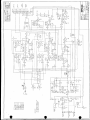
RM-120A Schematics.
1
2
3
4
7
8
2
3
3
4
9
NOTrcr:
of the
While Clear-Con makes every attempt to maintain the accuracy
is subject
information contained in its product manualS. the information
change without notice:
DOCUMENTATION ADDENDUM
RM-120A
4*
*
MANUAL
REV.A
17, 1987
*4
at
sNovember
44
*
4* *it
* 4 4*
4*
4tW*44
4
*t
*J
* 4
41.4$sst 14
*J ****$**i*
4
* .
44X
4
* *
$*s**
MIC TO LINE GAIN LEVEL INCREASE
In effecting a 4dB Mic to Line increase in gain level, the
following changes have been made:
Change:
At:
100K OHM
R50,
1.5K OHM
R2 3
To:
R51
220K OHM
2.77K OHM
I.
INTRODUCTION TO THE RM-120A SPEAKER STATION
The RM-120A is a remote speaker
station that allows selectable communicating in the Clear-Com System.
The operator can talk and listen on
Channel A, Channel B, or both at
once (without tying them together).
The RM-120A mounts in a 19" rack,
using just 1.75" vertical space.
It features a wide frequency response speaker and operates with a
carbon headset or a dynamic headset/telephone-style handset.
The rear panel provides a 1/4" jack
for output to an external speaker
(using it disconnects the internal
speaker). The operator can turn
down the volume of the built-in or
external speaker to have a private
conversation with a headset. Alternately, the gooseneck or headset
mic can be turned off to use the
RM-120A for "listen-only" (paging).
The RM-120A provides a balanced
program input for monitoring external audio in the speaker or headset.
The
RM-120A mixes the program with the intercom signal for
monitoring in the headset and/or
speaker. The station provides separate controls for adjusting intercom and program volume levels.
The "Stage Announce" feature is for
paging applications. The RM-120A
provides a balanced,
line-level
output signal to a 1/4" phone jack
(on the rear panel).
The Stage
Announce button on the front panel
activates this output, giving the
operator access to an
external
speaker/amp system. Pressing Stage
Announce mutes the operator's voice
to the intercom channels.
Visual Signalling is a standard
Clear-Com feature. The "Call" button attracts the attention of intercom users who have removed their
headsets or turned off their speakers (it can also activate remote
control of KB-112 Stations). The
RM-120A provides a Call button to
signal stations on the channel(s)
chosen with the "Channel Select"
toggle switch.
Each channel has a
lamp to indicate incoming signals,
regardless of the Channel Select
switch position.
The RM-120A sidetone control allows
the operator to adjust the level of
his/her own voice as heard in the
station's headset/speaker.
Sidetone control helps to prevent acoustic feedback when using the speaker and gooseneck mic simultaneously.
You need only adjust sidetone
when you set up the system (if at
all), not when other stations join
or leave the intercom system.
The
RM-120A
provides excellent
speech intelligibility in all surroundings.
It features "Automatic
Headset Detection," which shuts off
the mic preamp when a headset is
not plugged in.
This prevents
noise pick-up on the intercom line
from the unused connector. The RM120A also incorporates a mic limiter, which assures constant talk
levels and prevents overload.
Gooseneck Mic Option
The RM-120A is available with a
noise-cancelling electret mic on a
flexible gooseneck. Though permanently attached, the length of the
gooseneck is field-adjustable. The
electret element has unusually high
immunity to ambient room noise and
speaker feedback, thus permitting
practical "hands-free" operation.
You activate the mic by setting the
Mic On/Off/(On) switch to "(On)"
(momentary on), which attenuates
the speaker by 6 dB to reduce the
possibility of feedback.
The RM-120A provides two 3-pin, XLR
connectors
for each channel (4
total; two inputs, two extensions).
Standard two-conductor,
shielded
mic cable connects the RM-120A to
the intercom system.
II. HEADSETS AND MICS
To assure proper level and performance, the dynamic headset should
have the following characteristics:
150-250 ohms
mic Impedance:
-55 dBv
Nominal Output Level:
dynamic
Headphone Type:
300-2000 ohms
Impedance:
The RM-120A provides:
--one 1/4" phone jack for a standard carbon headset, AND
--one 4-pin, male, XLR connector
for dynamic headset, telephone
handset, or push-to-talk mic.
The RM-120A's built-in headset amplifier can drive a headset to levels greater than 110 dB SPL, and
drives two dynamic headsets with
only a 3 dB reduction in level when
connected with the proper "Y" cord.
NOTE: If you simultaneously use a
carbon headset and a dynamic headset, the level in the carbon headset drops audibly.
Carbon headset connections:
Ring-----Headphone
Tip------Mic
Sleeve---Ground
It's easy to make an extension cord
For the
for your dynamic headset.
cable, we recommend Belden 8416 or
the equivalent (2-conductor, 25gauge) or Belden 8734 or the equi22-gauge).
(3-conductor,
valent
See the diagram below. The cord
length should be 15 feet or less;
anything longer might lead to capamic sigcitive coupling between
nal and headset signal, causing
oscillation or a loss in frequency
response.
To assure proper level and performance, the carbon headset's mic
impedance should be 50 ohms, and
earphone impedance should be 3002000 ohms.
Dynamic headset connections:
Pin 1----Mic Ground
Pin 2----Mic Hot
Pin 3----Headphone Ground
Pin 4----Headphone Hot
Caution: Do not connect mic ground and headphone ground together.
Figure 1: Headset Extension Cord
15
OR
LESS
NoTe Heaosel eaos o0noi nave
to Deshiecea on BelDen 8734
51A4FLDEDPAIR
BELDEN 8416
PIN 1: MIC GROUND
PIN 2: MIC HOT
PIN : HEADPHONE GROUND
Pin 4: HEADPHONE HOT
2
CAUTION: DO NOT CONNECT
MIC GROUND & HEADPHONE
GROUND TOGETHER
4
III. RN-120A INSTALLATION
0
The RM-120A connects to the intercom system via two pairs of 3-pin, XLR
connectors on the rear panel.
1) Route each channel on a separate, two-conductor, shielded mic cable
(e.g. Belden 8413) from the Main Station intercom output connectors to
the rack location of the RM-120A.
2) Rack-mount the RM-120A and then apply the intercom inputs to the appropriately labelled (Channel A or Channel B) 3-pin female connectors (on
the rear panel).
The 3-pin male connectors provide a hard-wired loop-through for each
channel, which allows extension ("daisy-chaining") of the intercom
lines to other stations in the system.
The pin assignments for all intercom connectors are:
Pin 1: Common
Pin 2: +30 VDC
Pin 3: Intercom Audio
Ch. A or B
S7vl3
t
A
t
g1
CHASSIS OEPTH
6.62'
eor(Om.
t
3) Program Input: the RM-120A rear panel contains a 3-pin female connector for input of a balanced, line-level auxiliary input. Pin 1 is
ground, and Pins 2 and 3 are hot.
The program input is transformer-coupled; it will also accept an unbalanced input if you ground either of the hot leads. A 0 dB signal
will drive the headset/speaker to full output. The impedance of the
program input is l0k ohms bridging.
The program audio mixes with the intercom audio (in the station's
headset and speaker outputs only), and the listen-levels of each are
adjustable via the RM-120A front panel controls.
4)
Stage Announce connection from rear panel: output to speaker/amp paging
system (600 ohms impedance); ring/tip/sleeve connections.
RM-120A
ii ORB
CH. A
CH, B>IIIPT
&
|
RM-120A
I|
I Lig
I
RM-120A
ARB QE3 |
XESO
INTERCOM OUTPUT
FROM MAIN STATION
STANDARD 2-COND.
SHIELDED MIC CABLE
DAISY-CHAIN
INTERCONNECTION
3
IV. Rm-120A OPERATING CONTROLS & CONNECTORS
The RM-120A controls and connectors are described below in the order in
which they appear on the FRONT PANEL from LEFT to RIGHT.
Fo
r
© ¾
~~~~~~~~~~RM.120A
=©
0 000-°
1,
;44' 2i
==
-f]H
O
Jp
1900
-48260)
Call
The Call
com user
headsets
trol the
push-button activates visual signalling. It allows the interto attract the attention of operators who've removed their
or turned off their speakers. The Call button can also conspeaker or mic at KB-112 Stations set up for remote control.
The Call signal follows the position of the "Channel Select" switch; if
you using Channel A, the Call button causes the lamps to light at all
other stations using Channel A (and likewise for Channel B). When the
Channel Select switch is set to "both," the lamps at all stations on
both channels shine simultaneously. The Call signal is active for as
long as you keep your finger on the Call button.
Receiving Signals: The amber Call lamp on the left, for Channel A,
lights when any station on that channel activates the Call circuit.
The amber Call lamp on the right, for Channel B, lights up when any
Channel B station activates Call. They operate independently of the
setting of the Channel Select switch.
Note: an internal jumper reverses the Call function for use with
KB-112 remote control-- call Clear-Com for info.
Channel Select
This 3-position toggle switch assigns the RM-120A speaker/headset monitoring function to (1) Channel A, (2) Channel B, or (3) both channels
(RM-120A operator can talk/listen to stations on Channel A and stations
on Channel B, but Channel A stations cannot talk/listen to Channel B
stations-- unless a Party Line system has been set up via the Main
Station).
Sidetone Adi
The sidetone adjustment, which is controlled with the blade of a small
screwdriver, allows the RM-120A operator to add back a fixed level of
his/her voice in the speaker or headset, regardless of which channels
are selected. When using the gooseneck and speaker simultaneously,
this control should be turned all the way down to further reduce the
possibility of feedback.
Internal Trimpots (schematic reference, P5 and P6): One sidetone null
control per channel; you need only adjust the sidetone once at the time
of installation (if at all), even if other stations subsequently join
or leave the intercom system. Adjusting the sidetone does not affect
the level of incoming or outgoing signals.
(continued)
4
At the factory, Clear-Com sets the internal sidetone null to the best
overall null with 500 feet of cable. If the sidetone is not nulled
enough, feedback may occur between the speaker and the mic. To adjust
the internal sidetone null:
1)
2)
3)
4)
remove top cover of unit
plug in headset and turn on mic (or activate gooseneck mic)
turn up Headset Volume
talk into mic while slowly turning sidetone adjustment clockwise.
Find the null point where you can barely hear yourself. This is the
proper setting for minimum feedback when using both the speaker and
a mic. Adjust individually for each channel.
Program Volume
Speaker Volume
Headset Volume
These knobs adjust listen-levels of the auxiliary program and overall
intercom activity, as heard in the speaker and headphones.
Stage Announce
This push-button activates the feature designed for paging applications. The RM-120A provides a balanced, line-level output signal to
a 1/4" phone jack on its rear panel. The Stage Announce button activates this output, giving the operator access (via headset or gooseneck
mic) to the external speaker/amp system. Pressing Stage Announce also
mutes the operator's voice to the intercom channels.
Vic On/Off/(On)
This 3-position toggle switch turns the mic on or off in your carbon)
and dynamic headse or the gooseneck iic.
With-the-switch set to the
top "on" position, the mic stays on. When in the middle position, the
mic is off. The bottom position "(on)" is a momentary setting.
PROGRAM INPUT
3-pin female XLR connector; pin-out assignment is:
Pin 1--ground
Pin 2--input
Pin 3--input
The auxiliary program input is on the RM-120A rear panel. It accepts a
balanced, line-level input (input impedance is 10k ohms bridging; a
0 dBv nominal signal drives the headset to full output). The RM-120A
operator can monitor program along with intercom activity in the headset/speaker. A split-feed option, set up at the Clear-Com factory,
separates the intercom and program signals for use with a binaural (6pin, stereo) dynamic headset.
STAGE ANNOUNCE OUTPUT
1/4" phone jack; 3-circuit (ring/tip/sleeve); 600 ohms output impedance.
EXTERNAL SPEAKER OUTPUT
1/4" phone jack; 2-circuit (internally-switched; ring/tip); disconnects internal speaker; output for speaker with impedance of 8 ohms or
more (preferably 16 ohms).
5
V. RN-120A SPECIFICATIONS
AMPLIFIER DESIGN
Solid-state, integrated circuit amplifiers which include a mic pre-amp
with limiter, headset power amp, speaker power amp, and signalling
circuitry. Current-limited with short-circuit and reverse polarity
protection.
MIC PRE-AMPLIFIER
250-12k Hz, with
Freq. Response:
mic limiter; contoured
to enhance intelligibility
lk ohms
Mic Input Impedance:
+37 dB
Mic Preamp Gain:
Max Input Before Clipping: -10 dBv*
25 dB
Mic Limiter Range:
HEADSET/SPEAKER AMPLIFIER
100-18k Hz, 12 dB
Freq. Response:
Load Impedance Range: 300-2000 ohms
(dynamic headset)
+18 dBm, 26v p-p
Output Level:
@ 200 ohms
+110 dB SPL
Headset Level:
(with standard Clear-Com headset)
Headset Distortion: 0.2% THD @ lkHz
+37 dB
Headphone Amp Gain:
Speaker-Type: 16 ohm, 3"x 1.5" oval
Spkr. Amp Output: 2.5w into 16 ohms
Speaker Level: +98 dB SPL @ 3 feet
GENERAL SPECS
OdBv max, -18dBv nom.
Line Level:
Sidetone Adj: 35 dB null to full on
Signal Voltage: l1VDC on audio line
4 volts
Call Light Sensitivity:
68 dB
Signal-to-Noise:
-118 dB
Equivalent Input Noise:
Station Bridging
>12k ohm (200-10k Hz)
Impedance:
Power Requirements: 25 mA quiescent
100 mA signal, 100 mA avg. talk
200 mA short-circuit
Voltage Range: 12-32V, 28V nominal
Dimensions: 1.75" x 19" x 6.5" deep
44 mm x 483 mm x 165 mm
CONNECTORS
4-pin XLR, male
Dynamic Headset:
1/4" phone jack
Carbon Headset:
(4) 3-pin XLR
Line:
Channel A--i male, 1 female
Channel B--i male, 1 female
3-pin XLR, female
Program Input:
1/4" phone jack
Ext. Speaker:
(disconnects internal speaker)
* 0 dBv is referenced to 0.775 volts EMS
7
VI. RK-120A PARTS LISTING
Part #
210002
210003
210013
210050
210055
240015
240017
250128
250224
250073
250152
250163
390013
500095
510012
640028
710054
710158
810031
8
Description
Conn, intercom/prgm, D3F
Conn, intercom, D3M
Conn., headset, D4M
Conn., 1/4" phone jack
Conn., 1/4" jack w/switch
Knob, black, 1/2"
Handle, chrome
RM+-120A rear panel
RM-120A front panel
Chassis mainframe, 1.75"
Chassis top cover
Speaker screen
Lamp lens, amber
(390012 Bulb, 28v)
Speaker, 16 ohm, oval
Switch, momentary pushbutton
Hole plug, 3/4"
Gooseneck Mic
RM-120A electronics assy.
RM-120A instruction manual
Qty.
3
2
1
2
1
3
2
1
1
1
1
1
2
Schematic Reference ID
J1, stage announce
ext. speaker
P1, P2, P3
L1, L2
1
H5 (call)
2
1 (without gooseneck)
1 (optional)
1
I
~~~~~~~~~ ~ ~ ~ ~ ~ ~ ~ ~ ~ ~ ~ ~ ~ ~ ~ ~ ~ ~ ~ ~ ~ ~ ~~~~~~~-I
a Z
t
L
cm
Li
4
-nI
''0,-
(k
~
~
~
~
~
~
S
-I
4
0~~~~~~~~~~~~~~~~~~~~~~~~~~~~~
(07
-.
~
~
~
~
~~~~~~~~~~~2
0~~j
OF-~~~~~~~~~~~~
'J
0
10~~~~~~~~~~~~~~~~~~~1_____________________
CI~~~~~~~
2
r-~t
r>K
m~
r-~m
_____
A
[00
0
(1~~~~~~~~~~~~~~~~~~~~~~~~~~~~~~~~~~~~~~~~~~q10
0
J
0
U4-~,01
a
Ii~~~~~~~~~~
.JI'A0
Q
Z~~~~~~~~~~~~~~~~N
S
,~~~ '~
diNU
CL
_________
am
~~~~~•
JSI
______
N
2
2
CC
-
~~~~dovlI-
4
<
'
C~~~~~~~~~~~flh;H4
-L1
A
1
I
,1
'~~I
2
<-jit
41
I
-~~~~~~~~~~
-
/+HI
'A
01
o
o
0~~~~~~~~~~~~~~~~~~~~~~~~~~~Mjol
01
'A
OU
I~~~
-~~~~~~~m2 'Ne
-
-C
-
LV~~~~~~~~~L
IS~~~~~~~~~~~~~~~~~~~~
~~~~~IL
-:
,II
too
u
Lg~~~~n
S 'V
Z
>10;
7g
A0
0
C
~~~~~~~~iI
I
I'
UUI
~~
L~J
u~~~~~~~~~0??
A2
21?;~~~~~~~~~~~~~~
5
"
2
k
:
ffi
z
1tl
Ez
s
F
2<
~ ~~~~
Ln
~
~
fi
~
~
~
~
~
£~
h~~~~~~~~
nZF
~ ~ ~ ~ ~
n
. c
JJ
Ln
r
C
;
;0Qj
,it~~~~~~~~~~l,,t~~
L
}
>
ur tf
LI~~~~~~~~~~~~~~~~~~~~~~~~~~~~~~L
a X I
1
M
3~~~~~~~~~~
t~~~~~~~