1
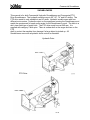
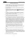
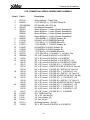
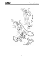
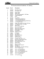
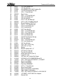
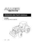
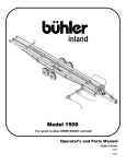
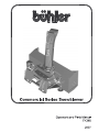
Commercial Snowblower
TABLE OF CONTENTS
DESCRIPTION
PAGE
Warranty ...................................................................... 1
Safety Instructions ....................................................... 2
Safety Signs & Safety Sign Locations.......................... 3
Operating Instructions.................................................. 5
Hydraulic Control Block Instructions ............................ 7
Hydraulic Control Block Parts List & Drawing .............. 8
Assembly Instructions .................................................. 9
Hydraulic Snowblower – 22” Housing Drawings .......... 12
Hydraulic Snowblower – 22” Housing Parts List .......... 14
Hydraulic Snowblower – 24” Housing Drawings .......... 17
Hydraulic Snowblower – 24” Housing Parts List .......... 19
Hydraulic Snowblower – Assembly Drawing................ 21
Hydraulic Snowblower – Assembly Parts List .............. 22
PTO Snowblower – 24” Housing Drawings.................. 23
PTO Snowblower – 24” Housing Parts List.................. 25
PTO Drawing & Parts List ............................................ 27
Cylinder Assembly Drawing & Parts List...................... 28
Gearbox Drawing & Parts List...................................... 29
Specifications............................................................... 30
Hydraulic Snowblower Schematic................................ 31
Troubleshooting ........................................................... 32
Shipping Bundles ......................................................... 33
Commercial Snowblower
WARRANTY POLICY
Buhler Manufacturing products are warranted for a period of twelve (12) months (90 days for
commercial application) from original date of purchase, by original purchaser, to be free from
defects in material and workmanship under correct, normal agricultural use and proper
applications.
Buhler Manufacturing’s obligations under this warranty shall be limited to the repair or
exchange, at Buhler Manufacturing’s option, of any Buhler Manufacturing product or part which
proves to be defective as provided. Buhler Manufacturing reserves the right to either inspect
the product at the buyer’s location or have it returned to the factory for inspection.
The above warranty does not extend to goods damaged or subject to accident, abuse or misuse
after shipment from Buhler Manufacturing’s factory, nor to goods altered or repaired by anyone
other than an authorized Buhler Manufacturing representative.
Buhler Manufacturing makes no Express Warranties other than those, which are specifically
described. Any description of goods, including any references and specifications in catalogues,
circulars and other written material published, is for the sole purpose of identifying goods and
shall conform to such descriptions. Any sample or model is for illustrative purposes only and
does not create an Express Warranty that the goods conform to sample or model shown.
The purchaser is solely responsible for determining suitability of goods sold. This warranty is
expressly in lieu of all other warranties expressed or implied. Buhler Manufacturing will in no
event be liable for any incidental or consequential damages whatsoever. Nor for any sum in
excess of the price received for the goods for which liability is claimed.
WARRANTY CLAIMS:
Warranty requests must be prepared on Buhler Manufacturing Warranty Claim Forms with all
requested information properly completed. Warranty Claims must be submitted within a thirty
(30) day period from date of failure repair.
WARRANTY LABOR:
Any labor subject to warranty must be authorized by Buhler Manufacturing. The labor rate for
replacing defective parts, where applicable, will be credited at 100% of the dealer’s posted shop
rate. Defective parts will receive an extra 10% discount to assist with freight or other incidental
costs.
GOVERNMENT LEGISLATION:
Warranty terms and conditions are subject to Provincial or State legislation.
IMPORTANT FACTS:
Buckets and Bucket Tines Carry No Warranty
Bent Spears Carry No Warranty
Snowblower Fan Shafts Carry No Warranty
Mower Blades Carry No Warranty
Portable Auger Parts Have Two (2) Year Warranty
Loader Parts Have Two (2) Year Warranty
IMPORTANT NOTE: This warranty does not apply to rentals
1
Commercial Snowblower
SAFETY INSTRUCTIONS
CAUTION
1.
Always review operator’s manual before starting new machine.
2.
Do not let inexperienced operators or children run this equipment.
3.
Never service or clean unit while it is running.
4.
Do not remove shields.
5.
Stay clear of augers.
6.
Stay clear of discharge chute. Rocks can be picked up and thrown.
7.
Do not operate in the fully raised position.
8.
Relieve pressure on hydraulic system before repairing or adjusting.
9.
Wear hand and eye protection when looking for hydraulic leaks. Use
cardboard to look for leaks.
10.
The quick tach must be securely locked in place before using snowblower.
11.
Poor judgment results in accidents. Always be careful.
12.
Remember a careful operator is the best insurance.
THIS SYMBOL MEANS
STAY ALERT! WATCH FOR IT!
2
Commercial Snowblower
SNOWBLOWERS
This manual is for both Commercial Hydraulic Snowblowers and Commercial PTO
Drive Snowblowers. The hydraulic models come in 60”, 66”, 74” and 84” widths. The
PTO drive model is only available in an 84” width. Hydraulic models come with four
different motor series. Hydraulic output on the equipment running the Snowblower must
match the requirement for each motor series for the Snowblower to work. The hitch is a
skid steer fixed type of quick hitch. The PTO drive model runs at 540 rpm. It is
supplied with category 2 hitch pins. There is a shear bolt on the auger and two on the
PTO
shaft to protect the machine from damage if a large object is picked up. All
Snowblowers come with a hydraulic chute control as standard.
Hydraulic Drive
PTO Drive
3
Commercial Snowblower
SAFETY SIGNS
#1
#3
#3
Replace safety signs
immediately should they
become damaged, torn or
illegible. Obtain replacements
from your authorized dealer
using the part numbers shown.
#4
4
Commercial Snowblower
OPERATING INSTRUCTIONS
1. HYDRAULIC DRIVE: All snowblower hydraulic blocks are set at the factory
for a 2800 - 3000 psi system. Refer to the section on the hydraulic control
block if your system does not fall into this range.
2. ALL: Depth of the cut can be partially controlled by tilting the snowblower
forward or backward.
3. PTO DRIVE: Adjust the top link of the tractor hitch so the snowblower is just
slightly tilted back when resting on the ground.
CAUTION: Excessive
backward tilt may cause the “U” joints to flutter resulting in PTO shear bolt
failure.
4. PTO DRIVE: The inside holes on the hitch are spaced to fit a category 2
quick hitch using the pins supplied. The hitch will also fit category 2 three
point arms or category 3 if you add bushings.
5. PTO DRIVE: Adjust the lower link sway chains or blocks on the tractor to
restrict movement of the blower when operating.
6. ALL: All snowblowers have a hydraulic control spout and spout deflector.
Refer to the hydraulic control block section. The pressure to the chute control
is regulated by the two torque limit controls (#13b and #13c). Each controls
the hydraulic pressure in one direction. They are set at the factory to about
2 ½ turns. If the pressure is too low, the chute won’t turn. If the pressure is
too high you could damage the teeth on the spout control ring. To adjust the
pressure, you loosen the lock nut on the modulating valve and back off the
adjusting screw till the screw turns freely by hand. Turn the screw in till you
feel it making contact and turn in 2 ½ turns. Start with this setting to do any
fine adjustment if necessary. Pressure should not go over 1000 psi.
The deflector cylinder pressure is regulated by no-load control (#13a).
It is set at the factory to about 2 turns. If pressure is too low it will not
operate. Excess heat will be generated if it is set too high. Adjust if
necessary as per previous paragraph. Operating pressure should be about
700 psi.
7. ALL: Run the snowblower at low rpm to check operation before blowing
snow.
8. PTO DRIVE: The blower has three shear bolts to protect the tractor and
blower in case a large object enters the blower. PTO shear bolt – two 5/16” x
1” (grade 8); auger shear bolt – 5/16” x 1 ¼” (grade 5). Shear bolts should be
fastened with a lock nut or two jam nuts. These bolts must be tight to prevent
wear of the bolts and bolt holes.
9. PTO DRIVE: Never run PTO at over 600 rpm.
5
Commercial Snowblower
OPERATING INSTRUCTIONS – cont’d.
10. ALL: Chain tension on auger chain should be set at 3/8” to 1/2” slack.
11. LUBRICATION:
a) ALL: The gear teeth on the chute control should be periodically
lubricated with gun grease.
b) PTO DRIVE: PTO shaft universal joints and square shaft slide should
be periodically lubricated with a grease gun.
c) ALL: Regularly oiling the chain will significantly increase the life of the
chain.
d) PTO DRIVE: Use any 80-90 gear oil or multigrade with 80 minimum in
the gearbox up to the level plug height.
12. ALL: Periodically check all bolts for tightness. The bolt holding on the fan
and the bearing bolts are of particular importance.
13. HYDRAULIC DRIVE: Always use goggles and gloves when checking for
hydraulic leaks. Use a piece of cardboard instead of your hands to look for
leaks.
14. ALL:
Always shut off snowblower for servicing or unplugging. Disengage
hydraulics or PTO shaft.
15. PTO DRIVE: Check the shear sprocket at the beginning of every season to
make sure it will spin freely. Clean to loosen if necessary.
16. ALL: When replacing bearings or tightening a loose bearing collar, always
tighten collar in the direction of shaft rotation using a center punch or a similar
tool.
17. HYDRAULIC DRIVE:
WARNING: The locking pins must extend through
the holes in the attachment when mounting the snowblower to an implement.
Levers must be fully down and locked. Failure to secure pins can allow
attachment to come off and cause injury or death.
6
Commercial Snowblower
HYDRAULIC CONTROL BLOCK
NON-STALLING-FAN FEATURE:
The Hydraulic Snowblower has a unique modulating element that keeps the blower fan
from stalling in an overloaded condition. This is accomplished by starving the hydraulic
flow to the front auger motor (which then stops feeding the fan) and diverts all of the
flow (and energy) to the main fan motor. As the fan clears itself, and the pressure
drops, the auger again begins feeding according to load. When the system is set up
properly the fan motor should not stall or plug up.
MODULATING ELEMENT SETUP:
For optimum performance the modulating element (#4) (page 8) must be adjusted to
match the system pressure of the tractor being used. The factory setting is for a 28003000 psi system. If your system is less, you should make adjustments accordingly. For
adjustment:
Loosen the LOCK NUT (on the MODULATING VALVE (#4) (page 8) and back off
the adjusting screw till the screw turns freely by hand, and then turn it in till you
feel the screw making contact with the pressure spring. One turn sets the
pressure up by about 600 psi.
For 2100 psi turn the screw in 3 ½ turns.
For 2400 psi, turn in 4 turns
For 2700 psi, turn in 4 ½ turns
For 3000 psi, turn in 5 turns.
If the fan stalls (in an over load condition), the (#4) (page 8) element is set too high. If
the Auger slows and stops too soon, it is set too low. Once it is set it should not need to
be adjusted any more.
Since there are a number of unknown variables that are unique to almost every
situation, it is difficult to give an exact setting for a particular model. The variables are:
hose size and length, type and size of quick couplers, etc.
7
Commercial Snowblower
HYDRAULIC CONTROL BLOCK DRAWING AND PARTS LIST
HYD MANIFOLD ASSEMBLY
Item #
Part #
Description
1
2
3
4
5
6
7
8ab
9
10a
10bc
10ef
11
12
13a
13bc
14
15
16
905669
813922
X2732
813923
X2733
813924
X2734
813925
X2735
813926
813926
813926
813929
X2736
813930
813930
X2737
813931
X2745
Main Block
Logic Element
Element Seal Kit
Control Valve
Seal Kit
No-Load Valve
Seal Kit
Chute Cont. Valves
Seal Kit
No-Load Press. Coil
Chute Up Down Coil
Chute Left Right Coil
Check Valve
Seal Kit
No-Load Control
Torque Limit Control
Seal Kit
Check Valve
Seal Kit
8
Commercial Snowblower
ASSEMBLY INSTRUCTIONS
1.
SPOUT ASSEMBLY FOR ALL SNOWBLOWERS: Remove two of the
grooved spout rollers to mount the discharge spout. Replace the two rollers
to hold spout in place. Install the 2 ½” x 8” cylinder on the spout using the
pins supplied.
2.
HYDRAULIC DRIVE: (Page 21 & 22) The 80” long hydraulic lines (#14) for
the spout deflector cylinder should be connected to the two ports on the
hydraulic block labeled C1 and C2 (see Page 8 for block drawing). The 30”
long lines (#15) from the spout control motor connect to the two ports labeled
M1 and M2 on the hydraulic block. The ¾” diam. x 84” main
lines (#21) connect to the implement. NOTE: The customer must supply the
appropriate tips to connect the main lines to the implement. A two-piece
wiring harness is supplied with all hydraulic snowblowers. The 45” part of the
harness (#6) is mounted on the snowblower. One end of this wire connects
to the control block. The plug end mounts on a bracket welded to the top
edge of the quick hitch. The 155” part (#1) of the harness with the switch is
connected to the plug on the harness mounted on the snowblower. A switch
mounted in the cab controls the spout and the deflector. The alligator clips
attach to the battery which acts as a power source. A schematic of the wiring
harness is included in this manual. (See page 31)
3.
PTO DRIVE: (Page 23-26)
1. Slide the two hitch adaptor weldments (#17) into the sleeves on the body.
These tubes are adjustable to three different positions. The correct position
for each individual tractor will be determined when mounting the snowblower
on the tractor (see section on mounting blower on tractor). Start with the
tubes pulled out to the last hole. Connect to the snowblower using pins (#71)
and linch pins (#73).
Mount the hitch Weldment (#7) to the body. The top arm of the hitch bolts on
top of the bracket on the body using a ¾” x 1 5/8” bolt, lock washer and hex
nut. The bottom of the hitch bolts to the outside of the two hitch adaptors
using 5/8” x 1 ¾” hex bolts, flat washers, lock washers and hex nuts.
2. Connect two 108” hoses (#76) to the hydraulic spout control motor and
two 108” hoses (#76) to the cylinder on the discharge spout. Connect these
hoses to the tractor after mounting the snowblower on the tractor.
3. Mounting blower on tractor:
a)
The pins supplied with the snowblower are for a category 2 quick
hitch. The quick coupling hitch has two holes both at the top of the
hitch and at each lift arm. When using a quick coupler, the pins
must be in the inside set of holes. Use the outside set of holes
with a standard three-point hitch.
9
Commercial Snowblower
ASSEMBLY INSTRUCTIONS – cont’d.
b)
Using tape or a bright colored marking pen, mark on the outer
shields the position where the shaft is completely pushed together
and the position where you have a 4” overlap. Watch these marks
when moving the blower through all possible operating angles to
see that the PTO shaft stays within this range.
c)
With the engine on the tractor shut off, attach the PTO shaft. The
tractor end has a standard 6-spline end with a spring loaded locking
collar. The snowblower end has a clamp-style yoke with a 3/8” key
way. Slide the yoke onto the gearbox shaft with the 3/8” key (#67)
supplied. Lock the yoke in place with the ½” x 3” bolt (#39) and
lock nut (#40) fitted through the groove in the gearbox shaft. After
tightening the bolt, insert and tighten the 3/8” socket set screw
(#74) supplied.
Caution: Always check to see that both ends of the PTO shaft are securely
attached every time the Snowblower is used. This should always
be done with the tractor engine off.
d)
e)
Check that the PTO shaft does not bottom or separate with the
blower in the extreme high and low positions. A longer optional
PTO shaft is available if the standard shaft is too short. Check for
free movement of all parts in various raised positions; particularly
the PTO shaft.
NOTE: Excessive U-joint wear and shear pin failure may result if
the tractor PTO angle exceeds 20º. The drawing below gives an
approximate way to check this angle. With the PTO half extended,
the tractor output should not be over 32 inches high. Use 34 inches
if the PTO is nearly compressed.
10
Commercial Snowblower
ASSEMBLY INSTRUCTIONS – cont’d.
4. PTO SHIELD: All PTO snowblowers are supplied with a PTO shield
(#18). To install, remove the two rear bolts at the top of the gearbox
(#34). Bolt the PTO shield to the gearbox by the hinges using these same
bolts. A utility spring (#68) keeps the shield in place. Hook one end of the
spring in the hole in the shield and the other end to the hole in the brace
under the gearbox.
CAUTION:
Do not run the snowblower without this shield in place.
REFILLING GEARBOX WITH OIL: If the gearbox requires refilling with oil
because of repairs to the gearbox, add oil to the level shown in drawing.
Check the level regularly using the plug in the lid. The correct level is
even with the bottom of the plug.
11
Commercial Snowblower
HYDRAULIC COMMERCIAL SERIES SNOWBLOWER – 22” HOUSING
12
Commercial Snowblower
13
Commercial Snowblower
WHEN ORDERING PARTS
Always give your dealer the Model, Color and Serial Number of your machine to assist
him in ordering and obtaining the correct parts. Use the exploded view and tabular
listing of the area of interest to exactly identify the required part.
Hyd Commercial Series Snowblower - 22'' Housing
Item # Part #
1
2
3
4
5
6
7
8
9
10
11
12
13
14
15
16
17
18
19
20
21
905536
909590
905534
905226
905206
909606
905210
905550
965912
909608
902880
909592
902883
905291
906658
965426
965430
906322
906323
906332
905623
905694
905695
905624
906335
967440
905241
968627
967260
902869
905289
905362
905299
905528
906311
Description
Main Body Weldt - 74''
Main Body Weldt - 66''
Main Body Weldt - 60''
Fan Weldt - 22''
Auger Weldt - 74''
Auger Weldt - 66''
Auger Weldt - 60''
Spout Weldt
40 Tooth Sprocket #60, 1 3/8'' Bore
48 Tooth Sprocket #60, 1 3/8'' Bore - 66"
Cutting Edge (74'')
Cutting Edge (66'')
Cutting Edge (60'')
Adaptor
Roller Chain (#60H x 72 Links w/ Conn)
Roller Chain (#60H x 75 Links w/ Conn) - 66"
1 3/8'' Housing W/ Bearing
1 3/8'' Bearing W/ SS Lock
Auger Sprocket 15T #60 (1 1/4'' Bore) (Ser 1 - 3)
Auger Sprocket 15T #60 (1 1/2'' Bore) (Ser 4)
Spout Liner
Fan Motor - 2 Hole (Ser 1)
Fan Motor - 2 Hole (Ser 2)
Fan Motor - 2 Hole (Ser 3)
Fan Motor - 4 Hole (Ser 4)
Spout Motor
Pop Rivet SD68BSLF
Spout Gear Weldt
1 1/2'' Bearing w/ Collar
1 1/2'' Bearing Flange (Set)
Fan Motor Mount Plate (Ser 1-3)
Fan Motor Mount Plate (Ser 4)
Roller Chain (#80H x 30 Links w/ Conn)
Auger Motor Mount Plate (Ser 1-3)
Auger Motor Mount Plate (Ser 4)
Hyd Box Shield Weldt
14
Commercial Snowblower
22
23
24
25
26
27
28
29
30
31
32
33
34
35
36
37
38
39
40
41
42
43
44
45
46
47
48
49
50
51
52
53
54
55
56
57
58
59
60
905224
22695
909593
902407
909594
909610
103753
12779
960719
905309
960719
909430
905181
24981
905554
906660
81620
84277
906655
87553
811791
81624
81624
812364
81638
81637
81636
86170
86171
811792
967431
81593
812363
81592
905543
905648
905647
81568
906393
81569
81549
988999
902874
84268
Fan Shaft 1 1/2'' x 15 1/4''
Chain Cover
Chain Cover - 66"
Skid Plate Weldt
Skid Plate Weldt Lh - 66"
Skid Plate Weldt Rh - 66"
Cylinder Clevis Pin 1'' x 4''
Hair Pin Clip #9 Western Wire
Sprocket 15T, #80, 1 1/2'' Bore
Sprocket 15T, #80, 1 1/4'' Bore (Ser 1-3)
Sprocket 15T, #80, 1 1/2'' Bore (Ser 4)
Spout Roller
Spout Link 22''
Cylinder 2 1/2'' Dia x 8''
Spout Sprocket Cover
1/2'' x 2'' Sq Hd Set Screw (pl)
1/2'' x 1 1/4'' Hex Bolt (pl)
1/2'' x 1 1/2'' Hex Bolt (pl)
1/2'' x 1 1/2'' Fl Hd Bolt (skt) (pl)
1/2'' x 1 3/4'' Hex Bolt (pl)
1/2'' x 2'' Hex Bolt (pl) (Series #1-3)
1/2'' x 2 1/4'' Hex Bolt (pl) (Series #4)
1/2'' x 2 1/4'' Hex Bolt (pl)
1/2'' Lock Nut (pl)
1/2'' BS Flat Washer Std (pl)
1/2'' Lock Washer (pl)
1/2'' Hex Nut (pl)
3/8'' x 1'' Hex Bolt (pl)
3/8'' x 1 1/4'' Hex Bolt (pl)
3/8'' x 1 1/2'' Hex Bolt (pl)
3/8'' x 1'' Flat Bolt (skt) (pl)
3/8'' Lock Washer (pl)
3/8'' Lock Nut (pl)
3/8'' Hex Nut (pl)
3/8'' x 4'' Auger Chain Bolt Weldt
Spout Liner Middle
Spout Liner Bottom
5/16'' Hex Nut (pl)
5/16'' x 3/4'' Fl Hd Bolt (skt) (pl)
5/16'' Lock Washer (pl)
5/16'' x 3/4'' Hex Bolt (pl)
3/8'' x 3/8'' Socket Set Screw
Spout Motor Mount Plate
5/8'' x 1 1/2'' Hex Bolt (pl)
15
Commercial Snowblower
61
62
63
64
65
66
67
68
69
70
71
72
73
74
75
81677
81678
965821
905310
900712
961012
905278
905336
906348
906574
812026
907590
908966
907689
909277
5/8'' Lock Washer (pl)
5/8'' BS Flat Washer Std (pl)
3/8'' x 1 3/4'' Key
3/8'' x 4 1/2'' Key
Skid Pin Weldt 5/8'' x 3''
#16 Hair Pin Clip (pl)
Cover Plate
Fan Housing Liner 68''
Motor Washer 13/32'' hole x 2'' OD
Bronze Bushing 7/8'' OD x 1''
5/16'' x 1'' Hex Bolt (pl)
Spout Hose Holder
Spout Liner Bottom (truckloader)
Spout Weldt (truckloader)
Manual Hldr
16
Commercial Snowblower
HYDRAULIC COMMERCIAL SERIES SNOWBLOWER – 24” HOUSING
17
Commercial Snowblower
18
Commercial Snowblower
Hyd Commercial Series Snowblower - 24'' Housing
Item #
Part #
Description
1
905540
905538
905225
905202
905206
905550
965912
902879
902880
905291
906658
965426
965430
906322
906323
906332
905695
905624
906335
967440
905241
968627
967260
902869
905289
905362
905299
905528
906311
905224
22695
902407
103753
12779
960719
905309
960719
909430
905181
24981
905554
Main Body Weldt - 84''
Main Body Weldt - 74''
Fan Weldt - 24''
Auger Weldt - 84''
Auger Weldt - 74''
Spout Weldt
40 Tooth Sprocket #60, 1 3/8'' Bore
Cutting Edge (84'')
Cutting Edge (74'')
Adaptor
Roller Chain (#60H x 72 Links w/ Conn)
1 3/8'' Housing W/ Bearing
1 3/8'' Bearing W/ SS Lock
Auger Sprocket 15T #60 (1 1/4'' Bore) (Ser 3)
Auger Sprocket 15T #60 (1 1/2'' Bore) (Ser 4)
Spout Liner
Fan Motor - 2 Hole (Ser #3)
Fan Motor - 4 Hole (Ser #4)
Spout Motor
Pop Rivet SD68BSLF
Spout Gear Weldt
1 1/2'' Bearing w/ Collar
1 1/2'' Bearing Flange (Set)
Fan Motor Mount Plate (Ser 3)
Fan Motor Mount Plate (Ser 4)
Roller Chain (#80H x 30 Links w/ Conn)
Auger Motor Mount Plate (Ser 3)
Auger Motor Mount Plate (Ser 4)
Hyd Box Shield Weldt
Fan Shaft 1 1/2'' x 15 1/4''
Chain Cover
Skid Plate Weldt
Cylinder Clevis Pin 1'' x 4''
Hair Pin Clip #9 Western Wire
Sprocket 15T, #80, 1 1/2'' Bore
Sprocket 15T, #80, 1 1/4'' Bore (Ser 3)
Sprocket 15T, #80, 1 1/2'' Bore (Ser 4)
Spout Roller
Spout Link 22''
Cylinder 2 1/2'' Dia x 8''
Spout Sprocket Cover
2
3
4
5
6
7
8
9
10
11
12
13
14
15
16
17
18
19
20
21
22
23
24
25
26
27
28
29
30
31
32
19
Commercial Snowblower
33
34
35
36
37
38
39
40
41
42
43
44
45
46
47
48
49
50
51
52
53
54
55
56
57
58
59
60
61
62
63
64
65
66
67
68
69
70
71
72
73
74
75
905246
81620
84277
906655
87553
811791
81624
81624
812364
81638
81637
81636
86170
86171
811792
967431
81593
812363
81592
905543
905648
905647
81568
906393
81569
81549
988999
902874
84268
81677
81678
965821
905310
900712
961012
905278
905337
906348
906574
812026
907590
908966
907689
909277
3/8'' x 3'' Fan Bolt Weldt
1/2'' x 1 1/4'' Hex Bolt (pl)
1/2'' x 1 1/2'' Hex Bolt (pl)
1/2'' x 1 1/2'' Fl Hd Bolt (skt) (pl)
1/2'' x 1 3/4'' Hex Bolt (pl)
1/2'' x 2'' Hex Bolt (pl) (Series #3)
1/2'' x 2 1/4'' Hex Bolt (pl) (Series #4)
1/2'' x 2 1/4'' Hex Bolt (pl)
1/2'' Lock Nut (pl)
1/2'' BS Flat Washer Std (pl)
1/2'' Lock Washer (pl)
1/2'' Hex Nut (pl)
3/8'' x 1'' Hex Bolt (pl)
3/8'' x 1 1/4'' Hex Bolt (pl)
3/8'' x 1 1/2'' Hex Bolt (pl)
3/8'' x 1'' Flat Bolt (skt) (pl)
3/8'' Lock Washer (pl)
3/8'' Lock Nut (pl)
3/8'' Hex Nut (pl)
3/8'' x 4'' Auger Chain Bolt Weldt
Spout Liner Middle
Spout Liner Bottom
5/16'' Hex Nut (pl)
5/16'' x 3/4'' Fl Hd Bolt (skt) (pl)
5/16'' Lock Washer (pl)
5/16'' x 3/4'' Hex Bolt (pl)
3/8'' x 3/8'' Socket Set Screw
Spout Motor Mount Plate
5/8'' x 1 1/2'' Hex Bolt (pl)
5/8'' Lock Washer (pl)
5/8'' BS Flat Washer Std (pl)
3/8'' x 1 3/4'' Key
3/8'' x 4 1/2'' Key
Skid Pin Weldt 5/8'' x 3''
#16 Hair Pin Clip (pl)
Cover Plate
Fan Housing Liner 73 1/2''
Motor Washer 13/32'' hole x 2'' OD
Bronze Bushing 7/8'' OD x 1''
5/16'' x 1'' Hex Bolt (pl)
Spout Hose Holder
Spout Liner Bottom (truckloader)
Spout Weldt (truckloader)
Manual Hldr
20
Commercial Snowblower
SNOWBLOWER ASSEMBLY
21
Commercial Snowblower
HYD COMMERCIAL SERIES SNOWBLOWER ASSEMBLY
Item #
1
2
3
4
5
6
7
8
9
10
11
12
13
14
15
16
17
18
19
20
21
22
23
24
25
26
27
Part #
Description
907412
890082
JDF19M7866
905669
905623
905694
905695
905624
906589
811918
812647
812661
812086
812838
813756
887575
IN29068
115796
115618
115619
115611
115612
115614
115614
115616
115615
115612
115616
115615
115608
115609
115610
115617
811922
81525
81545
81544
907411
116699
Wiring Harness - Tractor Half
1 1/16 SWFJIC x 1 1/16 MJIC Elbow 90
HFL Bolt M8 x 20 (10.9) (pl)
Hyd Manifold Assembly
Series #1 Motor - 2 Holes (Already Assembled)
Series #2 Motor - 2 Holes (Already Assembled)
Series #3 Motor - 2 Holes (Already Assembled)
Series #4 Motor - 4 Holes (Already Assembled)
1 5/16 MORB x 1 1/16 MJIC Adaptor Str
9/16 MJIC x 9/16 SWMORB Elbow 90
1 1/16 MJIC x 1 1/16 MORB Elbow 90
1 1/16 MORB x 1 1/16 MJIC Adaptor Str
9/16 MORB x 9/16 MJIC Adaptor Str
7/16 MORB x 9/16 MJIC Adaptor Str
1 1/16 MJIC x 1 5/16 MORB Elbow 90
1 1/16 SWFJIC X 1 1/16 MJIC x 1 1/16 MJIC Tee
3/8'' x 80'' Hose 9/16 SWFJIC x 9/16 SWFJIC
3/8'' x 30'' Hose 9/16 SWFJIC x 9/16 MORB
3/8'' x 45'' Hose 9/16 SWFJIC x 9/16 SWFJIC - 84''
3/8'' x 40'' Hose 9/16 SWFJIC x 9/16 SWFJIC-74''&60''
3/4'' x 52'' Hose 1 1/16 SWFJIC x 1 1/16 SWFJIC-84''
3/4'' x 42'' Hose 1 1/16SWFJICxSWFJIC-60''&(74'' Ser #4)
3/4'' x 48'' Hose 1 1/16 SWFJIC x SWFJIC-74'' Ser #1-3
3/4'' x 48'' Hose 1 1/16 SWFJIC x 1 1/16 SWFJIC - 84''
3/4'' x 40'' Hose 1 1/16 SWFJIC x SWFJIC - 74'' Ser #1-3
3/4'' x 36'' Hose 1 1/16 SWFJICxSWFJIC-60''&(74'' Ser #4)
3/4'' x 42'' Hose 1 1/16 SWFJIC x 1 1/16 SWFJIC - 84''
3/4'' x 40'' Hose 1 1/16 SWFJIC x SWFJIC - 74'' Ser #1-3
3/4'' x 36'' Hose 1 1/16 SWFJICxSWFJIC-60''&(74'' Ser#4)
3/4'' x 86'' Hose 1 1/16 SWFJIC x 1 1/16 SWFJIC - 84''
3/4'' x 74'' Hose 1 1/16 SWFJIC x 1 1/16 SWFJIC - 74''
3/4'' x 68'' Hose 1 1/16 SWFJIC x 1 1/16 SWFJIC - 60''
3/4'' x 84'' Hose 1 1/16 SWFJIC x 1 1/16 MORB
9/16'' ORB Steel Plug
1/4'' x 3/4'' Hex Bolt (pl)
1/4'' Lock Washer (pl)
1/4'' Hex Nut (pl)
Sb Wiring Harness - Sb Half
3/8'' x 166'' Hose 9/16 SWFJIC x 9/16 SWFJIC
22
Commercial Snowblower
PTO COMMERCIAL SERIES SNOWBLOWER – 24 “ HOUSING
23
Commercial Snowblower
24
Commercial Snowblower
PTO Commercial Series Snowblower - 24'' Housing
Item #
1
2
3
4
5
6
7
8
9
10
11
12
13
14
15
16
17
18
19
20
21
22
23
24
25
26
27
28
29
30
31
32
33
34
35
36
37
38
39
40
Part #
Description
905298
905225
905202
905550
965912
902879
F0328
905196
965426
965430
965433
961676
906659
965914
906335
84072
905241
902874
905214
908715
BU50505
F0585
905227
905199
22695
902407
103753
12779
905554
905337
905237
905181
24981
965969
965962
81619
81620
84277
906655
81624
81627
812364
Main Body Weldt
Fan Weldt - 24''
Auger Weldt
Spout Weldt
40 Tooth Sprocket #60, 1 3/8'' Bore
Cutting Edge (84'')
Hitch
Drive Shaft
1 3/8'' Housing W/ Bearing
1 3/8'' Bearing W/SS Lock
1 1/4'' Housing W/ Bearing (UCF207-20)
1 1/4'' Brg W/ Collar
Roller Chain (#60H x 92 Links W/ Conn)
13T Sprocket, #60 1 1/4'' Bore
Spout Motor
3/8'' x 3/4'' Hex Bolt (pl)
Spout Gear Weldt
Spout Motor Mount Plate
Hitch Adaptor Weldt
PTO Shield
Gearbox w/o Oil
PTO Shaft
Idler Shield
Drive Shaft Guard
Chain Cover
Skid Plate Weldt
Cylinder Clevis Pin 1'' x 4''
Hair Pin Clip #9 Western Wire
Spout Sprocket Cover
Fan Housing Liner 73 1/2''
Spout Roller
Spout Link 22''
Cylinder 2 1/2'' Dia X 8''
Idler Spacer
Idler Sprocket, 13T, #60, 5/8'' Bore
1/2'' x 1'' Hex Bolt (pl)
1/2'' x 1 1/4'' Hex Bolt (pl)
1/2'' x 1 1/2'' Hex Bolt (pl)
1/2'' x 1 1/2'' Fl Hd Bolt (skt) (pl)
1/2'' x 2 1/4'' Hex Bolt (pl)
1/2'' x 3'' Hex Bolt (pl)
1/2'' Lock Nut (pl)
25
Commercial Snowblower
41
42
43
44
45
46
47
48
49
50
51
52
53
54
55
56
57
58
59
60
61
62
63
64
65
66
67
68
69
70
71
72
73
74
75
76
77
78
79
80
81
82
83
84
85
86
81637
81636
812086
81638
86170
906332
86171
81593
81592
81549
906393
906574
81552
81569
812362
81568
84268
84270
81671
81677
81678
81676
967437
81701
81700
902377
968807
960135
900712
961012
965910
965966
965911
988999
811918
115370
905648
905647
967440
812026
907590
908966
907689
116699
812320
909277
1/2'' Lock Washer (pl)
1/2'' Hex Nut (pl)
9/16 MORB x 9/16 MJIC Adaptor Str
1/2'' BS Flat Washer Std (pl)
3/8'' x 1'' Hex Bolt (pl)
Spout Liner
3/8'' x 1 1/4'' Hex Bolt (pl)
3/8'' Lock Washer (pl)
3/8'' Hex Nut (pl)
5/16'' x 3/4'' Hex Bolt (pl)
5/16'' x 3/4'' Fl Hd Bolt (skt) (pl)
Bronze Bushing 7/8''OD x 1''
5/16'' x 1 1/4'' Hex Bolt (pl)
5/16'' Lock Washer (pl)
5/16'' Lock Nut (pl)
5/16'' Hex Nut (pl)
5/8'' x 1 1/2'' Hex Bolt (pl)
5/8'' x 1 3/4'' Hex Bolt (pl)
5/8'' x 4'' Hex Bolt (pl)
5/8'' Lock Washer (pl)
5/8'' BS Flat Washer Std (pl)
5/8'' Hex Nut (pl)
3/4'' x 1 5/8'' Hex Bolt (pl)
3/4'' Lock Washer (pl)
3/4'' Hex Nut (pl)
3/8'' x 3/8'' x 4 3/4'' Key
3/8''x 3/8'' x 2'' Key
Spring
Skid Pin Weldt 5/8'' x 3''
#16 Hair Pin Clip (pl)
Top Link Pin (Cat. 2)
Quick Hitch Lift Pin (Cat. 2)
Linch Pin 7/16''
3/8'' Dia x 3/8'' Socket Set Screw
9/16 MJIC x 9/16 SWMORB Elbow 90
3/8'' x 108'' Hose 9/16 SWFJIC x 1/2 MNPT
Spout Liner Middle
Spout Liner Bottom
Pop Rivet SD68BSLF
5/16'' x 1'' Hex Bolt (pl)
Spout Hose Holder
Spout Liner Bottom (truckloader)
Spout Weldt (truckloader)
3/8" x 166" Hose 9/16 SWFJIC x 9/16 SWFJIC
1/2" MNPT x 9/16" MJIC Str. Adapter
Manual Hldr
26
Commercial Snowblower
PTO DRIVE COMMERCIAL SNOWBLOWER
PTO DRIVE COMMERCIAL SNOWBLOWER
Item # Part #
1
2
F0585
907987
907988
907989
936199
3
936249
4
5
903297
936197
906548
907994
907991
907993
907992
907990
907995
81627
812364
908002
936411
6
7
8
9
10
11
12
13
14
15
Description
Shaft Complete
Tractor Half of PTO (Shear)
Implement Half of PTO (Clamp Yoke)
Shear Assembly
Safety Slide Lock Repair Kit
(Collar, Spring, Ret. Ring, 2-Pawls)
Shear Assembly Repair Kit
(3/8" x 1/2" Bolt, Lube, Blank, 31-1/4" Balls)
Shear Bolt - 5/16" x 1" (Grade 8) (Pack of 10)
Repair Kit (Option)
Extended Life Repair Kit (Std.)
Yoke & Tube
Nylon Bearing
Inner Shield
Outer Shield
Yoke & Shaft
Clamp Yoke
1/2" x 3" Hex Bolt (pl)
1/2" Lock Nut (pl)
Shear Yoke
6 Spl. Shear Hub
27
Commercial Snowblower
2 ½” x 8” CYLINDER ASSEMBLY
2 1/2'' x 8'' CYLINDER ASSEMBLY
Item #
Part #
Description
1
2
3
4
5
6
7
8
9
10
11
12
13
14
15
16
17
24982
108655
23156
13109
13090
82330
83330
82018
812200
81901
811922
81578
81592
104314
103753
12779
22370
Tube Weldment
Shaft 1.25 dia x 15.54 Lg
2.50 Dia Headplate
2.50 Dia Piston
Piston Rod Clevis (Cast)
2.50 OD x e Sect O-Ring
2.50 OD x o Sect Backup Washer
0.88 OD x 0.06 O-Ring
1.50 OD x 1.25 ID x o Sect Seal
1.50 OD x 1.25 ID Dust Seal
0.56 MORB Plug
3/8'' x 1 3/4'' Hex Bolt (pl)
3/8'' Hex Nut
7/8'' Jam Lock Nut (Steel) (pl)
Clevis Pin 1'' x 4''
Hair Pin Clip
Hyd Cyl Decal
28
Commercial Snowblower
PTO DRIVE COMMERCIAL SNOWBLOWER
PTO DRIVE COMMERCIAL SNOWBLOWER
Item #
1
2
3
4
5
6
7
8
9
10
11
12
13
14
15
16
17
18
19
20
21
Part #
Description
BU50505
BU50310
BU500089-3
BU50457
BU500167-1
BU50458
BU50507
BU50502
BU50329
BU50331
BU50428
BU50444
BU50422-1
BU50415
BU575902
BU575901
BU50429
BU50210X
BU575907
BU575906
BU500397-6
BU50417-1
Gearbox Complete
Gearbox Casting Only
Pipe Plug
Gearbox Cover
Relief Valve
Gearbox Gasket
Cross Shaft
Pinion Shaft
Bevel Gear - 1 1/2" Bore
Bevel Gear - 1 3/8" Bore
Staking Lock Nut
Staking Lock Nut
Oil Seal (3 used)
Retainer Ring (4 used)
Bearing Cup (2 used)
Bearing Cone (2 used)
Key
Shim Set
Bearing Cup (2 used)
Bearing Cone (2 used)
Hex Bolt 5/16'' NC x 5/8'' GR5 (pl)
Key
29
Commercial Snowblower
SPECIFICATIONS
B6022HSB-1
B6022HSB-2
B6022HSB-3
B6622HSB-1
B6622HSB-2
B6622HSB-3
B7422HSB-1
B7422HSB-2
B7422HSB-3
B7422HSB-4
B7424HSB-3
B7424HSB-4
B8424HSB-2
B8424HSB-3
B84SB
(PTO Drive)
Cutting Width
60"
66”
74"
74"
84"
84"
Cutting Height
28”
Replaceable
UHMW Liner
30”
Replaceable
UHMW Liner
30”
Replaceable
UHMW Liner
30”
Replaceable
UHMW Liner
30”
Replaceable
UHMW Liner
30”
Replaceable
UHMW Liner
4-Blade
4-Blade
4-Blade
4-Blade
4-Blade
4-Blade
Fan Diameter
21.5”
21.5”
21.5”
23.5”
23.5”
23.5”
Fan Depth
7.5”
7.5”
7.5”
7.5”
7.5”
7.5”
Auger Diameter
Auger Center
Diameter
20”
20”
20”
20”
20”
20”
MODEL
Fan Housing
Fan
Auger Thickness
Drive Fan
Drive Auger
Body Housing
Hitch Type
Hitch Adjustment
Chute Rotator
Chute Deflector
Cutting Edge
Skid Shoes
Truckloading
Spout
System Controls &
Drive
Hyd.
Requirements
Approx. Weight
3”od x .250 wall 3”od x .250 wall 3”od x .250 wall
3”od x .250 wall 3”od x .250 wall 3”od x .250 wall
3/8”
Hyd w/#80
Chain
Hyd w/#60H
Chain
3/8”
Hyd w/#80
Chain
Hyd w/#60H
Chain
3/8” "
Hyd w/#80
Chain
Hyd w/#60H
Chain
3/8”
Hyd w/#80
Chain
Hyd w/#60H
Chain
3/8”
Hyd w/#80
Chain
Hyd w/#60H
Chain
#60H Chain
10ga
7ga
10ga
10ga
7ga
7ga
Skid Steer-fixed
Ski Steer fixed
Skid Steer-fixed
No
No
No
No
No
3 position
Hydraulic-230
Hydraulic-230
Hydraulic-230
Hydraulic-230
Hydraulic-230
Hydraulic-230
Skid Steer-fixed Skid Steer-fixed
3/8”
PTO
Gearbox
Cat. 3 –3 pt.
Hyd.
Hyd.
Hyd.
½” x 4” Beveled ½” x 4” Beveled ½” x 4” Beveled
replaceable
replaceable
replaceable
Cup Type –
Side mount
Cup Type –
Fixed
adjustable
adjustable
Hyd.
Hyd.
Hyd.
½” x 4” Beveled ½” x 4” Beveled ½” x 4” Beveled
replaceable
replaceable
replaceable
Cup Type –
Cup Type –
Cup Type –
adjustable
adjustable
adjustable
Opt.
Hyd. Load
Sensing Block
flow adjustable
13-26 gpm
2000 psi Min.
Opt.
Hyd. Load
Sensing Block
flow adjustable
13-26 gpm
2000 psi Min.
Opt.
Hyd. Load
Sensing Block
flow adjustable
13-32 gpm
2000 psi Min.
Opt.
Hyd. Load
Sensing Block
flow adjustable
20-32 gpm
2000 psi Min.
Opt.
Hyd. Load
Sensing Block
flow adjustable
20-32 gpm
2000 psi Min.
PTO
w/shear pin
10 gpm
1000 psi Min.
1070 lbs.
1260 lbs.
1178 lbs.
1193 lbs.
1209 lbs
1307 lbs.
Hydraulic Snowblower Fan RPM to GPM Rating
Series I
13 – 17 gpm 2000 psi min. (6.2 cu.in./rev)
Series II
16 – 22 gpm 2000 psi min. (8 cu.in./rev)
Series III
20 – 26 gpm 2000 psi min. (9.6 cu.in./rev)
Series IV
24 – 32 gpm 2000 psi min (11.9 cu.in./rev)
gpm x psi = hp
1714
30
Opt.
Commercial Snowblower
HYDRAULIC SNOWBLOWER WIRING SCHEMATIC X2572
HYDRAULIC SNOWBLOWER MOTOR REQUIREMENT CHART
Category
Motor
GPM Motor HP @
Cu/in/rev
RPM
447
596
HP @
Shaft Type
Eaton Motor
Buhler
2000 3000 psi Flange Mtg.
Part #'s
Part #
12
18
1.25" Straight 1 1/16-12 ORB
905623
16
24
2 bolt
104-1062
Group #1
6.2
12
16
Group #2
8
17
20
491
578
17
20
25
29
1.25 Straight 1/16/=12 ORB
905694
2 bolt
104-1063
Group #3
9.6
20
24
481
578
20
24
29
35
1.25 Straight
2 bolt
Group #4
11.9
21
28
408
544
21
28
31
1.25 Straight 1 116-12 ORB
905624
41
1.25 Straight
104 - 1065
905625
spout motor 146-1028-002
31
1 16/-12 ORB
905695
104-1064
Commercial Snowblower
TROUBLESHOOTING
SYMPTOM
D1 Nothing Works
1.
2.
3.
4.
D2 Auger Rotates
backwards, and
fan does not
rotate
D3 Fan turns too
slow
1.
2.
1.
2.
D4 Fan motor stalls
PROBABLE CAUSE
Hydraulic Circuit Not Complete
Hydraulic Valve not engaged
1 or more quick couplers not
completely engaged.
Defective quick coupler
Hydraulic pump low on fluid
Hydraulic Circuit Reversed
Main valve is in reverse
Quick couplers are connected
backwards.
Inadequate hydraulic flow for
this motor size.
Wrong motor for your system.
Valve #4 (Fig. 1) set too high
Valve #4 (Fig. 1) set too low
D5 Auger motor
slows or stalls
too quickly
D6 Fan & Auger work
Electrical Problem
but chute controls 1. Electrical connections to battery
do not work
2. Breaker is tripped.
properly
3. Connector from Sw to block not
contacting.
REMEDY
1. Engage valve to full detent
2. Fully engage all couplers
3. Replace defective quick couplers
4. Top up fluid level
1. Reverse valve direction or
2. Switch hose connections to
the machine.
1. Check the gpm of your
system.
2. Contact your dealer.
See MODULATING
ELEMENT SET UP
See MODULATING
ELEMENT SET UP
1. Ensure that the clamps are
making proper connection.
2. Reset breaker.
3. Ensure the connector is
fully engaged. Check for
broken wires.
4. Check all items in D6
4. Connection to No-Load Valve #6
(Fig. #1) is not making
5. Diodes in switchbox are defective. 5. Check for voltage through diodes
6. Solenoid Valve Spool is stuck
6. Replace #8a or 8b solenoid
cartridge.
1. Back of the adjuster-screw
D7 Chute controls do 1. The No-Load pressurizing valve
#14a (Fig. #1) set too low.
till it rotates freely by hand. Then
not work properly
turn in till you feel it contacting the
in no-load
spring. Then turn in 2 turns.
conditions.
2. Electrical: Switch, harness,
2. Check the No-Load Circuit
connectors, coil 10a, diodes
#5 in Fig. #2
3. Polarity of the system is reversed. 3. Red Alligator clip must be
on the Positive Terminal
4. Diodes in switchbox defective.
4. Replace defective diodes.
5. Defective Coil #10a (Fig. #1)
5. Replace Coil.
6. Defective Valve #6 (Fig. #1)
6. Replace Valve.
1. See D7-1
1. Same as D7-1.
D8 Chute Rotation
2. Valve #14b or #14c set too low.
2. Back of the adjuster-screw
seems to lack
till it rotates freely by hand
power to turn.
then turn in till you feel it
contacting the spring. Then
turn in 2 turns.
32
Commercial Snowblower
SHIPPING BUNDLES
QUANTITY
REQUIRED
BUNDLE NUMBER
DESCRIPTION
60” HYDRAULIC DRIVE W/22” FAN SERIES 1 B6022HSB-1
1
F0324
Spout Assembly
1
F0325
Crate of Parts
1
F5545
Snowblower
60” HYDRAULIC DRIVE W/22” FAN SERIES 2 B6022HSB-2
1
F0324
Spout Assembly
1
F0325
Crate of Parts
1
F5550
Snowblower
60” HYDRAULIC DRIVE W/22” FAN SERIES 3 B6022HSB-3
1
F0324
Spout Assembly
1
F0325
Crate of Parts
1
F5553
Snowblower
60” HYDRAULIC DRIVE W/22” FAN SERIES 3 B6022HSB-3
1
F0324
Spout Assembly
1
F0325
Crate of Parts
1
F5553
Snowblower
66” HYDRAULIC DRIVE W/22” FAN SERIES 1 B6622HSB-1
1
F0324
Spout Assembly
1
F0325
Crate of Parts
1
F0842
Snowblower
66” HYDRAULIC DRIVE W/22” FAN SERIES 2 B6622HSB-2
1
F0324
Spout Assembly
1
F0325
Crate of Parts
1
F0798
Snowblower
66” HYDRAULIC DRIVE W/22” FAN SERIES 3 B6622HSB-3
1
F0324
Spout Assembly
1
F0325
Crate of Parts
1
F0843
Snowblower
74” HYDRAULIC DRIVE W/22” FAN SERIES 2 B7422HSB-2
1
F0324
Spout Assembly
1
F0325
Crate of Parts
1
F5551
Snowblower
33
Commercial Snowblower
SHIPPING BUNDLES – cont’d.
74” HYDRAULIC DRIVE W/22” FAN SERIES 3 B7422HSB-3
1
F0324
Spout Assembly
1
F0325
Crate of Parts
1
F5558
Snowblower
74” HYDRAULIC DRIVE W/22” FAN SERIES 4 B7422HSB-4
1
F0324
Spout Assembly
1
F0325
Crate of Parts
1
F5559
Snowblower
74” HYDRAULIC DRIVE W/24” FAN SERIES 3 B7424HSB-3
1
F0324
Spout Assembly
1
F0325
Crate of Parts
1
F5552
Snowblower
74” HYDRAULIC DRIVE W/24” FAN SERIES 4 B7424HSB-4
1
F0324
Spout Assembly
1
F0325
Snowblower
1
F5547
Snowblower
84” HYDRAULIC DRIVE W/24” FAN SERIES 3 B8424HSB-3
1
F0324
Spout Assembly
1
F0325
Crate of Parts
1
F5557
Snowblower
84” HYDRAULIC DRIVE W/24” FAN SERIES 4 B8424HSB-4
1
F0324
Spout Assembly
1
F0325
Crate of Parts
1
F5548
Snowblower
84” PTO Drive W/24” FAN B84SB
1
F0324
1
F0626
1
F0328
1
F5549
1
F0585
Spout Assembly
Crate of Parts
Hitch
Snowblower
PTO
OPTIONS:
F4119
Truckloading Spout
34
NOTES
DIVISION LOCATIONS
Farm King Division
301 Mountain Street S.
Morden, MB R6M 1X7
Ph.: (204) 822-4467
Fax: (204) 822-6348
Allied Division
1201 Regent Ave. W.
Box 1003
Winnipeg, MB R2C 3B2
Ph.: (204) 661-8711
Fax: (204) 654-2503
Inland Division
675 Washington Ave.
Winnipeg, MB R2K 1M4
Ph: (204) 667-7854
Fax: (204) 669-2599
U.S. WAREHOUSES
AR, West Memphis
(870) 732-3132
ND, Bismarck
(701) 223-1886
GA, Stone Mountain
(770) 908-9439
ND, Fargo
(701) 282-7003
IA, Lakeview
(712) 657-8585
NY, Syracuse
(315) 463-5276
ID, Meridian
(208) 887-6006
OH, Youngstown
(330) 793-0862
IN, Clarksville
(812) 284-3376
OR, Portland
(503) 234-0378
KS, Wichita
(316) 265-9577
SD, Huron
(605) 352-8616
MN, Lakeville
(952) 469-5267
TX, Houston
(713) 928-2632
MT, Billings
(406) 248-7771
UT, Salt Lake City
(801) 972-4321
WI, Portage
(608) 742-1370
B.I.I. Division
rd
1330 43 Street N.W.
Fargo, ND 58102
Ph: (701) 282-7014
Fax: (701) 282-5865
OFFSHORE WAREHOUSES
CANADIAN WAREHOUSES
AB, Edmonton
(403) 962-6991
Burando Hill
Katanning
W. Australia
011-618-98-214422
John Kerr Equipment Ltd.
Wilcoxholm Farm
Linlithgow, W. Lothian
Scotland
011-441-506-842280
SK, Regina
(306) 781-2300
Chihuahua, Mexico
011-52-158-90306
Skovde, Sweden
011-46-500-452651
B.C., Abbotsford
(604) 864-2665
Naestved, Denmark
011-45-557-29511
ON, Woodstock
(519) 539-0435
ON, Jasper
(613) 283-1758
QC, Dorion
(450) 455-4840
Buhler Manufacturing “a partnership”
301 Mountain Street S.
Morden MB.
R6M 1X7
Ph.: (204) 822-4467
Fax: (204) 822-6348
www.buhler.com
Printed in Canada