1
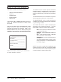
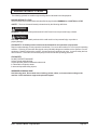
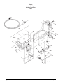
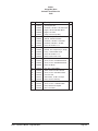
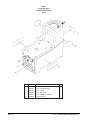
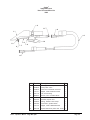
E
Division of
Image
Mini Spot
Operator's
Manual
READ THIS BOOK
This book has important information for the use and safe operation of this machine. Failure to read this
book prior to operating or attempting any service or maintenance procedure to your Clarke machine
could result in injury to you or to other personnel; damage to the machine or to other property could
occur as well. You must have training in the operation of this machine before using it. If you or your
operator(s) cannot read English, have this manual explained fully before attempting to operate this
machine.
Si Ud. o sus operadores no pueden leer el Inglés, se hagan explicar este manual completamente antes
de tratar el manejo o servicio de esta máquina.
All directions given in this book are as seen from the operator’s position at the rear of the machine.
For new books write to: Clarke® , 2100 Highway 265, Springdale, Arkansas 72764.
Form No. 79041B 12/02
Clarke®
Printed in the U.S.A.
MACHINE DATA LOG/OVERVIEW
MODEL _______________________________________
DATE OF PURCHASE ___________________________
SERIAL NUMBER _______________________________
SALES REPRESENTATIVE # _____________________
DEALER NAME _________________________________
OPERATIONS GUIDE NUMBER ___________________
PUBLISHED ___________________________________
YOUR DEALER
Name: _________________________________________________________________________
Address: _______________________________________________________________________
Phone Number: _________________________________________________________________
Page -2-
Clarke® Operator's Manual -Image Mini Spot
Table of Contents
Machine Data Log/Overview .............................................................................................. 2
Table of Contents ............................................................................................................... 3
HOW TO USE THIS MANUAL
How to use this manual ...................................................................................................... 1-1
SAFETY
Important Safety Instructions ............................................................................................. 2-1
Hazard Intensity Level ....................................................................................................... 2-2
Grounding Instructions ....................................................................................................... 2-3
OPERATIONS
Machine Operations ........................................................................................................... 3-1
Set Up and Operation ....................................................................................................... 3-1
Shut Down and Storage ................................................................................................... 3-1
MAINTENANCE
Maintenance Schedule ....................................................................................................... 4-1
Daily Maintenance ............................................................................................................ 4-1
Periodic Maintenance ....................................................................................................... 4-1
Solution Pump Replacement .............................................................................................. 4-1
Vacuum Motor Replacement .............................................................................................. 4-1
Carbon Brush Replacement ............................................................................................. 4-1
Machine Troubleshooting ................................................................................................... 4-2
Wiring Diagram ................................................................................................................... 4-2
GROUP PARTS LIST
Recovery Tank Group ....................................................................................................... 5-1
Solution Tank Group .......................................................................................................... 5-3
Labels & Parts List ............................................................................................................. 5-5
Hand Tool & Parts List ....................................................................................................... 5-6
Spotter Cart & Parts List .................................................................................................... 5-7
Clarke Support Branches ................................................................................................... 5-8
Warranty ............................................................................................................................ 5-9
Clarke® Operator's Manual - Image Mini Spot
Page -3-
THIS PAGE LEFT BLANK INTENTIONALLY
Page -4-
Clarke® Operator's Manual -Image Mini Spot
HOW TO USE THIS MANUAL
This manual contains the following sections:
-
HOW TO USE THIS MANUAL
-
SAFETY
-
OPERATIONS
-
MAINTENANCE
-
PARTS LIST
The HOW TO USE THIS MANUAL section will tell you
how to find important information for odering correct
repair parts.
Parts may be ordered from authorized dealers. When
placing an order for parts, the machine model and
machine serial number are important. Refer to the
MACHINE DATA box which is filled out during the
installation of your machine. The MACHINE DATA box
is located on the inside of the front cover of this manual.
The SAFETY section contains important information
regarding hazard or unsafe practice of the machine.
Levels of hazards is identified that could result in
product or personal injury, or severe injury resulting in
death.
The OPERATIONS section is to familiarize the operator
with the operation and function of the machine.
The MAINTENANCE section contains perventative
maintenance to keep the machine and its components
in good working condition.
The PARTS LIST section contains assembled parts
illustrations and corresponding parts list. The parts
lists include a number of columns of information:
-
MODEL _________________________________________
DATE OF PURCHASE _____________________________
SERIAL NUMBER _________________________________
SALES REPRESENTATIVE # _______________________
DEALER NAME ___________________________________
-
REF - column refers to the reference number
on the parts illustration.
PART NO. - column lists the part number for
the part.
QTY - column lists the quantity of the part
used in that area of the machine.
DESCRIPTION - column is a brief description
of the part.
The main illustration shows the most current
design of the machine. The boxed illustrations
show older designs.
OPERATION GUIDE NUMBER _____________________
PUBLISHED _____________________________________
NOTE: If a service or option kit is installed on your
machine, be sure to keep the KIT INSTRUCTIONS
which came with the kit. It contains replacement parts
numbers needed for ordering future parts.
The model and serial number of your machine is on
the back underside of machine.
Clarke® Operator's Manual - Image Mini Spot
Page 1-1
IMPORTANT SAFETY INSTRUCTIONS
When using an electrical appliance, basic precaution
must always be followed, including the following:
READ ALL INSTRUCTIONS BEFORE USING THIS MACHINE
WARNING:
To reduce the risk of fire, electric shock or injury:
Use only indoors. Do not use outdoors or expose to rain.
Use only as described in this manual. Use only manufacturer's recommended components and attachments.
If this machine is not working properly, has been dropped, damaged, left outdoors, or dropped into water, return
it to an authorized service center.
Do not operate the machine with any openings blocked. Keep openings free of debris that may reduce airflow.
This machine is not suitable for picking up hazardous dust.
Machine can cause a fire when operating near flammable vapors or materials. Do not operate this machine near
flammable fluids, dust or vapors.
This machine is suitable for commercial use, for example in hotels, schools, hospitals, factories, shops
and offices for more than normal housekeeping purposes.
Maintenance and repairs must be done by qualified personnel.
During operation, attention shall be paid to other persons, especially children.
When leaving unattended, secure against unintentional movement.
The machine shall only be operated by instructed and authorized persons.
When leaving unattended, switch off or lock the main power switch to prevent unauthorized use.
Do not handle the plug or machine with wet hands.
Do not unplug machine by pulling on cord. To unplug, grasp the plug, not the cord.
Do not use with damaged cord or plug. Follow all instructions in this manual concerning grounding the machine.
Do not pull or carry by cord, use cord as a handle, close a door on cord, or pull cord around sharp edges or
corners.
Do not pull/run machine over cord. Keep cord away from heated surfaces.
Connect to a properly grounded outlet. See Grounding Instructions.
SAVE THESE INSTRUCTIONS
Page 2-1
Clarke® Operator's Manual -Image Mini Spot
HAZARD INTENSITY LEVEL
The following symbols are used throughout this guide as indicated in their despriptions:
HAZARD INTENSITY LEVEL
There are three levels of hazard intensity identified by signal words- WARNING and CAUTION and FOR
SAFETY. The level of hazard intensity is determined by the following definitions:
WARNING:
WARNING - Hazard or unsafe practices which COULD result in severe personal injury or death.
CAUTION:
CAUTION - Hazards or unsafe practices which could result in minor personal injury or product or
property damage.
FOR SAFETY: To identify actions which must be followed for safe operation of equipment.
Report machine damage or faulty operation immediately. Do not use the machine if it is not in proper operating
condition. Following is information that signals some potentially dangerous conditions to the operator or to the
equipment. Read this information carefully. Know when these conditions can exist. Locate all safety devices
on the machine. Pleae take the necessary steps to train the machine operating personnel.
FOR SAFETY:
DO NOT OPERATE MACHINE:
Unless Trained and Authorized.
Unless Operation Guide is Read and understoood.
In Flammable or Explosive areas.
In areas with possible falling objects.
WHEN SERVICING MACHINE:
Avoid moving parts. Do not wear loose clothing; jackets, shirts, or sleeves when working on the
machine. Use manufacturer approved replacement parts.
Clarke® Operator's Manual - Image Mini Spot
Page 2-2
GROUNDING INSTRUCTIONS
THIS PRODUCT IS FOR COMMERCIAL USE
ONLY.
ELECTRICAL:
In the USA this machine operates on a standard 15
amp 115V, 60 hz, A.C. power circuit. The amp, hertz,
and voltage are listed on the data label found on each
machine. Using voltages above or below those indicated
on the data label will cause serious damage to the
motors.
Grounding Pin
GROUNDING CONNECTION
USING AN ADAPTOR
Grounding
Outlet
Metal Screw
Fig. A
Tab for Grounding
Screw
Adaptor
Adaptor
EXTENSION CORDS:
If an extension cord is used, the wire size must be at
least one size larger than the power cord on the
machine, and must be limited to 50 feet (15.5m) in
length.
GROUNDING INSTRUCTIONS:
This appliance must be grounded. If it should
malfunction or break down, grounding provides a path
of least resistance for electric current to reduce the
risk of electric shock. This appliance is equipped with
a cord having an equipment-grounding conductor and
grounding plug. The plug must be inserted into an
appropriate outlet that is properly installed and grounded
in accordance with all local codes and ordinances.
Adaptor Grounded
Outlet Box
Fig. C
Fig. B
Note: Adaptors are not allowed in Canada.
Improper connection of the equipmentgrounding conductor can result in a risk of
electric shock. Check with a qualified electrician
or service person if you are in doubt as to
whether the outlet is properly grounded. Do not
modify the plug provided with the appliance - if
it will not fit the outlet, have a proper outlet
installed by a qualified electrician.
This appliance is for use on a nominal 120-volt circuit,
and has a grounded plug that looks like the plug in
"Fig. A". A temporary adaptor that looks like the
adaptor in "Fig. C". may be used to connect this plug
to a 2-pole receptacle as shown in "Fig. B", if a
properly grounded outlet is not available. The temporary
adaptor should be used only until a properly grounded
outlet (Fig. A), can be installed by a qualified electrician.
The green colored rigid ear, lug or wire extending from
the adaptor must be connected to a permanent ground
such as a properly grounded outlet box cover. Whenever
the adaptor is used, it must be held in place by a metal
screw.
Page 2-3
Clarke® Operator's Manual -Image Mini Spot
MACHINE OPERATIONS
SET UP AND OPERATION
1.
2.
3.
4.
5.
6.
7.
8.
9.
Upon removing your new mini-extractor from the
box, loosen the latch, at the back end and of the
machine, that secures the recovery tank to the
solution tank. Remove the recovery tank from the
solution tank.
Pour clean, hot water to the indicated fill line of the
solution tank. To avoid possible tank distortion,
water temperature must not exceed 140 F (60C).
Add a non-foaming cleaning solution concentrate,
for use in hot water extractors at the proportions
noted on the container (See list below), into soluiton
tank.
Place the recovery tank back onto the solution tank
and refasten the latch.
Plug the power cord into grounded outlet (See
GROUNDING INSTRUCTIONS).
Connect the vacuum and cleaning tool hoses to the
extractor. This unit is equipped with an 1/8" male
quick connect for solution hose attachement and a
1" ID vacuum hose hookup. Insure that the female
solution hose coupler is securely locked onto the
male coupler on the exttactor.
Turn switch ON. This switch operates both the
vacuum motor and the water pump. NOTE: The
pump is an oscillating pump and should not be run
dry for extended periods of time. This may cause
damage to your pump, therefore voiding your
warranty.
Squeeze the solution lever on the cleaning tool to
spray cleaning solution and place the vacuum head
on the surface to be cleaned. Normally, chemical is
applied ont he push stroke while vacuuming is done
on the pull stroke. For heavily soiled carpets, the
hand tool may be used in the scrubbing manner,
applying chemical in both the push and pull stroke.
ALWAYS FINISH UP AN AREA WITH A VACUUM
PULL STROKE.
The shutoff float inside the recovery tank will
impeded the vacuum flow when the tank is full.
When this occurs, empty the recovery tank. NOTE:
Dispose of waste in a proper manner which would
not violate any Local, State or Federal Law.
WARNING:
Always use defoamer if foaming occurs. Foam will
suspend large particles which may damage vacuum
as well as allow liquid into the vacuum motor without
activating the float shutoff.
WARNING:
To prevent possible disease hazard, before
attempting to clean bodily fluids spills, you must kill
any viruses, germs or bacteria present in the bodily
fluid.
SUITABLE
CHEMICALS
Alkalis
Clorox II Bleach*
Defoaming Agents
Detergents
Hydroxides
Oxygen Bleaches
Bleaches
Soaps
Sta-Puf Fabric
Softner*
Vinegar
CAUTION:
ALWAYS TEST UPHOLSTERY/CARPET FOR COLOR
FASTNESS IN AN INCONSPICUOUS PLACE. Also, to
avoid prolonged drying times, do not spray too much
solution in any one area.
Clarke® Operator's Manual - Image Mini Spot
Chlorinated Hydrocarbons
D-Limonene
Lysol*
Methyls (MEK)
Perchlorethylene (perc)
Phenois
Trichlorethylene
* Registered Trademark
WARNING:
Before making any adjustments or performing any
maintenance to your machine, disconnect the power
cord from the electrical source.
SHUT DOWN AND STORAGE
1.
2.
CAUTION:
Operating vacuum after shutoff has activated could draw
water directly into the vac motor. This will cause damage
to the motor, therefore voiding your warranty.
INCOMPATIBLE
CHEMICALS
Aldehydes
Aromatic Hydrocarbons
Butyls
Carbon Tetrachloride
Clorox*
Chlorinated
3.
4.
5.
Turn switch OFF. Empty recovery tank
completely and rinse several times to remove any
dirt or debris that may be left behind.
Tip the solution tank over a sink to drain any
unused cleaning solution and rinse with clean
water to remove any suds left behind by the
cleaning chemicals. NOTE: Dispose of waste in
a proper manner which would not violate any
Local, State or Federal law.
Run a small amount of clean water through pump
if chemicals were used. This will help insure the
life of your pump.
Check the spray jet on the cleaning tool for full
spray pattern and inspect vac head for any
obstructions. Also make sure to clean the filter
cap attached to portal cover of any debris that
may have been trapped during cleaning.
Remove as much moisture from system before
storing in cold climates. Excess water may freeze
during storage and crack internal components,
causing damage to the unit.
Page 3-1
MAINTENANCE
DAILY MAINTENANCE:
Follow same procedure for Shut Down and Storage:
Vac Motor Carbon Brushes
Replacement
PERIODIC MAINTENANCE:
1. Twice a month, flush a white vineger solution
(one quart vinegar to two gallons water) or anitbrowning solution (mixed as directed) through the
extractor. This will prevent build-up of alkaline
residue in the system.
2. If spray jet becomes clogged, remove the spray
tip, wash it thoroughly, and blow dry. NOTE: DO
NOT USE PINS, WIRE, ETC. TO CLEAN
NOZZLE AS THIS COULD DESTROY THE
SPRAY PATTERN.
3. Apply silicone lubricant to solution nipple.
4. Periodically inspect all hoses, electrical cable
and connections on your machine Frayed or
cracked hoses should be repaired or replaced to
eliminate vacuum or solution pressure loss. If
the cable insulation on the power cord is broken
or frayed, repair or replace immediately. Don't
take chances with electrical fire or shock.
WARNING:
Only qualified maintenance personnel are to
perform the following repairs.
SOLUTION PUMP REPLACEMENT:
1. Turn off all switches and unplug the machine.
2. Unfasten screws holding pump plate to bottom of
solution tank.
3. Remove solution hoses from fittings on pump.
4. Remove pump from brackets and remove fittings
and grounding wire.
5. Reverse process to install new replacement
pump.
VACUUM MOTOR REPLACEMENT:
1. Turn off all switches and unplug machine.
2. Unfasten latch at back end of machine and
remove recovery tank.
3. Unfasten screws holding switch plate to solution
tank. Remove from solution tank. Locate the
vacuum motor wires and disconnect at the
connector.
4. Unfasten screws holding vac plate to switch
plate. Remove the vacuum motor.
5. Reverse process to install vacuum motor
replacement.
Page 4-1
Carbon
Brushes 115V
WARNING: The
green ground wire
must be attached for
safe operation. See
wiring diagram.
NOTE: When replacing carbon vac motor
brushes, loosen wire terminal BEFORE
removing screws on bracket.
If armature commutator is not concentric,
extremely pitted, or grooved, the motor will
need to be replaced or sent to a qualified
service center to restore vac performance.
Important:
These brushes wear
quicker as the length
shortens due to
increased heat.
Spring inside brush
housing will damage
motor if brushes are
allowed to wear away.
Periodically check the length of the carbon
brushes. Replace both carbon brushes when
either is less than 3/8" long.
Clarke® Operator's Manual -Image Mini Spot
TROUBLESHOOTING/WIRING DIAGRAM
TROUBLESHOOTING
PROBLEM
Little or no solution flow
Loss of vacuum/Solution
recovery
CAUSE
SOLUTION
Clogged spray jet on cleaning tool
Remove and clean jets
Faulty pump
Check and replace pump.
(Call Tech. Service first)
Incorrectly attached solution hose
Ensure solution hose coupler is securely
attached to the coupler on the solution tank.
Incorrectly attached vac hose
Ensure vac hose is pushed completely onto
the recovery tank inlet.
Obstruction in cleaning tool
Inspect for and remove any debris
Recovery tank is not securely
mounted on the solution tank
Tighten latch on back end of the machine
WIRING DIAGRAM
Clarke® Operator's Manual - Image Mini Spot
Page 4-2
Clarke®
Image Mini Spot
Recovery Tank Parts
12/02
Parts Inside
Portal Cap
10
13
14
1
9
5
2
11
8
3
7
4
6
12
5
Page 5-1
Clarke® Operator's Manual -Image Mini Spot
Clarke®
Image Mini Spot
Recovery Tank Parts List
12/02
Ref.
Part No.
Description
Qty
1
52875A
Asm. Acess Cover
1
2
3
52876A
52877A
Screw, 8 x 3/4 PFHT/S BLK ZINC
Float Asm. Spotter Weight
6
1
4
5
52878A
52879A
Tube Asm. Spotter
Screw, 10-32 x 3/8 PPHMS SS NP
1
4
6
7
50356A
52796A
Bracket, Rec./Sol. Tank Seal
Gasket, Recovery Tank Seal
1
1
8
9
52880A
52881A
Tank, Spotter Recovery
Plug, Handle Recovery Tank
1
1
10
11
52882A
52883A
Plate, Backsplash Shield
Latch, Tension 3.22L
1
1
12
13
52884A
52885A
Gasket, 2.5" ID x 4" OD x 3/8" T
Foam, Air Filter Spotter
1
ref.
14
52886A
Bushing, 3" PVC Float Shutoff
ref.
Clarke® Operator's Manual - Image Mini Spot
Page 5-2
Clarke®
Image Mini Spot
Solution Tank Parts
12/02
2
24
1
3
4
5
23
22
18
6
28
27
8
16
8
26
9
29
25
10
5
2
11
22
13
14
12
21
18
20
11
15
16
19
17
18
Page 5-3
Clarke® Operator's Manual -Image Mini Spot
7
Clarke®
Image Mini Spot
Solution Tank Parts List
12/02
Ref.
Part No.
Description
1
52887A
Tank, Spotter Sol.
1
2
3
52888A
52889A
Hosebarb, 1/8 NPT x 3/8 90D Plastic
Nipple, 1/8 FPT QD Male Brass
3
1
4
5
52890A
52891A
Nipple, 1/8 Close
Clamp, 3/8 Hose (D-Slot)
1
5
6
7
52892A
52893A
Hose, 3/8" Nylon Braid x 10"
Strainer, 3/8 NPT 60 Mesh
1
1
8
9
52894A
52895A
Hosebarb, 1/8 MPT x 3/8 Plastic
Hosebarb, 3/8 MPT x 3/8 90D
2
1
10
11
52896A
52897A
Hose, 3/8" Rubber x 17"
Nut, 10-32 w/Star Washer Pltd.
1
5
12
13
52898A
52899A
Bracket, PVC Flojet Pump L-Shape
Pump, 110/120 60Hz Flojet
2
1
14
15
52961A
52962A
Hose, 3/8" Rubber x 11"
Plate, Lower Panel Cover
1
1
16
17
52963A
52964A
Washer, #10 Lock Ext. Star
Screw, 10-32 x 1/2 PPHMS SS NP
1
5
18
19
52965A
52966A
Screw, 10-32 x 3/8 PPHMS SS NP
Plate, Vac Motor
13
1
20
21
52967A
52968A
Vac. Asm. 115V Spotter
Switch, SPST 2 Positon Rocker
1
1
22
23
52969A
52970A
Screw, 10-32 x 3/8 HHTR w/Star
Cord, 25' 18/3
4
1
24
25
52971A
52972A
Strain Relief, 1/2 NPT Trumpet
Rivet, 1/8 OD x 3/8 Grip
1
2
26
27
52973A
52974A
Keeper, Tension Latch
Screw, 10-32 x 1 PPHMS GRN
1
1
28
29
52975A
52976A
Plate, Switch/Cord Spotter
Nut, 1/2 Conduit
1
1
Clarke® Operator's Manual - Image Mini Spot
Qty
Page 5-4
Clarke®
Image Mini Spot
Labels and Parts List
12/02
1
6
2
3
4
5
Page 5-5
Ref.
Part No.
Description
Qty
1
52977A
Label, ALTO
1
2
3
52978A
52979A
Label, Image Mini Spot
Label, Clarke
2
2
4
5
52980A
52981A
Label, For Safety
Label, ON/OFF VAC/PUMP
1
1
6
52982A
Label, Warning
1
Clarke® Operator's Manual -Image Mini Spot
Clarke®
Image Mini Spot
Hand Tool and Parts List
12/02
2
11
4
1
3
10
8
5
7
6
9
4
Ref.
Part No.
Description
1
55179A
Housing, Handtool Spotter
1
2
3
52983A
52984A
Clamp DHT Valve
Hose Asm. Hose/Cuff Connector
1
1
4
5
737141
54177A
Nipple, 1/8 FPT QD Fem. Brass
Jet, Asm w/o Ring
2
1
6
7
962802
57011A
Screw, 8-32 x 1/4 PHST PLTD
Plate, Retainer w/Screws
1
1
8
9
56123A
54060A
Manifold, Spotter 3/16
Fitting, 1/8 MPT x 3/16 Comp.
1
1
10
11
59618A
737140
Valve Asm., Spotter Plastic
Nipple, 1/8 FPT QD Male Brass
1
1
Kit
59231R
Spotter Hand Tool (entire asm. as kit) 1
Clarke® Operator's Manual - Image Mini Spot
Qty
Page 5-6
Clarke®
Image Mini Spot
Cart and Parts List
12/02
1
2
3
7
8
4
5
6
Page 5-7
Ref.
Part No.
Description
Qty
1
2
61690A
85520A
Handle Weldment, Cart
Screw, 8-00 x 1/2 Pan Head
1
2
3
4
59951A
920346
Wheel, 8"
Palnut
2
2
5
6
50007A
81110A
Bumper, Recessed
Nut Hex, Elastic Lock, 10-24
1
1
7
8
61689A
962862
Chassis Weldment, Cart
Screw, 10-24 x 1/2 PN ST
1
1
Kit
11678A
Cart (entire asm. as kit)
1
Clarke® Operator's Manual -Image Mini Spot
PRODUCT SUPPORT BRANCHES
U. S. A. Locations
HEAD OFFICE
European Locations
PRODUCTION FACILITIES
ALTO U.S. Inc., St. Louis, Missouri
16253 Swingley Ridge Road, Suite 200
Chesterfield, Missouri 63017-1725
PRODUCTION FACILITIES
Clarke®, Springdale, Arkansas
2100 Highway 265
Springdale, Arkansas 72764
(479) 750-1000
Customer Service - 1-800-253-0367
Technical Service - 1-800-356-7274
American Lincoln®, Bowling Green, Ohio 43402
1100 Haskins Road
SERVICE FACILITIES
Clarke® , Carlstadt, New Jersey 07072
150 Commerce Road
(201) 460-4774
Clarke®, Elk Grove, Illinois 60007
2280 Elmhurst Road
(847) 956-7900
Clarke®, Denver, Colorado 80204
1955 West 13th Ave.
(303) 623-4367
Clarke®, Houston, Texas 77040
7215 North Gessner Road
SALES AND SERVICE FACILITIES
American Lincoln® / Clarke®, Madison Heights,
Michigan 48071-0158
29815 John R.
(810) 544-6300
American Lincoln® / Clarke®, Marietta, Georgia 30062
1355 West Oak Common Lane
(770) 973-5225
Clarke®
Clarke American Sanders
A.L. Cook
Customer Service Headquarters and Factory
2100 Highway 265
Springdale, Arkansas 72764
(479) 750-1000
Technical Service
1-800-356-7274
Clarke® Operator's Manual - Image Mini Spot
ALTO Danmark A/S, Aalborg
Blytaekkervej 2
DK-9000 Aalborg
+45 72 18 21 00
ALTO Danmark A/S, Hadsund
Industrikvarteret
DK-9560 Hadsund
+45 72 18 21 00
SALES SUBSIDIARIES
Clarke® Canada Ltd., Rexdale Ontario
24 Constellation Ct.
(416) 675-5830
ALTO Overseas Inc., Sydney (Australia)
1B/8 Resolution Drive
Caringbah NSW 2229
+61 2 9524 6122
ALTO Cleaning Systems Asia Pte Ltd., Singapore
No. 17 Link Road
Singapore 619034
+65 268 1006
ALTO Deutschland GmbH, Bellenberg (Germany)
Guido-Oberdorfer-Straße 2-8
89287 Bellenberg
+49 0180 5 37 37 37
ALTO Cleaning Systems (UK) Ltd., Penrith
Gilwilly Industrial Estate
Penrith
Cumbria CA11 9BN
+44 1768 868 995
ALTO France S.A. Strasbourg
B.P. 44, 4 Place d’Ostwald
F-67036 Strasbourg
Cedex 2
+33 3 8828 8400
ALTO Nederland B.V. Vianen
Stuartweg 4C
NL-4131 NJ Vianen
+31 347 324000
ALTO Sverige AB, Molndal (Sweden)
Aminogatan 18
Box 4029
S-431 04 Molndal
+46 31 706 73 00
ALTO Norge A/S, Oslo (Norway)
Bjornerudveien 24
N-1266
+47 2275 1770
Page 5-8
Clarke® WARRANTY
This Clarke Industrial Commercial Product is warranted to be free from defects in materials and workmanship under normal use and service for a period of one year from the date of purchase, when operated and
maintained in accordance with Clarke's Maintenance and Operations instructions.
This warranty is extended only to the original purchaser for use of the product. It does not cover normal wear
parts such as electrical cable, rubber parts, hoses and motor brushes.
If difficulty develops with the product, you should:
(a). Return the product to the nearest Clarke repair location. Transportation charges to and from the repair
location must be prepaid by the purchaser.
(b). Clarke will repair the product and or replace any defective parts without charge within a reasonable time
after receipt of the product.
Clarke's liability under this warranty is limited to repair of the product and/or replacement of parts and is
given to purchaser in lieu of all other remedies, including INCIDENTAL AND CONSEQUENTIAL DAMAGES.
THERE ARE NO EXPRESS WARRANTIES OTHER THAN THOSE SPECIFIED HEREIN. THERE ARE NO
WARRANTIES WHICH EXTEND BEYOND THE DESCRIPTION OF THE FACE HEREOF. NO WARRANTIES,
INCLUDING BUT NOT LIMITED TO WARRANTY OF MERCHANTABILITY, SHALL BE IMPLIED.
Clarke, 2100 Highway 265, Springdale, Arkansas 72764.
Clarke reserves the right to make changes or improvements to its machine without notice.
Always use genuine Clarke Parts for repair.
Division of
2100 Highway 265
Springdale, Arkansas, 72764