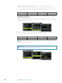
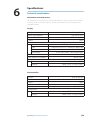
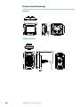
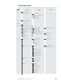
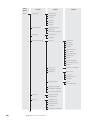
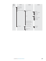
1
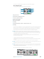
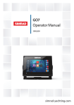
Triton Operation Manual ENGLISH bandg.com Preface As Navico are continuously improving this product, we retain the right to make changes to the product at any time which may not be reflected in this version of the manual. Please contact your nearest distributor if you require any further assistance. It is the owner’s sole responsibility to install and use the instrument and transducers in a manner that will not cause accidents, personal injury or property damage. The user of this product is solely responsible for observing safe boating practices. NAVICO HOLDING AS AND ITS SUBSIDIARIES, BRANCHES AND AFFILIATES DISCLAIM ALL LIABILITY FOR ANY USE OF THIS PRODUCT IN A WAY THAT MAY CAUSE ACCIDENTS, DAMAGE OR THAT MAY VIOLATE THE LAW. Governing Language: This statement, any instruction manuals, user guides and other information relating to the product (Documentation) may be translated to, or has been translated from, another language (Translation). In the event of any conflict between any Translation of the Documentation, the English language version of the Documentation will be the official version of the Documentation. This manual represents the product as at the time of printing. Navico Holding AS and its subsidiaries, branches and affiliates reserve the right to make changes to specifications without notice. Copyright Copyright © 2012 Navico Holding AS. Warranty The warranty card is supplied as a separate document. In case of any queries, refer to the brand web site of your display or system: www.bandg.com About this manual This manual is a reference guide for operating the B&G Triton instrument and Pilot controller. It assumes that all equipment is installed and configured, and that the system is ready to use. The manual assumes that the user has basic knowledge of navigation, nautical terminology and practices. Important text that requires special attention from the reader is emphasized as follows: Note: Used to draw the reader’s attention to a comment or some important information. Warning: Used when it is necessary to warn personnel that they should proceed carefully to prevent risk of injury and/or damage to equipment/personnel. Preface | Triton Operator Manual |3 The software This manual is written for B&G Triton Release to Market 1 (RTM1). Please check web site for details on the current release version. Note: The menu route shown above is an example only and may not match the software installed on your unit! Note: To update the software you will need a compatible multifunction display / chartplotter running on the network. eg. B&G Zeus multi function display (MFD). If you do not have a suitable device on the network you can arrange to update the software via a B&G dealer. You can download the latest version of the software from www.bandg.com and upgrade the displays via the B&G MFD, instructions on how to do this can be found on the B&G website. www.bandg.com Note: The manual may have been updated to match new software releases. The latest available manual version can be downloaded from www.bandg.com Note: Portions of this software are copyright © 2011 The FreeType Project (www.freetype.org). All rights reserved. 4| Preface | Triton Operator Manual Contents 7 Operation 7 8 9 13 14 15 16 17 18 19 The Triton Display and Pilot Controller Pages Default pages Replacing a data page Template pages Customizing a template page Auto scroll Timer Log Alarms 23 Setup 23 24 29 30 31 31 32 32 32 33 33 34 Sources Device list Time & Date Units Display mode Display setup Damping Decimal places Magnetic variation Sounds System Diagnostics 35 Autopilot 35 35 36 37 37 38 38 39 39 40 42 42 Overview Operation Pilot Controller Turning the Pilot on / off Autopilot operational modes Autopilot symbols Selecting a Pilot mode Standby mode (Manual helm steering) Auto mode (Compass steer mode) Wind mode Non follow up mode Navigation mode (Steer to waypoint) 45 Autopilot settings 45 45 46 47 49 51 52 52 53 56 Installation menu Commissioning Dockside Rudder drive Sea trial Pilot response Sea state filter Sailing Automatic steering Reset Contents | Triton Operator Manual |5 6| 57 Maintenance 57 General maintenance 59 Specifications 59 Technical specifications 60 Dimensional drawings 60 60 Display Pilot controller 61 Menu flow chart Contents | Triton Operator Manual 1 Operation The B&G Triton system is a networked multifunction instrument display and Pilot controller. The display shows speed, depth, heading, position, wind and environmental data measured by sensors and other equipment connected to the system. Navigational data, engine/battery status and vessel parameters such as accumulated log and rudder angle may also be displayed. The instrument calculates speed trim, wind, trip distance and time, average speed, set and drift parameters. A race timer is also included. If a compatible autopilot is installed and connected to the same network it can be controlled by the Pilot controller. The Triton Display and Pilot Controller 1 5 6 4 3 2 7 8 9 1 Display 2 Menu / Enter key Used to enter the main menu, select sub menus and confirm selection. Note: Press and holding the Enter key for 3 seconds takes you directly to the display setup lighting level screen. If the lighting level is set below 5 it will automatically increase to 5. Use the up and down keys to set the desired level and press Enter to confirm. 3 Page key Scrolls through the eight default display pages and navigates back a step in menus. Note: the eight default display pages including Pilot page can be customized to display the required data. 4 Directional keys Scrolls up and down through selected menus / set values. 5 Pilot Controller 6 Mode key Changes the Pilot mode. 7 Off key Disengages the autopilot. 8 Course control keys Changes target course / Activates Non Follow Up (NFU) mode when in Standby mode. 9 Auto key Engages the autopilot. Operation | Triton Operator Manual |7 Pages From new the display shows eight default data pages. Data pages show a variety of boat data and information available from sensors and devices on the Network. The display default pages show: Basic speed/depth, wind composite, basic wind/speed, steering, depth history, GPS, highway and autopilot. Each press of the page key will change the current data page to the next preselected page in the cycle. Note: Pressing the page key will change the data pages in sequence and in continuous rotation. You can choose to have up to eight pages as part of the data page cycle, these can be any combination of the eight default and nine template pages available from the pages menu. Note: Only seven pages will be available when in Instrument Only display mode. Note: Two or more pages need to be enabled for the page key to function. 8| Operation | Triton Operator Manual Default pages Basic Speed / Depth Two line data display. Boat speed and Depth Wind Composite The wind composite page presents the following information: 1 2 3 5 6 7 4 8 9 1 Apparent wind speed (AWS) 2 Red - Close hauled port tack 3 Boat orientation. (Always pointing forwards) 4 True wind speed (TWS) 5 Apparent wind angle (AWA) 6 Green - Close hauled starboard tack 7 Apparent wind angle graphic 8 True wind angle graphic 9 True wind angle (TWA) Basic Wind / Speed Two line data display. Apparent Wind Angle and True Wind Speed 1 2 1 Wind angle indicator - Green arrow right = Starboard tack. Red arrow right = Port tack 2 Beaufort scale indicator Operation | Triton Operator Manual |9 Steering The Steering page presents the following information: 6 1 2 3 4 5 7 8 9 10 1 Compass graphic (Heading) 2 Heading 3 Bearing to waypoint (BTW) 4 Off track limit 5 Rhumb line 6 Bearing to waypoint indicator 7 Course over ground (COG) 8 Cross track error (XTE) R = Right / L = Left 9 Cross track error graphic 10 Boat position from rhumb line Depth History Current depth and histogram of recorded depth data. 1 2 3 1 Depth value 2 Boat type - Sail or Motor boat image 3 Depth graphic Note: You can adjust the time period scale via the up & down keys. 10 | Operation | Triton Operator Manual GPS The GPS page presents the following information: 2 3 6 7 1 4 5 8 1 Coordinate system 2 Boat position (Latitude & Longitude) 3 Course over ground (COG) 4 Local time 5 Speed over ground (SOG) 6 Bearing to waypoint (BTW) 7 Estimated time of arrival (ETA) 8 Distance to waypoint (DTW) Note: GPS information relies on a suitable GPS connected to the network and selected on the display as the current GPS. Highway The Highway page presents the following information: 2 1 3 4 5 6 7 1 Waypoint name 2 Estimated time of arrival (ETA) 3 Next waypoint 4 Highway graphic 5 Bearing to waypoint (BTW) 6 Cross track error (XTE) 7 Distance to waypoint (DTW) Operation | Triton Operator Manual | 11 Autopilot The Autopilot page presents the following information: 5 6 7 8 1 2 3 4 1 Response mode 2 Pilot mode 3 Compass graphic (Heading) 4 Rudder angle graphic 5 Set heading / Wind angle / Rudder angle 6 Current heading / Wind angle 7 Set heading indicator - Green = Starboard / Red = Port 8 Heading Pilot modes The current heading and Set heading information will change on the display depending on which mode the pilot is in. Below is a list of the pilot modes, pilot mode symbol and the current/target data that will be displayed. 1 2 3 1 Pilot mode / Pilot mode symbol 2 Current 3 Target Pilot Mode Standby Auto Non FollowUp Navigation Wind 12 | Symbol S A NFU N W Operation | Triton Operator Manual Current Target Heading N/A Heading Set heading Heading Rudder Angle Heading Set heading True Wind Angle (TWA) Apparent Wind Angle (AWA) Set Wind Angle Response modes The response mode is next to the Pilot mode symbol. Select auto or hi/low manual modes from the pilot response settings in the pilot menu. Response Mode Auto Hi Lo Symbol Hi-A Lo-A Hi-M Lo-M Description When set to Auto the pilot will automatically select a high or low response mode determined by boat speed and wind angle Manual selection of Hi response mode Manual selection of Lo response mode Replacing a data page Go to the pages menu. Select the page you wish to replace then select the new page you would like to replace it with. Enabling a data page To make a data page available via the page key you will need to first ensure it has been selected as one of the eight available pages. Once the page has been selected as one of the eight data pages you can enable it by selecting Enable Page. Once selected a tick will be visible in the check box. Operation | Triton Operator Manual | 13 Template pages There are nine template pages that can be configured to display specific data suited to the user. Chose from the following: Template Page Symbol Single Line One piece of data Two Line Two pieces of data on a split level, top and bottom Four Panel Horizontal Four pieces of data. One on top and three below Four Panel Equal Four pieces of data. Split equally Nine Panel Nine pieces of data. Split equally 0.0 14 | Description Histogram Displays data as a histogram with a data value shown above Analogue Displays data as an analogue display Full Screen Analogue Displays data as a full screen analogue display Highway Highway graphic with three pieces of data below Operation | Triton Operator Manual Customizing a template page Once selected you can change the displayed data by editing the page. Change data You can edit a template page so it displays the specific information that you require. Note: A template page cannot be edited until it has been selected as one of the eight data pages. To change the display data shown on a template page first select the template from the pages menu. In the action menu select Change Data. Highlight the desired field in the page you wish to edit and press ‘Enter’ Note: Use the directional keys on the display to navigate between the individual data fields. Pressing the directional key in one direction will change the highlighted field in sequence and in continuous rotation. Once the data field has been selected you can chose the data type you wish to place in this field from the menu. Select the data type by pressing ‘Enter’ Once selected a tick will appear in the check box. The required data will now appear in the selected field. To populate other blank fields repeat the process. Note: If a data type is selected but there is no sensor on the network providing the information there will be no data reading on the display. Instead there will be dashes. Note: Press the page key at anytime to return to the template. Operation | Triton Operator Manual | 15 Auto scroll When selected, auto scroll automatically scrolls between the enabled pages at a timed interval predetermined by setting the desired scroll time in the auto scroll settings menu. Include in auto scroll To include a page in auto scroll, go to the auto scroll settings in the action menu of the specific page and select Include in auto scroll. Once selected a tick will appear in the check box. Auto scroll settings In the auto scroll settings menu you can start the auto scroll function and set the time interval between page changes. Note: The scroll time interval can be set to change the displayed data page between 1 and 10 second intervals. Start auto scroll To start auto scroll, select any of the data pages from the pages menu, select Auto scroll settings and select Start auto scroll. Once selected a tick will appear in the check box and the display will scroll through the pages on a cycle set to the desired auto scroll interval. To stop auto scroll deselect Start auto scroll. Note: You can set the time interval of the screen transition from this menu, by selecting Scroll time and modifying the interval time. 16 | Operation | Triton Operator Manual Timer The timer can be used as a countdown timer to a race start and as a means of measuring the time elapsed after a race start or for any other timed operation. Note: The timer is by default shared between interconnected displays on the network. All timer values will be identical. The timer can be started at any time by selecting Start Timer from the timer setup menu. If the Start value is set to zero (00:00) when the timer is started the timer will begin counting up, recording the elapsed time. Note: The timer set value is in hours : Minutes, the timer counter will show Minutes : Seconds with the hours in the top right hand corner of the display. Countdown Timer If you want to count down to a race start a time value can be set in the Start Value field in the timer setup menu. When a time is present in the start value field the timer will begin to countdown from that number when the timer is started. Once the time reaches zero it will begin counting up recording the elapsed race time. Note: Time format = Hours (Shown in the top right-hand corner) Minutes : Seconds (MM:SS). Start Value To set a start value. Highlight and select Start Value. Pressing the ‘Page’ key will scroll through the race timer digits from left to right. When the desired number is highlighted, scrolling up and down will change that digit. Once complete press ‘Enter’ to confirm. Note: Minimum timer value greater than zero is one minute. Start/Stop Timer Once a start value has been set, to start the timer, highlight Start timer and press ‘Enter’. The display will turn to the timer page and begin counting accordingly. To stop the timer from counting select Timer Setup , highlight Stop Timer and press ‘Enter’. Operation | Triton Operator Manual | 17 Reset Timer Selecting Reset timer will reset the timer to the start value. If the timer was running, it will continue to run from the start value. Start Trip on Running When selected the trip log will record your time and millage from the moment the countdown clock begins counting up from zero. Nearest Full Minute When the timer is counting down selecting Nearest Full Minute will synchronize the time up or down to the nearest full minute. Log The Log page presents the following information: 1 3 2 4 1 Current trip distance 2 Current time 3 Total logged distance 4 Current date The log shows the current time and date, total recorded distance for the instruments life time and trip log showing total distance travelled from the time of the trip reset and the selection of Start trip. Once started it will change to Stop trip. The trip log counter will continue to count up until it is stopped. Note: The Log and Date cannot be reset. The date is taken from the global time and date settings. The time can be set to correspond with your global position. 18 | Operation | Triton Operator Manual Reset trip and time To reset the trip and time to zero select Reset trip and time. Alarms If you have the relevant sensor connected to the network you can enable the corresponding alarm by selecting it from the Alarms list. Alarm on / off Turn an alarm on or off from the alarm list. A tick symbol next to the alarm in the alarm list will indicate that the alarm is on. Note: It is possible to disable all alarms by selecting Disable all alarms Setting alarm parameters Selecting an alarm that requires parameters to be set will take you to its alarm page. Set the required parameter, select Enabled and select OK once complete. The alarm can be disabled by deselecting Enabled. Below is an example of how to set a shallow water alarm. Select Enabled and set the desired depth. Operation | Triton Operator Manual | 19 Alarm indication The alarm system is activated if any alarm settings are exceeded. When an alarm is notified, the alarm will be indicated with an alarm text and with an audible alarm. There are two types of audible alarm indication. Single alarm tone or continuous alarm tone. Note: See Alarm settings for further details on how to set an alarm. Note: If a Pilot is not on the network all Pilot alarms will be greyed out and will not be accessible. If the display is connected to other Network units, any alarm in the system will be displayed on the instrument. If no specific alarm text is displayed, an alarm code will appear. Acknowledging an alarm An alarm is acknowledged by pressing the ‘Enter’ key. This will remove the alarm notification (text, light and sound) from all units that belongs to the same alarm group. A reminder will reappear at given intervals for as long as the alarm condition exists. Note: An alarm received from other networked units must be acknowledged on the unit generating the alarm. 20 | Operation | Triton Operator Manual Alarm types Alarm Value Disable all alarms OFF Alarm description Type All alarms off.- NO Alarms will be raised! Cont’ Shallow water m Shallow water limit - Meters Cont’ Deep water m Deep water limit - Meters Cont’ High wind kn Max wind speed - Knots Cont’ Off course nm Max off course distance - Nautical miles Cont’ N/A Use when at anchor. The alarm will sound when there is a significant change of depth caused by a change in tide or boat drifting into deeper or shallower water. The anchor depth alarm value is predefined in the software and cannot be configured by the user. The anchor alarm should be turned off when the boat is not at anchor. Cont’ Anchor alarm Pilot system alarms only Wind shift º Maximum wind shift - Degrees Cont’ Depth data missing N/A Single Wind data missing N/A Single Navigation data missing N/A Single Missing data Compass data missing N/A Single Speed data missing N/A Single Position data missing N/A Single Rudder feedback failure N/A Cont’ Rudder response failure N/A Cont’ Drive overload N/A Single High temperature N/A Single Bypass/clutch overload N/A Single Bypass/clutch disengaged N/A Single Pilot failure High drive supply N/A Single Low drive supply N/A Single No active control unit N/A Single No autopilot computer N/A Single ACXX Memory failure N/A Single RF must be calibrated N/A Single Key: Alarm type. Single = Single sound alarm, Cont’ = Continuous sound alarm. Both types of alarm will have a notification appear on the display until the alarm is acknowledged. Operation | Triton Operator Manual | 21 22 | Operation | Triton Operator Manual 2 Setup Sources A data source can be a sensor or a device connected to the NMEA2000 network, providing information and commands to other networked devices. The data sources are normally configured at first time turn on. It should only be necessary to update this data if a new source is added, source is missing (sensor failure), source has been enabled/disabled, sensor replaced or a network reset. Auto select The Auto select option will look for all sources connected to the instrument system. If more than one source is available for each item, the display will automatically select from the internal device priority list. 1: Verify that all interfaced units are powered on 2: Press the ‘Enter’ key to start the auto select procedure The operator will be noted when the auto select process is completed. Note: If more than one source is available on the network you can chose your preferred source from the sources menu. See Manual source selection for more information. Setup | Triton Operator Manual | 23 Manual source selection If more than one source is available for an item, the preferred source may be selected manually. As an example, the following illustrations show how the compass source is changed. Select the preferred data source. The selected source will be indicated by a tick in the check box. Device list Shows a list of devices connected to the Network. Selecting a device from the list will show you an information pane with details of that device. Some devices such as an RC42 compass store their configuration, calibration and offset data in their own memory and not in the display memory. For devices of this type you can check the data information, configure and calibrate the device by selecting Options. Data The data list shows the data type that the device is transmitting. Configure Instance Enter a number to differentiate between instances of the same device. Offset Certain devices will let you enter an offset value to compensate for the position of the sensor or variation of sensor data. Note: Some devices can be configured further. If a device transmits other data it may be shown on this page also. Calibrate For compass sensors only, once installed you will need to calibrate the device Select Calibrate and follow the instructions on the display. 24 | Setup | Triton Operator Manual Boat speed Speed calibration is necessary to compensate for hull shape and paddlewheel location on your boat. For accurate speed and log readings, it is essential that the paddlewheel is calibrated. Boat speed values can be shown in knots, kph or mph. Your preferred unit of measurement can be set in the units page of the setup menu. Auto - Calibration via reference to GPS SOG value This is an AutoCal facility that uses speed over ground (SOG) from your GPS and compares the average of SOG against the average boat speed from the speed sensor for the duration of the calibration run. Note: This calibration should be made in calm sea with no effect from wind or tidal current. 1. Bring the boat up to cruising speed (above 5 knots) 2. Select Auto on the Boat speed calibration page 3. When the calibration is completed the Boat speed calibration scale will show the adjusted percentage value of the boat speed. USE SOG as boat speed If boat speed is not available from a paddle wheel sensor it is possible to use speed over ground from a GPS. SOG will be displayed as boat speed and used in the true wind calculations and the speed log. Setup | Triton Operator Manual | 25 Manual adjustment of boat speed Adjust the boat speed manually by selecting the Boat speed percentage slider. Adjust the percentage up or down as desired. Confirm the value. Select OK once complete. Distance Reference This facility enables the user to calibrate the log accurately and simply. Calculations are performed by the display that works out the boat speed over a known distance. To calibrate the boat speed via a distance reference you will need to complete consecutive runs, under power at a constant speed made along a given course and distance. Note: To eliminate the effect of tidal conditions it is advisable to perform at least two runs, preferably three, along the measured course. How To Calibrate via Distance Reference Enter the desired distance in nautical miles that you would like to calculate the distance reference over. When the boat gets to the predetermined starting position of the distance reference calculation start the calibration timer. 26 | Setup | Triton Operator Manual Distance reference diagram Referring to the diagram reference diagram, A and B are the markers for each run and X is the actual distance for each run as ascertained from a suitable chart or GPS for example. A X B Start Run 1 Stop Run 1 Start Run 2 Stop Run 2 Start Run 3 End Calibration As the boat passes marks A and B on each run, instruct the system to start (Start Run) and stop (Stop Run) and finally OK to end calibration (End Cal Runs). After the last run is completed and OK has been selected, a pop up warning will ask you if you wish to replace the current calibration with the new one. Select Yes to complete. Depth A typical transducer installation is through the hull in front of the keel. A datum (offset value) can be set, such that the depth display refers to either the water line or the base of the keel. +VE: Positive Datum for Waterline (0.0) - VE: Negative Datum for Keel Setting the depth offset displays depth readings from directly below the keel or propellers of the boat, or from the waterline to the seabed. This makes it easier to see the available depth, taking into account the draught of the boat. Setup | Triton Operator Manual | 27 The offset value to be entered should represent the distance between the face of the depth transducer, and the lowest part of the boat below the waterline, or the distance between the face of the depth transducer and the water surface. Sea Temperature If a suitable temperature sensor is fitted, the system will monitor the current sea temperature. The offset value to be entered should adjust the temperature reading from the sensor to match a calibrated thermometer when submersed in the water Apparent Wind This provides an offset calibration in degrees to compensate for any mechanical misalignment between the masthead unit and the center line of the vessel. To check the masthead unit alignment error we recommend you use the following method which involves a sailing trial. Sail on a starboard tack on a close hauled course and record the wind angle, then repeat the process on a port tack. Divide the difference between the two recorded numbers and enter this as the wind angle offset. WIND Starboard Tack Port Tack 33º 27º Starboard tack = 33º Port tack = 27º Difference: 33º - 27º = 6º Offset: 6º/2 = -3º If the starboard apparent wind angle is greater than the port angle then divide the difference by 2 and enter this as a negative offset. If the port angle is greater than the starboard then divide the difference by 2 and enter this as a positive offset. 28 | Setup | Triton Operator Manual Compass Heading The compass offset compensates for fixed errors (misalignment) between the compass sensor and the direction of the boat. To accurately enter a compass offset, the boat’s heading must be referenced to, for example: a calibrated bowl compass . The offset value will be the difference between the known source and the currently displayed heading. Enter this value as the offset in the compass heading field as a plus or minus integer up to 180º USE COG as heading If heading data is not available from a compass sensor it is possible to use course over ground from a GPS. COG will be displayed as heading and used in the calculation of true wind direction. Note: The autopilot cannot be operated using COG as the heading source. COG cannot be calculated when stationary. Time & Date From the time and date menu you can set your preferred time / date format and local time offset. Once complete select Save to save your settings and exit. Note: Local time is calculated based on UTC provided via a GPS unit connected to the network. Setup | Triton Operator Manual | 29 Units Set the preferred unit of measurement you want data to be displayed in. Parameter Options Default value kn Knots Boat speed kph Kilometers per hour kn mph Miles per hour kn Knots Wind speed m/s Meters per second kn mph Miles per hour nm Nautical miles Distance mi Miles nm km Kilometers ft Feet Depth m Meters ft fa Fathoms Heading Temperature Volume ºM Magnetic ºT True ºF Fahrenheit ºC Centigrade gal Gallons L Liters ºM ºF gal Hg Inches of Mercury Pressure mb Millibars mb hPa Hectopascal Note: If magnetic variation is not available via a GPS an offset can be entered manually. See Magnetic variation for more information. The same applies if the user wants to read magnetic heading, but only receives true heading from the compass. Language The display can be set to different languages to suit your preference. 30 | Setup | Triton Operator Manual Display mode There are 3 display functionality modes. Highlight the desired mode and press ‘Enter’ to select. Instrument display only Displays instrument data only. No Pilot data page is viewable. Pilot display only Displays Pilot data only. No instrument data pages are viewable. Pilot when engaged Possible to view instrument data pages at all times and Pilot data when a Pilot system is installed and connected to the network. Note: The Pilot page is automatically displayed when the Pilot is engaged. Display setup Set the light zone, enter night mode and change the lighting level. Note: Press and holding the ‘Enter’ key for 3 seconds takes you directly to the display setup lighting level screen. If the light level is set below 5 it will automatically increases to 5. Use the up and down keys to set the desired level and press ‘Enter’ to confirm. Lighting zone Set the lighting zone on the display. All units in the selected lighting zone will mirror each others light settings. Default setting is Network. Night mode Change the display to night mode colour pallet. All displays in the selected lighting zone will also change to night mode. Lighting level Adjust the back light level from 1 - 10. Setup | Triton Operator Manual | 31 Boat type Select the type of boat that is installed on. Chose either Sail or Power depending on the vessel. Damping The damping rate effects the frequency that the sensor data is updated on the display, the greater the damping value the smoother the number change will be but the slower the response will be to data change. Decimal places It is possible to change how many decimal places speed and sea temperature data will be displayed with. Choose how many decimal places you wish to have shown for that specific data type. Magnetic variation Adjust how the system handles magnetic variation. Auto Automatically calculates variation based on position and time. Manual If variation is not available enter a value manually. 32 | Setup | Triton Operator Manual Sounds Turn the keypress and alarm sounds on or off. Note: Silencing the alarm sound does not deactivate the alarms. When an alarm is activated the warning notification will be shown on the display regardless of the sound being on or off. System From the system menu there are several options to reset the system, place the display into simulator and get the current software information. Reset options There are a variety of reset options available from the system menu. Note: Whenever a reset option is selected there will be a dialog box asking you to confirm that you wish to reset before any further action is taken. If you wish to cancel the reset, select No will return you to the system menu. Network reset Resets the source selection on all displays connected to the network. Autopilot reset Resets the Pilot and returns all settings to factory defaults. Warning: The Pilot will need to be commissioned before it is fit for purpose. Do not engage the autopilot until it has been commissioned and a sea trial has been completed. Setup | Triton Operator Manual | 33 Reset to Factory Resets the current display to the default settings. When the unit is restarted you will see the original startup wizard asking you to set the display. Warning: All settings for instrument and Pilot will be restored to factory default. The Pilot will need to be commissioned before use. Simulator Simulator mode sends simulated data to the display. Warning: It is not advisable to enter simulator mode when using your instrument system as a navigation aid. Software Information Shows the software version currently installed on the display. Press ‘Enter’ or the ‘Page’ key to navigate back to the menu. Diagnostics Shows an overview of the data being transmitted on the network, The list shows the network bus status, bus load as a percentage as well as quantity and type of data messages. Note: We recommend that you use this diagnostic tool as a basic overview of the network status. For more detailed information it is suggested that you check the individual source information via the device list. 34 | Setup | Triton Operator Manual Autopilot 3 Overview If a Pilot control system is installed and connected to the network then you will be able to see the Pilot functionality on your display. The autopilot is designed to maintain an accurate course in all sea conditions with minimal movements to the rudder. As the autopilot steers so accurately, it will get you to your destination faster and more efficiently, especially when navigating to a waypoint or following a route. All Pilot functionality and data can be accessed via the display but the Pilot Controller must be installed to operate all of the Pilot core functions. Operation Warning: An autopilot is a very useful navigational aid, but DOES NOT under any circumstances replace a human navigator! Warning: Ensure the Pilot has been installed correctly, commissioned and calibrated before use. Note: You can switch from Auto to Standby mode at anytime by pressing the Off key on the Pilot controller. • • • • • • • Do not use automatic steering when: In heavy traffic areas or in narrow waters In poor visibility or extreme sea conditions When in areas where use of autopilot is prohibited by law When using an autopilot: Do not leave the helm unattended Do not place any magnetic material or equipment near heading sensor used in the autopilot system Verify at regular intervals course and position of vessel Always switch to Standby mode and reduce speed in due time to avoid hazardous situations Autopilot | Triton Operator Manual | 35 Pilot Controller Keys The Pilot controller is operated by 7 keys, these are used to operate the pilot and adjust pilot parameters. Connectors The Pilot controller is equipped with 1 Network connector at the rear. Network The pilot controller can be connected at any point on the network. Keys Function Mode: Changes the Pilot mode. When in Auto mode pressing the mode key will change the Pilot to Wind mode. A long key press will change to Navigation mode which will require confirmation via the display before it is engaged. Off : Disengages the autopilot. Places the autopilot into Standby mode. Left 1: Adjust the set course or wind angle 1 degree / steer to Port in Non follow up mode. When pressed in Standby mode this will enter the Pilot into Non Follow Up mode. Right 1: Adjust the set course or wind angle 1 degree / steer to Starboard in Non follow up mode. When pressed in Standby mode this will enter the Pilot into Non Follow Up mode. Left 10: Adjust the set course or wind angle 10 degrees / steer to Port in Non follow up mode. When pressed in Standby mode this will enter the Pilot into Non Follow Up mode. Right 10: Adjust the set course or wind angle 10 degree / steer to Starboard in Non follow up mode. When pressed in Standby mode this will enter the Pilot into Non Follow Up mode. Auto: Engage the autopilot / Acknowledge tack/gybe or navigation course change. 36 | Autopilot| Triton Operator Manual Turning the Pilot on / off Engaging the Pilot At anytime while the Pilot is disengaged press the ‘Auto’ key to engage the Pilot. The Pilot will steer the boat on the current selected course. Disengaging the Pilot At any time the Pilot is engaged press the ‘Off ’ key to disengage the Pilot. The Pilot will go into standby mode and you will be required to take manual control of the helm. Warning: In Standby mode pressing any of the directional keys will engage the Pilot in Non follow up mode! Autopilot operational modes Below is a list of autopilot modes that can be initiated via the Pilot Control Mode Boat Type Motor Standby Sail Description Required Input Passive mode used when manually steering the boat at the helm Keeps the boat on set heading Auto Cancels the turn and continues on the heading read from the compass Heading Navigation Steers the boat to a specific waypoint location, or through a route of waypoints Heading / Speed / Position / Waypoint Route information Wind Steers the boat to maintain the set wind angle Heading / Speed / Wind Angle Non Follow Up Steer the boat manually using the Pilot Controller Autopilot | Triton Operator Manual | 37 Autopilot symbols More Pilot modes are available via a compatible chart plotter connected to the network. Any Pilot mode selected via the chartplotter will be shown on the display. Below is a list of Pilot modes and their symbols accessible via the Pilot controller.. Mode Symbol S A W N NFU Function / Mode Standby Auto (Compass) Wind Navigation Non Follow Up (Power steer) Note: The Pilot mode can be selected or changed at anytime via the display or compatible chart plotter connected to the Network. Selecting a Pilot mode Press the ‘Auto’ key to activate the Pilot. Press the ‘Mode’ key for wind or long press for navigation mode. Note: Wind mode can only be selected when the Pilot boat type is set to sail. Note: The Pilot must be in Auto mode before other modes can be selected. Note: Press the ‘Auto’ key to enter Auto mode or accept a tack/gybe or navigation course change. Press the ‘Off’ key to place the Pilot into Standby mode. 3 SEC Note: The display will not update until the Pilot engages the new selected mode. 38 | Autopilot| Triton Operator Manual Standby mode (Manual helm steering) The autopilot must be in Standby mode when you steer the boat at the helm. You can switch the autopilot to Standby mode from any operation by a short press on the ‘Off ’ key. Auto mode (Compass steer mode) When the ‘Auto’ key is pressed, the autopilot selects the current boat heading as the set course. The autopilot will keep the boat on the set course until a new mode is selected or a new course is set with the ‘Course’ keys. Once the course is changed to a new set course, the boat will automatically turn to the new heading and maintain the new course. Note: The Pilot will continue to steer to the set heading until the mode is changed or the Pilot is turned off (disengaged) Pilot - Auto page The wind display presents the following information: 5 6 7 8 1 2 3 4 1 Response mode 2 Pilot mode: A = Auto mode 3 Compass graphic (Heading) 4 Rudder angle graphic 5 Set Heading 6 Heading 7 Set heading indicator - Green = Starboard / Red = Port 8 Heading Steering via the Pilot controller Steer port, 1°/press Steer port, 10°/press Steer stbd., 10°/press Steer stbd., 1°/press Regain manual steering by pressing the ‘Off ’ Key Autopilot | Triton Operator Manual | 39 Wind mode When the autopilot is set to Wind steer mode the Pilot uses the current apparent wind angle and maintains that angle as the auto steered course. Press the ‘Mode’ key until the wind mode symbol is visible in the mode field on the display. The autopilot will keep the boat on that wind angle until a new mode is selected or a new wind angle is set with the ‘Arrow’ keys. Once a new angle is selected, the boat will auto steer to maintain the new angle. Warning: In wind mode the autopilot steers to the apparent or true wind angle and not to a compass heading. Any subsequent wind shift could result in the vessel steering on a undesired course. Note: The Wind mode is only available if the system has been set up for SAIL-boat in the Installation Menu. Prior to entering Wind mode the Pilot system should be operating in Auto, with valid input from the wind transducer. Enter the Wind mode by pressing the ‘Auto’ key then the ‘Mode’ key until W appears in the top left corner of the display. 40 | Autopilot| Triton Operator Manual Pilot - Wind page The wind display presents the following information: 1 2 3 5 6 7 8 4 1 Response mode 2 Pilot mode: W = Wind mode 3 Compass graphic (Heading) 4 Rudder angle graphic 5 Wind angle 6 Apparent / True Wind angle (depending on wind setting) 7 Set heading indicator - Green = Starboard / Red = Port 8 Heading The set heading and set wind angle are entered from the compass heading and the masthead unit at the moment the Wind mode is selected. From that point the autopilot will change the course to maintain the wind angle as the wind direction may change. Note: If the cumulative shift of the wind direction exceeds a set limit a Wind SHIFT alarm will sound. Tacking in Wind mode Tacking in Wind mode can be performed when sailing with apparent or true wind as the reference; the true wind angle should be less than 90 degrees. The tacking operation will immediately mirror the set wind angle on the opposite tack. A tack window will appear on the display. The rate of turn during the tack will be given by the Tack time parameter set in the Setup/Sailing menu. The tack time is also controlled by the speed of the boat to prevent loss of speed during a tack. Autopilot | Triton Operator Manual | 41 Tack & Gybe in wind mode To tack or gybe in wind mode press both 1º course keys on the Pilot controller. When you enter a command to tack in wind mode a pop up will appear on screen asking you to confirm the desired action. Press ‘Enter’ to accept. Pressing ‘Enter’ on the display or ‘Auto’ on the Pilot controller will activate the tack/gybe function and the boat will start turning to the opposite wind angle. Note: To cancel the tack/gybe request, press the ‘Off’ key on the Pilot controller or select cancel using the display. If neither Tack or Cancel is selected the tack/gybe pop up will close after 10 seconds and return to the Pilot display and the requested tack/gybe will not be initiated. Note: The Pilot will add a 5 degree bear away on the new wind angle until the boat has completed the tack. When the target boat is up to speed on the new tack the wind angle will revert to mirror the previous tack. Non follow up mode Whilst in Standby mode, pressing any of the port or starboard keys will move the rudder to your desired angle and change the pilot mode to Non Follow Up. Note: The pilot will remain in Non Follow Up mode until it is turned off or a new mode is selected. Navigation mode (Steer to waypoint) Navigation mode will require a compatible chart plotter connected to the network for it to be an available mode. Once Navigation mode is selected it will steer the autopilot to the active waypoint on the chartplotter. Long press the ‘Mode’ key until the Nav mode symbol is visible in the mode field on the display. Note: When navigation steer mode is selected a pop up message will appear. You will need 42 | Autopilot| Triton Operator Manual to select Yes to confirm before navigation steer mode will be engaged. Pilot - Navigation page The Navigation display presents the following information: 1 2 3 5 6 7 8 4 1 Response mode 2 Pilot mode: N = Navigation mode 3 Compass graphic (Heading) 4 Rudder angle graphic 5 Bearing to waypoint 6 Heading 7 Set heading indicator - Green = Starboard / Red = Port 8 Heading The Pilot has the capability to use steering information from an external navigator (GPS, chart plotter) to direct the boat to a specific waypoint location, or through a route of waypoints. The information received from the navigator automatically changes the course to steer to keep the boat on the rhumb line and direct the Pilot to the destination waypoint. Note: If the Pilot is connected to a chart plotter that does not transmit a message with bearing to next waypoint, it will steer on Cross Track Error (XTE) only. In that case you have to revert to Auto mode at each waypoint and manually change set course to equal bearing to next waypoint and then select Nav mode again. To obtain satisfactory navigation steering, the following points must be fulfilled prior to entering the Navigation mode: • • • The Pilot’s autosteering must be tested and determined satisfactory The chart plotter (GPS, chart plotter) must be in full operating mode with adequate satellite coverage. At least one waypoint must be entered and selected as the current Go to waypoint Note: The data source when operating in Navigation mode is the Navigation (Nav) source. It is normally the same as the Position source (GPS/chart plotter) Note: Navigational steering should only be used in open waters. When selecting Navigation mode, the Pilot maintains the current set course and prompts the user to accept the course change towards the destination waypoint. Press ‘Auto’ then long press the ‘Mode’ key until Nav is selected. Autopilot | Triton Operator Manual | 43 The prompt display shows the name of the next waypoint, the bearing of the rhumb linefrom the previous waypoint to the destination waypoint, the required course change and the direction in which the boat will turn. Note: If only one waypoint has been entered the bearing will be from the boat’s position to the destination waypoint. Note: For Cross Track Error, the number of decimals shown depends on the output from the GPS/chart plotter. Three decimals give more accurate course keeping. When operating the Pilot in Navigation mode to steer through a route of waypoints, the Pilot will steer to the nearest waypoint in the direction of the route after you accept the Navigation mode prompt. When you arrive at the waypoint, the system will output an audible warning, display an alert screen with the new course information, and automatically change course onto the new leg. Note: If the required course change is more than the Navigation change limit (default 10º), you have to verify that the upcoming course change is acceptable. This is a safety feature. See Nav change limit on how to change this setting. Alert warning An alert screen will warn you that the course change is greater than 10º. Press ‘Enter’ to confirm the course change,. Pilot - Non Follow Up page The Non Follow Up display presents the following information: 1 2 3 4 1 Response mode 2 Pilot mode: NFU = Non Follow Up mode 3 Compass graphic (Heading) 4 Rudder angle graphic 5 Wind angle 6 Apparent / True Wind angle (depending on wind setting) 7 Heading 44 | Autopilot| Triton Operator Manual 5 6 7 4 Autopilot settings Installation menu Warning: The installation settings must be performed as part of the commissioning of the Pilot system. Failure to do so correctly may prohibit the Pilot from functioning properly! The Installation menu can only be accessed in Standby mode. Note: Some important points regarding the installation settings: • When the Pilot is delivered from factory and ANY TIME AFTER AN AUTOPILOT RESET HAS BEEN PERFORMED, the installation settings are all reset to factory preset (default) values. The automatic interface prompt will appear and a complete setup has to be made. • The Sea trial settings are dependent on successful completion of the Dockside settings. Note: If you select the Pilot page and the Pilot has not been commissioned you can go straight to the commissioning page by selecting Setup. Commissioning Before the Pilot can be used you must first commission it and complete all of the dockside procedures before it is operational. Autopilot Setup | Triton Operator Manual | 45 Dockside The dockside procedures are initiated from the commissioning dialog. Completed procedures are labelled with a tick. The following menu items are accessible and can be set up in the Installation menu: • • • • • • • • Boat type Rudder feedback Drive voltage Drive engage Rudder test Depth calibration Minimum wind angle Nav change limit Boat Type Type of boat selected will affect the steering parameters, and the functions available in the autopilot system. The options are: Planing, Displacement, Sail and Outboard. Note: Wind mode is only available if boat type is set to sail. Drive voltage (V) Sets the drive voltage type to 12 or 24V Rudder Feedback Calibration Make sure the unit is installed and aligned as per instruction in the AC12/42 Installation manual. The rudder feedback calibration will set the correct relationship between the physical rudder movement and the rudder angle readout. Max starboard • Manually move the helm to starboard until the rudder stops at starboard lock hard over. • The Max starboard angle is the angle read by the rudder feedback unit before any adjustment is made. • If the actual rudder angle is different from the angle displayed, correct the reading with the Up/Down keys. • Confirm Rudder feedback calibration to starboard by selecting Next. 46 | Autopilot Setup | Triton Operator Manual Max port • Manually move the helm to port until the rudder stops at port lock hard over. • Adjust the displayed angle the same way as for starboard rudder. • Confirm Rudder feedback calibration to port by selecting Next. Note: Many boats have ±45° (90° H.O. - H.O.) rudder angle as standard. So if you are not going to make any adjustment to the displayed angle you should still highlight the reading and confirm. This is necessary to prevent the rudder from hitting the end stops. Set Rudder to 0 (zero) Bring the rudder to midship position and confirm. This will adjust an incorrect reading caused by misalignment of the rudder feedback unit. Rudder Test Note: If the boat uses power assisted steering, it is important that the engine or electric motor used to enable the power assist steering be turned on prior to this test. Warning: Stand CLEAR of the wheel and do not attempt to take manual control of the wheel during this test! Bring the rudder manually to midship position before starting the test. After a few seconds the autopilot Computer will issue a series of PORT and STBD rudder commands and automatically verify correct rudder direction. It detects minimum power to drive the rudder and reduces the rudder speed if it exceeds the maximum preferred speed (8°/sec.) for autopilot operation. The Rudder test is verified by the display showing Completed Rev. motor, Completed Solenoids, or Failed. If Failed is given, check for correct electrical connection. Also refer to ”Alarms” Rudder drive Ensure that the rudder information is set correctly before you continue with the Dockside commissioning. Autopilot Setup | Triton Operator Manual | 47 Drive voltage (V) Sets the drive voltage to the type installed on the vessel 12 or 24V Drive engage Drive engage has the following settings: Auto and Clutch. Clutch: This is the default setting and it allows you to steer the boat from the helm when in Standby mode. A clutch will be engaged on the drive unit locking out the steering when Auto is selected. Auto: This setting is implemented for future use. Always use the Clutch (default) setting. Motor output The Motor output (displayed as a percentage) is the amount of available power needed to achieve correct rudder speed on automatic steering (Maximum speed is used in NFU mode). This setting will allow you to adjust the rudder speed to be different from the one automatically set in the rudder test. Rudder deadband The rudder deadband function is adaptive and is continuously updating. It prevents the rudder from hunting and the adaptive function optimizes the deadband to the speed of the boat and the load on the rudder. If the auto-setting does not perform properly due to high inertia from the wheel, it can be adjusted manually. Find the lowest possible value that will prevent the rudder from continuous hunting. A wide deadband will cause inaccurate steering. It is recommended to check rudder stability in Auto mode when the boat is moving to get pressure on the rudder. 48 | Autopilot Setup | Triton Operator Manual Sea trial After completing the Pilot calibration and all settings in the installation menu, you will need to perform a final sea trial. Note: The sea trial should be conducted in open waters at a safe distance from other traffic. • Steer the boat on all cardinal headings in Auto mode • Start with low and medium speeds to get familiar with the response from the Pilot • Verify the Hi/Lo transition and the effect of Lo and Hi parameter settings • Check the effect of the Response adjust • Set waypoints into each navigator connected to the system, and verify that the Pilot steers in Navigation mode for each Navigation source • If the boat is a sailboat use the Wind mode and engage the Pilot at different wind angles. • If the rudder response feels aggressive during the sea trial, you may want to reduce the rudder speed to get a smoother steering. On a sailboat you may want to have a higher rudder speed when running downwind. • The motor Drive Out can be set with the above in mind. Never adjust in more than 10% steps with respect to the reading set during the automatic rudder test. Always perform a new Autotune after the adjustment. Transition speed The Transition speed is the speed at which the Pilot will automatically change the steering parameter set from Hi to Lo parameters, or vice versa. Note: The default setting of the Transition speed is 6 knots On power boats it is recommended that you set the Transition speed to represent the speed where the hull begins to plane or the speed where you change from slow to cruising speed. On sailboats the Transition speed should be set to 3-4 knots to give the best response in a tack. The speed used for the automatic transition is obtained with the following priority: 1. Speed through water from the speed log source. 2. Speed Over Ground (SOG) from the GPS/chart plotter. Autopilot Setup | Triton Operator Manual | 49 Autotune Autotune is a feature that automatically sets the most important steering parameters (Rudder and Counter Rudder) by taking the boat through a number of S-turns. The scaling factors of the parameters are also set automatically as a function of the boat type selection performed in the Dockside menu. The automatic tuning process is also verifying/adjusting the Rudder zero alignment made in Dockside setup. Automatic tuning is a procedure that is not required for the Pilot to function as it is preset with steering parameters that should steer most boats in the 30 - 50 foot range. Recommended speed during Automatic tuning should not exceed 10 knots. It should be performed in calm or moderate sea conditions. For displacement boats use a speed that is approximately half the normal cruising speed (i.e. if cruising speed is 10 knots, perform the Autotune at about 5 knots). Select Autotune to begin the tuning process. Select yes to confirm Autotune. After the Autotune has been completed the rudder must be controlled manually, as the autopilot has returned to Standby mode. The Automatic tuning function will take control of the boat and perform a number of S-turns. Note: Autotune must always be performed in open waters at a safe distance from other traffic. The Automatic tuning function may take from 2 to 3 minutes to complete. To stop the Autotune, press the ‘Enter’ key. After the Autotune process has been completed, a tick will appear next to the Autotune tab and there should be no need for further adjustments. Fine tuning of these parameters are made by the response control, however, viewing or changing the parameters can be made in Auto mode by entering Installation in the Main menu. 50 | Autopilot Setup | Triton Operator Manual Pilot response The Autotune function is so refined that the majority of boats will need no further adjustments of the steering parameters. On some boats, however, in particular sea conditions a fine tuning of the steering parameters may improve the performance of the autopilot. The Response control allows you to make this fine tuning for each of the two (Hi/Lo) parameter sets. The response can be set to nine levels. Level 4 is default with parameter values as set by the Autotune function. If no Autotune is made (not recommended) the level 4 values are the factory default values. • • • A low response level reduces the rudder activity and provides a more loose steering. A high response level increases the rudder activity and provides a more tight steering. Response level too high will make the boat start S-ing. When you access the RESPONSE page the highlighted Response parameter is the one that is active. Note: Adjustment of Hi and Lo values can be performed even with the boat out of the water. Selection of Hi / Lo parameters The Manual select item has three alternatives: Auto – Hi – Lo. • • Auto is automatically set by speed input Hi or Lo must be set manually when there is no speed input The sub-headline in the display shows the active parameter set and how it is selected. Wind response Verify that the difference between Set Heading and the actual heading is at an acceptable minimum. If the difference between the set wind angle and the actual wind angle is too high, increase the Wind response to reduce the difference. If the actual wind angle is S-ing around the set wind angle, or the rudder activity is too high, the Wind response should be reduced. Range Change per step Default 1-9 1 4 Autopilot Setup | Triton Operator Manual | 51 Sea state filter The Seastate filter is used to reduce rudder activity and autopilot sensitivity in rough weather. Off : Seastate filter is disabled. This is default. Auto: Reduces rudder activity and autopilot sensitivity in rough weather by an adaptive process. The Auto setting is recommended if you want to use the Seastate filter. Manual Linked to the Response control setting in the Main menu. It may be used to manually find the optimum combination of course keeping and low rudder activity in rough but steady sea conditions. Sailing Set how the Pilot will respond when it is set for use with a sail boat. Note: Sailing is only available in the menu if Boat type is set to Sail in the Installation menu Tack time When performing a tack in Wind mode, the rate of turn (tack time) can be adjusted. This will give single-handed sailors time to handle the boat and the sails during a tack. A turn performed without shifting wind side, will also be made at a controlled turn rate. Range Change per step Default Units 2 - 50 1 12 Second Tack angle In Wind function Auto mode the set tack angle replaces a similar change of the set course using the starboard and port keys. Range Change per step Default Units 50 - 150 1 100 º Wind function With Wind function set to auto, the autopilot will automatically select between apparent and true wind steering. Auto is default and recommended for cruising. When the boat is running, it will also be surfing on the waves. This may lead to significant changes in boat speed, hence changes in apparent wind angle. True wind steering is therefore used when running, while steering to apparent wind is used when beating or reaching. When sailing in closed waters, the apparent wind angle may change temporarily due to gusts. It may then be preferred to sail to; select True. 52 | Range Default Auto - Apparent - True Auto Autopilot Setup | Triton Operator Manual VMG optimizing Optimizing the VMG to wind will be active for 5–10 minutes after a new wind angle has been set and only when beating. Range Default On - Off On Layline steering Layline steering is useful when navigating. Cross Track Error (XTE) from the navigator will keep the boat on the rhumb line. If the XTE from the navigator exceeds 0.15 nm, the autopilot will calculate the layline and track towards the waypoint. XTE will be displayed in the upper left corner above the mode index when layline steering is active Range Default Off - On Off Automatic steering The Automatic steering menu contains steering parameters for compass steering, wind steering and nav steering. These steering parameters can be changed if needed to improve sailing performance. From this menu you can set the transition speed, high and low boat speed parameters to account for changes in boat speed, rudder angle, wind and compass settings. Transition speed The Transition speed is the speed at which the Pilot will automatically change the steering parameter set from Hi to Lo parameters, or vice versa. Note: The default setting of the Transition speed is 6 knots High High value parameters for automatic steering at low speed and when running with a sailboat. Low Low value parameters for automatic steering at high speed and when sailing into the wind or reaching with a sailboat. Note: The two most important parameters that determine the performance of the automatic steering are Rudder Gain and Counter Rudder. Autopilot Setup | Triton Operator Manual | 53 Rudder Sets the rudder gain which is the ratio between the commanded angle and the heading error. • • • Too little rudder Set Course Too much rudder Set Course Too little Rudder and the autopilot fails to keep a steady course Too much Rudder gives unstable steering and reduces speed Low speed requires more rudder than high speed Note: See also “Minimum Rudder” Counter rudder Counter Rudder is the parameter that counteracts the effect of the boat’s turn rate and inertia. For a short time period it is superimposed on the proportional rudder response caused by the heading error. It may sometimes appear as if it tends to make the rudder move to the wrong side (counter rudder). The best way of checking the value of the Counter Rudder setting is when making turns. The figures illustrate the effects of various Counter Rudder settings. Counter rudder setting too low = Overshoot response 54 | Autopilot Setup | Triton Operator Manual New course New course Counter rudder setting too high = Sluggish and creeping response New course Correct setting of counter rudder, ideal response Autotrim Autotrim standard value is 40 seconds which should work well on most boats. Rule of thumb: Set to same value (seconds) as the boat’s length in feet. Note: On boats operating on VRF it is set to 20 seconds as default. Rate limit Should be kept at 6.0°/second unless there is a need for more rapid response in turns. Minimum rudder Some boats may have a tendency to not respond to small rudder commands around a set course because of a small rudder, rudder deadband or Whirls/disturbance of the water-stream passing the rudder. Turning the Minimum Rudder function on, may improve the course keeping performance on some boats, but will increase the rudder activity. Range Change per step Default Units Off - 5 0.1 Off º Note: During the sea trial, only set Minimum Rudder to ON if it proves to give a better course keeping performance in calm sea. It should be set after the Autotune has been performed and a possible fine tune of the Rudder parameter. Minimum wind angle Port / Starboard The Minimum wind angle is the apparent wind angle that the boat sails to when close hauled. This parameter will vary from boat to boat. Autopilot Setup | Triton Operator Manual | 55 The Minimum wind angle applies for the tack-prevent function. It also applies when the autopilot is operating in WindNAV mode. You can select different minimum wind angles for port and starboard. The difference between port and starboard will be taken into account when calculating the Distance To Turn (DTT). Range Change per step Default Units 15 - 90 1 30 º Navigation change limit In Navigation mode, when the required course change to next waypoint in a route is more than the set limit, you are prompted to verify that the upcoming course change is acceptable. The limit is adjustable. Note: Nav change limit screen can also be reached from the Nav mode main screen by pressing the ‘Menu’ key followed by the ‘Mode’ key within 2 seconds. Range Change per step Default Units 10 - 30 10 10 º Reset Resets the Pilot to factory settings. Warning: all previous Pilot settings will be lost! Before engaging the Pilot the commissioning and calibration process must be completed. 56 | Autopilot Setup | Triton Operator Manual 5 Maintenance General maintenance The instruments are repair by replacement units, and the operator is therefore required to perform only a very limited amount of preventive maintenance. If the unit requires any form of cleaning, use fresh water and a mild soap solution (not a detergent). It is important to avoid using chemical cleaners and hydrocarbons such as diesel, petrol etc. Always put on the weather cover when the unit is not in use. Checking the keys Make sure that no keys are stuck in the down position. Checking the connectors The connectors should be checked by visual inspection only. Ensure that cables are connected correctly and any unused terminals are protected. Software upgrade To find out the latest version of software available for your display go to the B&G website www.bandg.com To verify what software you are currently running go to the software information page on your display. Maintenance | Triton Operator Manual | 57 58 | Maintenance | Triton Operator Manual 6 Specifications Technical specifications Declarations and conformance This equipment is intended for use in international waters as well as coastal sea areas administered by countries of the E.U. and E.E.A. For more information refer to the separate Triton Installation manual. Display Weight Power consumption Network load Colour Display Size Type Resolution Illumination Environmental Protection Safe distance to compass Temperature Operating Storage 0.28 kg (0.6 lbs) 155 mA at 13.5V Maximum 10 Triton displays Black 4.1” (Diagonal) 4:3 Aspect ratio Transmissive TFT-LCD - White LED back-light 320 x 240 pixels White (day mode) / Red (night mode) IPX7 0.3 m (1.0 ft.) 0 to +55 ºC (+32 to +130 ºF) -30 to +70 ºC (-22 to +158 ºF) Pilot Controller Weight Power consumption Colour Environmental Protection Safe distance to compass Temperature Operating Storage Specifications | Triton Operator Manual 0.14 kg (0.3 lbs) 145 mA at 13.5V / 45 mA at 13.5V No backlight Black IPX7 0.3 m (1.0 ft.) 0 to +55 ºC (+32 to +130 ºF) -30 to +70 ºC (-22 to +158 ºF) | 59 Dimensional drawings Display 118 mm (4.65") MUX 18.9 mm (0.74") Pilot controller 18.0 mm (0.71") 88.0 mm (3.46") 115.0 mm (4.52") 60.0 mm (2.36") 15.3 mm (0.60") 60 | Specifications | Triton Operator Manual 85 mm (3.35") 115 mm (4.53") 84 mm (3.31") 17 mm (0.67") Menu flow chart Main Menu Timer Level 2 Level 3 Level 4 Nearest full minute Timer setup Start value Start trip on running Start timer Reset timer Log Start / Stop trip Reset trip & timer Alarms On / Off Pages Basic speed / depth Wind composite Replace page Basic windº / speed Change data Steering Enable page Depth history Include in auto scroll GPS Auto scroll settings Highway Select page format Start auto scroll Scroll time Autopilot Setup Display setup Lighting zone Select group Night mode Lighting level Standby Calibration Boat speed SOG reference Distance reference Depth Sea temperature Apparent wind Compass heading Rudder feedback Baro pressure Time & Date Date format Time format Local time Units Depth Speed Temperature Wind speed Heading Distance Pressure Specifications | Triton Operator Manual | 61 Main Menu Setup Level 2 Language Level 3 Level 4 English (US) English (UK) Francais Espanol Deutsch Italiano Display mode Instruments only Pilot only Pilot when engaged Boat type Power boat Sail boat Advanced settings Sources Auto select Compass Navigation Position Apparent wind Boat speed Sea temperature Distance log Depth Rudder feedback Barometric pressure Battery Device list Model ID / Serial No. Diagnostics Damping Boat speed True wind Apparent wind Heading Decimal places Speed Sea temperature Magnetic variation Use COG as heading Use SOG as B’ speed Sounds Keypress sound Alarm sound System Network reset Autopilot reset Reset to factory Simulator Software information 62 | Specifications | Triton Operator Manual Main Menu Pilot Level 2 Level 3 Level 4 Pilot response Sea state filter Sailing Automatic steering Transition speed High Rudder Counter rudder Auto trim Rate limit Low Rudder Counter rudder Auto trim Rate limit Minimum rudder Min Windº starboard Min Windº port Nav change limit Installation Commissioning Dockside Sea trial Rudder drive Reset Specifications | Triton Operator Manual | 63