1
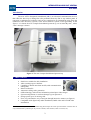
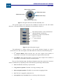
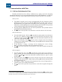
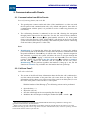
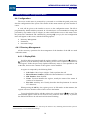
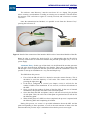
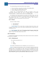
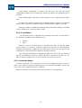
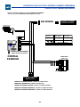
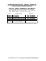
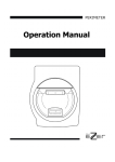
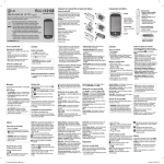
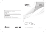
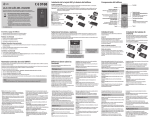
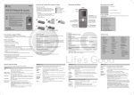
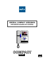
CENTRAL COMPACT INTEGRADA
INTEGRATED GUARD UNIT CENTRAL
HI / 86
02/05
LLAMANDO A:
120506
AUX
5
4
3
2
6
1
7
8
9
0
COMPACT
ENGLISH
HI / 91
12/06
INTEGRATED GUARD UNIT CENTRAL-CENTRAL COMPACT INTEGRADA
Description-Descripción
CENTRAL COMPACT INTEGRADA
INTEGRATED GUARD UNIT CENTRAL
195mm
Vi
HI / 86
-
02/05
B
230mm
D
AUX
5
4
3
2
6
1
7
H
8
9
}
CONEXION CAMARA AUXILIAR* - AUXILIARY CAMERA CONNECTION*
EXTENSION DE LLAMADA ELECTRONICA (SALIDA POLARIZADA) 24V
Electronic call extension (polarized output) 24V
AUX2 SALIDA AUXILIAR 2 (AUX)- OUTPUT AUXILIARY PUSH-BUTTON (AUX)
AUX1 SALIDA AUXILIAR 1 (
)- OUTPUT AUXILIARY PUSH-BUTTON ( )
ALTAVOZ - LOUDSPEAKER
MICROFONO - MICROPHONE
+ POSITIVO - POSITIVE
- NEGATIVO - NEGATIVE
G
LLAMANDO A:
120506
C
E
+
F
A
CAMERA
MODULO DE CONEXIÓN
CONNECTION MODULE
Vo
0
Vi
} SALIDA DE VIDEO - VIDEO OUTPUT
} ENTRADA DE VIDEO - VIDEO INPUT
CONECTOR DE LA CENTRAL COMPACT INTEGRADA
Connector of the INTEGRATED GUARD UNIT CENTRAL
COMUNICACIÓN CON PC
PC´s communication
b
A.
B.
C.
D.
E.
F.
G.
H.
PEANA PARA CENTRAL (OPCIONAL)
CENTRAL BASE (OPTIONAL)
Mango Teléfono de central. Guard unit central phone
Pulsador abrepuertas. Door opener key
Pulsador Autoencendido. Self-starting key
Pulsador auxiliar 1. Auxiliary key 1
Pulsador auxiliar 2. Auxiliary key 2
Pantalla TFT color. TFT colour display
Mensajes de la central en pantalla.
Navegador. Navigator keys
INSTALACIÓN - Installation
15
0m
m
m
0m
15
CAMERA
Módulo de conexión para central
Guard unit module of connection
BW
Vo
-
+
AUX2
AUX1
2º
+
Vo
Vi
}
BUS DE LA INSTALACION
INSTALLATION COMMON WIRES
1º Fijar la plancha a la pared con los tacos y tornillos
suministrados
2º Embornar los cables.
3º Conectar la central con el latiguillo al circuito del
módulo de conexión.
4º Colgar la central en la plancha fijada en la pared
3º
CONECTOR DE LA CENTRAL COMPACT INTEGRADA
Connector of the INTEGRATED GUARD UNIT CENTRAL
1º Fix the bracket to the wall using supplied screws.
2º Connect the wires
3º Connect central's plug to circuit's bracket
4º Plug the central to the bracket.
1
CÁMARA/CAMERA
CAMERA
INTEGRATED GUARD UNIT CENTRAL
User Guide
Introduction
The new AUTA Integrated Switchboard (SB) is an advanced communication device,
that offers the best way to manage the calls performed from any flat or any outdoor panel. It
represents a technological evolution, and can be considered as an intermediate stage from the
traditional video door entry systems, to the newest domotic systems of last generation. In the
figure 1 it is shown the new Compact Switchboard powered up, on its Stand By state1, where
“auta” message is shown.
Figure 1. The new Compact Switchboard powered up.
¾ Main Features
•
•
•
•
•
•
•
•
•
•
Small size, suitable for desk installation.
Able to manage up to 1024 flats.
Capability to install more than one SB, with communication
among then.
Data load from PC.
Automatic calling codes generation.
OSD technology with relevant information printed upon video images.
System configuration via software through a given password.
Storage queue up to 25 missing calls.
New, easy and intuitive way of navigate through interactive menus (see figure 6).
Compatible with digital only audio installations, B&N video and COLOR video
installations.
1
The SB in stand-by mode and the handset hung down keeps the screen powered down. It will be turn on
only if the handset is picked up or any action is made (a call incomes, enter to a menu, etc).
2
INTEGRATED GUARD UNIT CENTRAL
User Guide
Functioning
The new switchboard includes 4 operating modes, that determine the way it reacts to the
incoming calls from the outdoor panels:
•
Standard Mode: The switchboard receives all the incoming calls made from the
panels. If they are not attended during the next 30 seconds, they will be
automatically passed through to the appropriated flat.
•
Direct Mode: All the incoming calls made from the panels will be automatically
passed through to the flats. The switchboard will show on screen information about
the incoming call, but it won’t be able to interfere. If the SB receives a code which
is not stored in its database, it will manage it as “Call to Switchboard” (the
incoming call won’t be passed through to any flat).
•
Not Disturb: It works the same as the Standard Mode, but if the incoming calls are
not attended during the first 30 seconds, they won’t be passed through to the flats.
•
Manager Mode: The switchboard only receives incoming calls from other
switchboards, never from outdoor panels or flats. However it can call the flats, the
rest of the switchboards and/or execute a self-start over the outdoor panels.
This is a special mode that requires to be enabled from the configuration menu
(see chapter 4.4).
To explain the functioning of the switchboard we must differentiate 2 kinds of users. On
one side the guard porter and on the other side the installer or the owner. This one will have an
up to 9 digits password to get access to the configuration menus.
¾ Standard User: The Guard Porter
The guard porter will be able to establish communication with the flats, the outdoor
panels and the switchboards. However, he will have a limited access to the configuration menus.
To perform all its functions, the SB includes a navigator, a special functions keypad and
a numeric keypad.
The numeric keypad is composed by the 10 decimal characters, arranged on a dial form.
It is meanly used to introduce calling codes, improving this way several tasks like calling,
searching within the directory, etc.
The navigator is a very versatile element, capable to accomplish many functions
(moving inside menus, passing through calls, carrying out requests, execute actions, etc).
It is composed by 4 direction keys (Å Æ Ç È) and another one for confirmation (OK).
Functions assigned to each one of them are shown every moment at the bottom of the screen,
and they vary according to the task that it is executing in that moment (calling, conversation,
navigating through menus, etc).
Functions that are carry out by the navigator while the SB remains in Stand By state
(screen switched off or screensaver active), are shown in figure 2.
3
INTEGRATED GUARD UNIT CENTRAL
User Guide
Direct entry to Queue.
Main menu entry.
Main menu entry.
Main menu entry.
Direct entry to Directory.
Figure 2. Navigator functions with SB in Stand By state.
The special keypad is the same that the COMPACT monitor one and with similar
functions. A description about its 4 pushbuttons is shown bellow (figure 3):
Door-Release Button / Call to Switchboard
when the handset is picked up.
Self-Starting / End of Call when the
•
handset is hung up.
•
• 2nd Camera Button.
• Aux Button.
Figure 3. Special functions keypad.
The pushbuttons 2nd Camera and Aux of the special functions keypad, are used to
activate the Aux1 and Aux2 outputs of the SB module of connections in the following way:
•
2nd Camera Button: When pressed once, the Aux1 output of the module of
connections is activated. If it is pressed again, the output will be deactivated.
•
Aux Button: Each time this button is pressed, the Aux2 output of the module of
connections is activated for 100 ms (activation pulse).
There is a blue led (blue lamp), that brings information about the system state, because it
shines in a different way depending on the action the SB is performing in that moment:
•
Off: Switchboard in stand by or powered off.
•
Long and slow sparkles: The SB is receiving or making a call.
•
Short and quick sparkles: The SB is in conversation, engaging the line.
•
On: The line is engaged by another device.
•
One sparkle every 2 seconds: There are missing calls in the queue.
4
INTEGRATED GUARD UNIT CENTRAL
User Guide
1. Communication with Flats.
1.1. Call from Switchboard to Flats:
The SB can initiate the call to a flat by 3 different ways: Typing a call code, navigating
through the Directory or also navigating through the Queue. If the installation is a video one,
the monitor in the flat will get image from the auxiliary camera of the SB, if it is installed.
Call by Code:
•
•
•
The numeric keypad is used to type an appropriated call code (characters will be
displayed on screen in big size), and then OK should be pressed. If the code is in
the SB database, the register that corresponds to the code will appear on screen.
Otherwise, it will be displayed on screen the message NOT FOUND. This operation
can be performed either with the handset picked up or hung up.
Pressing again the OK button the call will be preformed. This operation must be
performed with the handset picked up.
Key Å (Exit) can be pressed at any moment to cancel the numeric call code entry.
Call from Directory:
•
•
•
•
From the Stand By state, if the key È is pressed the system grants access directly to
the “Directory” database. Another way to proceed would be by pressing any of the
central keys of the navigator (Å OK Æ) to enter the main menu, and then select the
“Directory” option pressing OK.
Once in the directory, keys ÇÈ can be used to navigate across the directory
looking for the suitable register. When found, pressing OK with the handset picked
up will perform the call.
If the directory is empty, a message will be displayed on screen (“Empty
Directory”) and no call will be able to be performed to any flat.
Key Å (Exit) can be pressed at any moment to cancel the navigation through the
directory.
Call from Queue:
•
•
•
•
From the Stand By state, if key Ç is pressed the system grants access directly to
queue. Another way to proceed would be by pressing any of the central keys of the
navigator (Å OK Æ) to enter the main menu, and then select the “Queue” option
pressing OK.
Once in the queue, keys ÇÈ can be used to navigate across the list of missing calls
looking for the desired register. When found, pressing OK with the handset picked
up will perform the call.
If the queue is empty, a message will be displayed on the screen (“Empty Queue”)2.
Consult section 4.2. for further information.
Key Å (Exit) can be pressed at any moment to cancel the navigation through the
queue.
Calls stored in the queue can only be deleted if they are manually erased (pressing Æ in “Queue” menu),
or if the call is returned and the conversation is established. If there are more than 25 calls in the queue,
the oldest calls will be removed and replaced by the newest ones.
2
5
INTEGRATED GUARD UNIT CENTRAL
User Guide
In any of the 3 cases, when a call is performed, the following messages may be
displayed on the screen:
•
•
•
•
•
•
When the call is performed, at the bottom left corner of the screen will appear the
message: Calling to.
If the handset is picket up in the flat, the message will change to: Talking.
If the handset is hung up in the SB or in the flat, or if the time for the conversation
overcomes, on top of the screen will appear in capitals and big size, the message:
END OF CALL.
If the called Phone/Monitor doesn’t exist, it’s turned off or it’s damaged, the
message will be: NOT AVAILABLE.
If it is a system with SDL (SB is configured as external), and the SDL is the one
which it is damaged, the message will be: NO REPLY.
If the line is occupied with another conversation (in example, with an internal
panel), the message will be: LINE ENGAGED.
1.2. Call from Flats to Switchboard:
With the handset of the Phone/Monitor in the flat picked up, press the door-release
button (³). The monitor will not have video picture on the screen.
At the switchboard:
•
•
•
•
If data corresponding to the flat is registered in the database of the SB, this one will
ring and it will display this data on the screen. If the guard porter doesn’t attend the
call picking up the handset, it will be stored in the queue. If the guard porter rejects
the call (pressing key 1 without picking up the handset), it will not be added to the
queue.
If the Phone/Monitor that performs the call is not registered in the database, the SB
will ring showing the identification of the Phone/Monitor, and the one of the SDL if
that was the case. This call will not be stored in the queue if it is not attended.
If the switchboard is engaged or powered off, or the guard porter rejects the call, the
Phone/Monitor led will shine with red light and, in systems with SDL, short and
quick beeps will be heard (tones of line engaged).
The switchboard will always receive calls from flats in Standard, Direct and Not
Disturb modes. In Manager mode it can only receive calls from another switchboard
(see section 3).
When the SB receives a call from a flat, the following messages may appear on the
screen:
•
•
•
When the call is received, it will be shown in the left bottom corner of the screen
the message: Request from.
If the guard porter picks up the handset, message will change to: Talking.
If the handset is hung up in the SB or in the flat, or if the time for the conversation
overcomes, on top of the screen will appear in capitals and big size, the message:
END OF CALL.
6
INTEGRATED GUARD UNIT CENTRAL
User Guide
2. Communication with Panels.
2.1. Communication from SB to Panels:
Press self-starting button (1) in the SB:
•
The guard porter connects audio and video (if the installation is a video one) with
the last panel it had communication with, or by default with panel 0. Once there is
communication with the panel, it is possible to use the readdressing function (see
note below).
•
The self-starting function is enhanced in the new SB, allowing the navigation
through panels connected to the same bus. For this, the vertical arrows should be
used to increase È or decrease Ç the panel number (from 0 to 15). If the panel
doesn’t exist, the message “NOT AVAILABLE” will appear on the screen, but the
system will still allow to keep searching, until whatever panel answers connecting
audio and video (if the panel is a video one).
Note:
•
Readdressing is a function that allows the guard porter to connect the outdoor
panel with any flat in the installation. For that, once the SB has communication with
the panel established, if the OK key (it will have the “Change” function assigned at
that moment) is pressed, the system will allow the user to navigate through the
directory (using ÇÈ or typing a valid call code and then OK). Once the correct
register is found, it is possible to pass the call pressing Æ, or perform a consult to
the flat with Å (these two functions will be explained on the next point).
Readdressing can be perform regardless the handset is hung up or not, but the
function of consult is only available once the handset has been picked up.
2.2. Call from Panel3:
Call with a valid code:
•
The screen of the SB will show information about the flat the call is addressed to,
and also about the number of the panel the call comes from (see figure 4). This
information will be shown over a blue screen if the panel is an audio panel, or over
the video of the panel’s camera if this is a video panel.
4
With the handset of the SB hung up the following actions can be performed:
•
•
•
•
Open the door (³).
Reject the call (1).
Pass the call through to the corresponding flat directly (Æ).
Readdress the call and pass it through to another flat (OK + search + Æ).
3
The process explained corresponds to the Standard Mode functioning. Differences among each
operation mode had been described before.
4
When a call is received, if the handset of the SB is picked up, the SB will act the same way as if the
handset was hung up, but it won’t ring. In that case, the self-start button (1) is used to “pick up”, and the
hook switch must be used to reject the call.
7
INTEGRATED GUARD UNIT CENTRAL
User Guide
Picking up the handset the communication starts off, and it is possible to:
•
•
•
•
•
Open the door (³).
Pass the call through to the flat (Æ).
Perform a consult to the flat (Å).
Readdress the call and pass it through to another flat (OK + search + Æ).
Readdress the call and perform a consult to another flat (OK + search + Å).
auta
Cod: 030101
Pedro Martínez
P: 1
1º C
Calling to
(
Å
OK Change
Æ Pass to
Figure 4. Call from panel to a flat.
Call with an invalid code (Call to Switchboard ):
•
Any code typed on the outdoor panel that hasn’t been loaded in the database of the
switchboard will be understood as “Call to Switchboard”:
• On screen the number of the calling panel will be shown and also the
identification of Phone/Monitor 0, and of SDL 0 (see figure 5).
• The call is managed the same way as another one, but it couldn’t be passed
through to a flat directly (using of code 0 is not allowed for phones, monitors or
SDLs). It is necessary to readdress the call to a flat in the database to pass it
through, or to perform a consult.
auta
P: 1
m/t: 0
SDL: 0
Calling to
(
Å
OK Change
Æ
Figure 5. Call from panel with an invalid code (Call to Switchboard).
8
INTEGRATED GUARD UNIT CENTRAL
User Guide
Note:
•
Pass to (Æ): It is used when the guard porter wants to pass the incoming call
through to the flat, without needing to consult before. When the handset is picked
up in the flat, the switchboard will show the message LINE ENGAGED and it
won’t be able to interfere the conversation.
•
Consult (Å): It is used when, either by oneself initiative or explicit instruct from
tenants, the guard porter asks the flat about the convenience of passing the call
through or not. So, after have talked to the outdoor panel, the guard porter contacts
with the flat. At that moment, switchboard and flat have both the same video picture
from the panel’s camera, but audio only between them. If user in the flat decides to
accept the call, he/she should press the door-release key (³) of the Phone/Monitor.
Then conversation will be established between the panel and the flat. The
switchboard will show the message LINE ENGAGED. If user decides to reject the
call, he/she should hang up the handset. After that, the guard porter will can use the
self-start function to talk to the panel again.
9
INTEGRATED GUARD UNIT CENTRAL
User Guide
3. Communication with another SB.
The SB allows keeping communication with other SB in a similar way that it does with
the flats.
3.1. Call to another SB:
It is possible to call to another SB in two different manners: by code or from the missing
calls queue.
Call by Code:
•
•
•
The door-Release key (³) of the SB must be pressed. Then it will appear the
“Calling to Switchboard” menu and the code of the last SB called, or of the last one
a call has been received from will be shown.
The switchboard which is being called is selected using the vertical arrows, to
increase È, or decrease Ç the number of the SB (from 0 to 15). To exit this menu,
the door-release key (³) must be pressed.
To perform the call, pick up the handset and press OK. The call will be performed
in a similar way than if it was a call to a flat.
Call from Queue:
•
•
•
In the missing calls queue are also stored missing calls from other switchboards.
Once in the queue, navigate through the missing calls until find the call from the
switchboard.
To perform the call, just pick up the handset and press OK.
3.2. Call from another SB:
Any switchboard can receive calls from the rest, regardless its operating mode.
The switchboard manages this kind of calls in a similar manner that it does with the
other kinds of calls:
•
•
•
It identifies the switchboard which is calling.
If it doesn’t answer in the first 30 seconds, the call is queued.
Communication between both switchboards is established picking up the
handset.
10
INTEGRATED GUARD UNIT CENTRAL
User Guide
4. Menus.
In the Stand By state, if any of Å OK Æ keys is pressed, the menu shown in figure 6
will appear on the screen. Using ÇÈ and OK keys it is possible to get to any option of this
menu.
auta
Æ
Directory
Queue
Settings
Configuration
Main Menu
( Select
Å Exit
OK Accept
Æ
Figure 6. Switchboard menus.
4.1. Directory:
•
The Directory menu can be also reached directly from the Stand By state pressing
È key. This menu allows navigating through the registers of the database and
calling them picking up the handset and pressing OK.
•
The navigation can be achieved using ÇÈ keys. It is also possible to type a call
code using the numeric keypad and then press OK, to access directly to a known
register (if the code is not in the database, the screen will display the message NOT
FOUND).
4.2. Queue:
•
The Queue menu can also be reached directly from the Stand By state pressing Ç
key.
•
The SB stores up to 25 missing calls. These calls can be from flats or switchboards,
but not from panels. Calls are stored according to the order they have been received,
and they won’t be stored if the calls are from flats or switchboards which have
already missing calls included in the queue. If there are more than 25 calls in the
queue, the oldest calls will be removed and replaced by the newest ones.
•
If there isn’t any call stored in the queue, the screen will display the message
“Empty Queue”. The SB will keep the message for 5 seconds and then it will return
to the main menu.
•
The SB shows on screen data corresponding to the flat or switchboard which the
call came from, in a similar manner as they are shown at the Directory. It also
shows in the right side, the order the call has been stored and the whole of calls
queued (see figure 7).
11
INTEGRATED GUARD UNIT CENTRAL
User Guide
•
Calls stored in the queue can only be deleted if they are manually erased (pressing
Æ), or if a call is returned and the conversation is established (if it is not, the call
will remain queued). Once all the calls have been erased, the screen will show that
the queue is empty and the switchboard will return to the main menu.
auta
Cod: 0 00025
Enrique Simon
1/2
2º izda
Queue
( Navigate
Å Exit
OK Call
Æ Erase
Figure 7. Example with 2 calls stored in the queue.
4.3. Settings:
This menu allows adjusting settings related to the manner the SB operates according to the
user preferences.
4.3.1. Operating Mode:
Operating modes determines the way the SB reacts to the incoming calls from the
outdoor panels:
•
Standard Mode: The switchboard receives all the incoming calls made from the
panels. If they are not attended during the next 30 seconds, they will be
automatically passed through to the appropriated flat.
•
Direct Mode: All the incoming calls made from the panels will be automatically
passed through to the flats. The switchboard will show on screen information about
the incoming call, but it won’t be able to interfere. If the SB receives a non-stored
code in its database, it will manage it as “Call to Switchboard” (the incoming call
won’t be passed through to any flat).
•
Not Disturb: It works the same way as the Standard Mode, but if the incoming
calls are not attended during the first 30 seconds, they won’t be passed through to
the flats.
•
Manager Mode: The switchboard only receives incoming calls from other
switchboards, never from outdoor panels or flats. However it can call the flats, the
rest of the switchboards and/or execute a self-start over the outdoor panels5.
This is a special mode that requires to be enabled from the configuration menu
(see chapter 4.4).
5
Only over panels with this feature enabled. See panel manual.
12
INTEGRATED GUARD UNIT CENTRAL
User Guide
Available operating modes are shown on the screen. Current operating mode is also
displayed on the bottom of the screen.
To change the operating mode, use ÇÈ keys and confirm pressing OK.
To exit from this menu, press Å.
4.3.2. Ringtone:
The warning ringtones, that the switchboard generates when it receives a call, can be
configured in this menu. Ringtones are defined by three parameters:
•
•
•
Type: There are 8 different kinds of ringtones.
Number of Ringtones: Times the ringtone is repeated. From 0 (mute) to 4.
Volume: There are 3 volume levels.
The value of these settings can be modified through Å Æ keys. If OK key is
pressed, a sample ringtone will be generated with the current settings.
To exit from this menu, choose the option “Back” and confirm with OK.
4.3.3. Audio:
The parameters of audio input and output can be modified in a similar way that
in the previous settings, using Å Æ keys.
To exit from this menu, choose the option “Back” and confirm with OK.
13
INTEGRATED GUARD UNIT CENTRAL
User Guide
¾ Owner or Installer: Configuration Menu.
4.4. Configuration:
The access to this menu is protected by a password to avoid that the guard porter may
alter the configuration of the system. The content of this menu must be up to the installer or
owner.
A code will be given to the installer to access to the configuration menu. The SB is
programmed by default with the password ‘9’. Nevertheless it is recommended to change the
password by any number of up to 9 digits, in order to difficult the access to this menu. Once
the password is introduced and confirmed by pressing OK (Accept), the real configuration
menu will appear on the screen, with the following options6:
•
•
•
Directory Management.
Parameters.
Password Change.
4.4.1. Directory Management:
All the necessary operations for the management of the database of the SB are made
within this menu.
4.4.1.1. Display/Edit:
It will be able to navigate though the registers with the vertical arrows È (advance),
Ç (go back) as in the Directory menu, but having access to the complete information of
each register. Unlike the previously explained Directory menu, it is not possible to call
to the flats, however the contents of the registers can be modified.
A register is composed by the following fields:
•
•
•
•
•
Call Code: Code of up to 6 digits. Used to perform the call.
Phone/Monitor Number: Number the Phone/Monitor is coded with.
SDL Number: Same for SDL.
Name: Text that identifies the register, usually the name of the tenant. It
consists of 16 characters.
Flat Info: Auxiliary text. Usually describes the flat placement. It consists
of 7 characters.
When pressing the OK key, the register goes to its Edit mode. At that moment, the
register will move from the centre of the screen to the bottom.
To go from field to field to edit the register, the vertical arrows ÇÈ are used. The
selected field appears stood out on screen at every moment. If the OK key is pressed,
the field will be able to be edit and it will be shown blinking.
6
In the left bottom corner of the screen it will always be shown a text, indicating the menu the system is
at that moment, to avoid misunderstandings.
14
INTEGRATED GUARD UNIT CENTRAL
User Guide
The first 3 fields are numerical and they are modified using the numerical keys of
the keypad. Name and Flat Info fields are textual fields, and they are modified with the
character set that appears on the screen during their edition. In order to move through
the character set, the keys of the navigator must be used. To leave the character set,
symbol (right bottom corner) must be selected.
To leave the edition of a register the left arrow Å key must be pressed, without any
field in edit mode.
4.4.1.2. Add:
Registers can be added to the directory in 3 different ways:
•
•
•
Manual Entry.
Remote Entry.
Automatic Entry.
Manual Entry: It creates a register with initial values and it shows it on the screen
to its edition, the way explained previously.
Remote Entry: With this method the registers are loaded from a PC. This way, it is
possible to load complex directories really fast.
Before proceeding to load the database of the SB it is recommended to have it
completely empty, in order to avoid confusions between coincident codes. To erase the
directory see chapter 4.4.1.3.
To use the remote entry from PC it is necessary to have the auta connection kit.
This kit includes the software “auta Directory” and an interface for RS232 serial port.
Figure 8. Auta Directory v1.0 software.
The interface should be connected for one side to a RS232 port (see figure 9). The
other side (plug) should be inserted into the connector CON3 placed in the module of
connections of the switchboard (see detail in figure 9).
Once the interface is correctly connected, the SB must be plugged to the module of
connections and then get into “Remote Entry”. At that moment, the SB will wait to
receive data.
15
INTEGRATED GUARD UNIT CENTRAL
User Guide
The software “auta Directory” must be run from a PC or a laptop. The program
allows creating a new database or loading an existing one to transmit it. The SB shows
the message “OK” each time a register is correctly received, and it increases a counter
on screen.
Once the transmission has finished, it is possible to exit from the “Remote Entry”
pressing the left arrow Å.
Figure 9. Detail of the connection of the interface RS232 to the Connections Module of the SB.
Note: In order to perform the load from PC it is indispensable that the SB will be
correctly connected to its connections module and powered up through it, by a 24 V dc
power supply.
Automatic Entry: In this type of data load, it is the SB itself the one that generates
the call codes from the data facilitated by the installer. These data is introduced to the
SB through a series of questions that the system asks about the installation. Thus it is
possible to start up an installation in a very fast and simple way.
The SB follows this process:
•
•
•
•
•
First of all, the SB will ask if it is desired to erase the current directory. This is
advisable to avoid the duplicity of call codes. The erasure can be avoided
pressing the right arrow Æ.
If the SB is configured as external (see chapter 4.4.2.2) it will ask for the
number of SDLs of the installation. If it is internal, it will omit all reference to
the SDL.
Next, it will ask the number of plants of the first SDL. In the case of internal
installations, the question will refer to the total of the plants.
Once data about the SDL and plants is had, it will ask successively for the flats
of each plant. Then, the call codes of that plant are generated and it will ask for
the following plant.
When all the plants of a SDL have been completed, the process is repeated with
the following SDL until completing all of them.
During this process, on screen it is provided information about the SDL and the
plant corresponding to these questions, as well as the total amounts of them. Also the
data introduced in previous steps is remembered to make the process more agile.
16
INTEGRATED GUARD UNIT CENTRAL
User Guide
The automatically generated codes follow a logic sequence:
•
•
•
The two first digits correspond to the number of the building (SDL).
The two digits in the middle indicate the plant.
The two last digits represent the flat itself.
Suitable codes of Telephone/Monitor and SDL are assigned to each of the
automatically generated register. The codes of Telephone/Monitor are generated
correlatively from “1”, and renew their account for each building (SDL).
The Automatic Entry doesn't generate any content in the fields “Name” and “Flat
Info”. After the process has finished, it is advisable entering to “Display/Edit” to review
the generated codes and, if it is desired, edit the registers. When entering to
“Display/Edit” option, the last generated code will be shown.
4.4.1.3. Erase:
There are 2 kinds of erasure:
•
•
Selected Register.
Entire Directory.
Selected Register: This option allows navigating through the directory and
erasing the register shown on the screen. Before erasing the register, the SB will ask for
confirmation to do it.
Entire Directory: This way, all the registers in the directory are erased. In this
process the switchboard also asks for confirmation before continuing. During the
process a progress bar will be shown on the screen.
4.4.2. Parameters:
In this menu, the parameters that identify the SB, and those that describe the installation
of the system, are configured.
4.4.2.1. Switchboard:
The switchboard parameters are 3:
•
•
•
ID.
Status.
Manager.
ID: Number of identification of the switchboard. It can vary from 0 to 15.
Status: It configures the SB as Master or Slave. The Master switchboard defines the
operating mode of the installation. In other words, all the switchboards will work
according to their own operating mode, but it is the Master switchboard the one that
determines if the calls must directly be passed (Direct Mode) or never arrive to the flat
(Not Disturb Mode). Anyway, if any switchboard takes care of a call and decides to
make a consult or to pass it, it will be able to do it without any restriction.
17
INTEGRATED GUARD UNIT CENTRAL
User Guide
If the Master switchboard is switched off, the Slave one with the lowest
identification number (ID) will temporally assume the Master role, performing all its
functions.
Only the Master SB (or the Slave one that replaces it if it is switched off) can queue
calls.
For that reason, if a SB is going to work in Manager Mode, it mustn’t be declared as
Master, and it is advisable to make its number of identification as higher as possible.
Manager: Enables or disables the Manager Mode, that means making it available
or not available in the “Operating Mode” menu.
4.4.2.2. Installation:
The SB needs to have configured some parameters that allow it to know how to
act inside the installation. These parameters are:
•
•
Pull-Up.
Type.
Pull-Up: It can be connected (ON) or disconnected (OFF). So that the digital
system works, it is necessary a Pull-Up connected in the line of communications.
Normally, this Pull-Up is supplied by an outdoor panel. If there isn’t any panel in the
installation, it is necessary that one SB has its Pull-Up connected.
Type: This parameter allows configuring the SB as External or Internal, based on
the type of installation in which it is wired. If the SB is connected to terminals “X” of a
SDL, it must be configured as external. In another case it must be internal.
4.4.3. Password Change:
It allows introducing a new password to access to the configuration menu, of up to 9
digits. At the moment a password (different from 0) is introduced and OK is pressed, the
access code to the configuration menu is modified.
Note: It is advisable to write down the new key in order to avoid forgetting it.
18
INTEGRATED GUARD UNIT CENTRAL-CENTRAL COMPACT INTEGRADA
Installation schema - Esquema de instalación
Portero electrónico digital con central COMPACT INTEGRADA.
Door entry system with INTEGRATED COMPACT guard unit central.
ACCESOS INTERIORES
INTERIOR ACCESSES
BUS GENERAL
-
CÁMARA AUXILIAR
AUXILIARY CAMERA
CAMERA
Secciones de hilos
Wiring sections
Vi
-
(+), (-), R, C
+
CAMERA
HI / 86
02/05
Coaxial
+
LLAMANDO A:
120506
Hasta 100 m.
UP to 100 m.
Hasta 200 m.
UP to 200 m.
1 mm²
2 mm²
0.5 mm²
1 mm²
Tipo/Type RG-59 75
AUX
5
4
3
2
6
Vo
1
7
-
8
9
0
Vi
CENTRAL DE CONSERJERÍA
DIGITAL GUARD UNIT CENTRAL
CENTRAL
EXTERIOR
+ +
ALIMENTADOR
POWER SUPPLY
R
C
220V
BW
RED/NET
220Vac
ACCESO PRINCIPAL
MAIN ACCESS
MÓDULO DE CONTROL DIGITAL / MODULE OF CONTROL DIGITAL
MÓDULO DE CONTROL SDL / MODULE OF CONTROL SDL
MÓDULO DE CONTROL TECLADO / MODULE OF CONTROL KEYBOARD
MÓDULO DE CONTROL DECORPLUS / MODULE OF CONTROL DECORPLUS
MÓDULO DE CONTROL DIRECTORIO / MODULE OF CONTROL DIRECTORY
19
ATF-98
INTEGRATED GUARD UNIT CENTRAL-CENTRAL COMPACT INTEGRADA
Installation schema - Esquema de instalación
4.2.- Videoportero electrónico digital con central COMPACT INTEGRADA.
Digital video door entry system with INTEGRATED COMPACT guard unit central.
COAX
ACCESOS INTERIORES
INTERIOR ACCESSES
BUS GENERAL
CÁMARA AUXILIAR
AUXILIARY CAMERA
CAMERA
Secciones de hilos
Wiring sections
Vi
-
(+), (-), R, C
+
CAMERA
BW
HI / 86
02/05
Coaxial
+
LLAMANDO A:
120506
Hasta 100 m.
UP to 100 m.
Hasta 200 m.
UP to 200 m.
1 mm²
2 mm²
0.5 mm²
1 mm²
Tipo/Type RG-59 75
AUX
5
4
3
2
6
Vo
1
7
-
8
9
0
Vi
CENTRAL DE CONSERJERÍA
DIGITAL GUARD UNIT CENTRAL
CENTRAL
EXTERIOR
+ +
ALIMENTADOR
POWER SUPPLY
220V
R
C
RED/NET
220Vac
- Vo
b
ACCESO PRINCIPAL
MAIN ACCESS
MÓDULO DE CONTROL DIGITAL / MODULE OF CONTROL DIGITAL
MÓDULO DE CONTROL SDL / MODULE OF CONTROL SDL
MÓDULO DE CONTROL TECLADO / MODULE OF CONTROL KEYBOARD
MÓDULO DE CONTROL DECORPLUS / MODULE OF CONTROL DECORPLUS
MÓDULO DE CONTROL DIRECTORIO / MODULE OF CONTROL DIRECTORY
20
COMPATIBILIDAD CENTRAL COMPACT INTEGRADA
INTEGRATED SWITCHBOARD COMPATIBILITY
LA CENTRAL COMPACT INTEGRADA ES COMPATIBLE CON
LAS SIGUIENTES VERSIONES DE MODULO DE CONTROL:
THE INTEGRATED GUARD UNIT CENTRAL IS COMPATIBLE
WITH THE FOLLOWING MODULES OF CONTROL:
REF:
600005
600006
600007
730121
600009
600010
600011
DESCRIPCION
M.C. DIGITAL
M.C. TECLADO
M.C. SDL
SDL
M.C. DIGITAL DECORPLUS
M.C. PLACA DIRECTORIO
M.C. VISUAL TECH 5H
SELECTOR DIGITAL de LINEAS
VERSION
1.4 o POSTERIOR
1.8 o POSTERIOR
1.5 o POSTERIOR
1.1 o POSTERIOR
2.0 o POSTERIOR
2.0 o POSTERIOR
NO ES COMPATIBLE
auta comunicaciones s.l. POL. IND. EL OLIVERAL - CALLE C , 46394 RIBARROJA DEL TURIA (VALENCIA)
TFNO. +34 96 164 30 20 - FAX. +34 96 166 52 86 E-MAIL: [email protected] HTTP://WWW.AUTA.ES