1
August 2010
Sirius SAT
Built-in User Modules
R/1 – RP/1 – RS – RSP – R2Z
Installation and Operating Manual
Working towards
a cleaner future
heating specialists
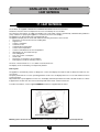
TO THE OWNER OF THIS POTTERTON COMMERCIAL APPLIANCE
We are confident your new POTTERTON COMMERCIAL appliance will meet all your requirements.
All POTTERTON COMMERCIAL products have been designed to give you what you are looking for: good
performance combined with simple and rational use.
Please do not put away this booklet without reading it first as it contains some useful information which will
help you to operate your appliance correctly and efficiently.
Caution: Do not leave any packaging (plastic bags, polystyrene, etc.) within reach of children, as it is a potential source of danger.
POTTERTON COMMERCIAL S.p.A. declares that these models of boiler bear the
CE mark in compliance with the basic requirements of the following Directives:
- Gas Directive 90/396/EEC
- Efficiency Directive 92/42/EEC
- Electromagnetic Compatibility Directive 2004/108/EEC
- Low Voltage Directive 2006/95/EC
The instructions shall state the substance of the following:
This appliance is not intended for use by persons (including children) with reduced physical, sensory or mental
capabilities, or lack of experience and knowledge, unless they have been given supervision or instruction concerning use of the appliance by a person responsible for their safety.
Children should be supervised to ensure that they do not play with the appliance.
INSTALLATION AND OPERATING MANUAL
2
912.808.1 - IT
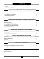
CONTENTS
1. Description
2. Instructions prior to installation
4
4
INSTALLATION INSTRUCTIONS: HYDRAULIC CONNECTIONS
3. Centralised system requirements
4. Mounting the template casing
5. Mounting the appliance
6. Flow rate/pressure drop characteristics
7. Output/pump head performance
8. Domestic hot water production
9. Domestic water meter
5
11
12
13
15
16
16
INSTALLATION INSTRUCTIONS: ELECTRICAL CONNECTIONS
10. Electrical connections
11. Wiring diagrams
12. Connecting the ambient thermostat
13. Connecting the floor overheating thermostat
14. Installing and connecting the external probe
15. Connecting the ECOCRONO climate controller
16. Adjusting the electronic board
19
20
25
26
27
28
28
INSTALLATION INSTRUCTIONS: HEAT METERING
17. Heat metering
18. Automatic radio wave reading system
32
33
START-UP AND OPERATING INSTRUCTIONS
19. Filling the system
20. Air vent and pump release
21. Start-up
22. Electronic board signals
37
37
38
39
MAINTENANCE INSTRUCTIONS
23. Dismounting/ Cleaning the domestic hot water heat exchanger
24. Cleaning the central heating inlet filter
25. Cleaning the cold water filter
41
42
43
26. Circuit diagram
27. Disposal
28. Technical specifications
44
50
50
INSTALLATION AND OPERATING MANUAL
3
912.808.1 - IT
FOREWORD
The SIRIUS SAT user modules make it possible to independently manage heating requirements in centralised systems,
me- ter the heat distributed to each unit (flat or independently managed area) and transmit heat consumption data via
radio.
The following notes and instructions are addressed to fitters to allow them to carry out trouble-free installation. The operating instructions are contained in the “Start-up and operating instructions” section of this manual.
ATTENTION:
-
Do not leave any packaging (plastic bags, polystyrene, etc.) within the reach of children as they are a potential
source of danger.
The appliance must be housed in the template casing supplied in a separate pack.
Flush the Domestic Hot Water circuit prior to use.
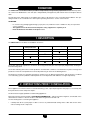
1. DESCRIPTION
The SIRIUS SAT user modules are available in 6 versions:
SIRIUS SAT
Instantaneous hot
water production
Dual zone
Circulation pump
CASING kit
SIRIUS SAT R/1
-
-
-
L = 600
SIRIUS SAT RP/1
-
-
L = 600
SIRIUS SAT R2Z
-
●
●
●
SIRIUS SAT RS
●
●
●
-
-
L = 600
-
●
●
L = 600
SIRIUS SAT RSP
SIRIUS SAT RS2Z
●
L = 800
L = 800
The models with pump separate the circuit from the head generated by the column pump by independently feeding the
internal heating circuit.
The models featuring domestic hot water production are fitted with a stainless steel instantaneous plate exchanger and
produce hot water at a temperature that can be adjusted using an electronic modulating device.
The dual-zone models can separately manage two heating zones at different temperatures and are ideal for combined
cen- tral heating systems (underfloor radiant panels at a low temperature with radiators at a high temperature).
2. INSTRUCTIONS PRIOR TO INSTALLATION
These appliances must be inserted in a centralised heating system, especially designed for this purpose, consistently with
their performance levels and power outputs.
The fitter must be legally qualified to install heating appliances.
Initial start-up must be performed by a POTTERTON COMMERCIAL - authorised Service Engineer, as indicated on the
attached sheet. Failure to observe the above will render the guarantee null and void.
Do the following before connecting the appliance:
r $BSFGVMMZáVTIBMMUIFTZTUFNQJQFTJOPSEFSUPSFNPWFBOZSFTJEVBMUISFBEDVUUJOHTXBSGTPMEFSBOETPMWFOUTJOUIF
various heating circuit components.
INSTALLATION AND OPERATING MANUAL
4
912.808.1 - IT
INSTALLATION INSTRUCTIONS:
HYDRAULIC CONNECTIONS
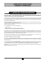
3. CENTRALISED SYSTEM REQUIREMENTS
Some general indications concerning the installation of the centralised heating system are shown below. For
these types of plants, a cutting-edge bespoke design is always necessary in order to ensure ideal conditions of
comfort, save energy and reduce the environmental impact.
Install the boilers in a cascade arrangement (preferably condensation boilers with low pollutant emissions) of a suitable
size to optimise plant performance according to seasonal loads, user demand and Domestic Hot Water demand peaks.
The maximum installed power must consider a simultaneous use factor so as not to oversize the generator and consequently reduce operating efficiency.
The centralised plant must service the various floors of the building by means of columns positioned in the stairwells or
in utility rooms which should preferably be inspectable.
A hydraulic separator should always be fitted downline from the heat generator as this separates circulation in the generator from circulation in the columns.
The centralised plant must have the following features:
r "VUPNBUJDàMMJOH
r &YQBOTJPOTZTUFNTJ[FEBDDPSEJOHUPUPUBMQMBOUDBQBDJUZ
r 0WFSQSFTTVSFTBGFUZWBMWFTJ[FEBDDPSEJOHUPDVSSFOUMFHJTMBUJPO
Each suitably sized column must be fitted with a circulator (preferably at variable speed depending on the demand of the
modules), on/off valves and a dynamic balancing valve. Automatic air vents must be installed at the top of the columns.
The inlet sections must have the same pressure drop in order to allow the system to balance feed to all the user systems.
The recommended typology is three columns with a reverse return line.
Modules with Domestic Hot Water production require an appropriate centralised plant capacity so as to produce a thermal mass that can limit the instantaneous operation of the generator (column oversizing).
The columns and manifolds must be well lagged.
For models without pump (R/1 – RS), the heating circuit pressure drops downline from the user module (R = 0.3 KPa/m per
linear metre + local pressure drops) and the pressure drop of the module itself must also be considered when calculating
the pressure drops.
For models with pump (RP/1 – RSP – R2Z – RS2Z) make sure that the circuit pressure drops downline from the module (R
= 0,3 KPa/m per linear metre + local leaks) are compatible with the pump supplied together with the module. In this case,
the column pump must offset the circuit pressure drops upline from the module (a residue head is acceptable).
SIRIUS SAT user modules are fitted with an automatic by-pass valve which opens the circulation circuit when the pressure
drops exceed 60 kPa (inlet valve closed).
INSTALLATION AND OPERATING MANUAL
5
912.808.1 - IT
SIRIUS SAT
CENTRAL HEATING
SIRIUS SAT
0903_2001 / CR_0034
DOMESTIC HOT WATER
CENTRAL HEATING
DOMESTIC HOT WATER
SIRIUS SAT
CENTRAL HEATING
DOMESTIC HOT WATER
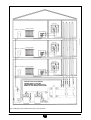
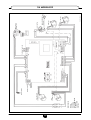
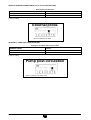
HEATING PLANT WITH BOILERS
CONNECTED IN A CASCADE
ARRANGEMENT AND CENTRALISED
DOMESTIC HOT WATER PRODUCTION
Figure 1A: Diagram of plant: centralised domestic hot water production
INSTALLATION AND OPERATING MANUAL
6
912.808.1 - IT
SIRIUS SAT
CENTRAL HEATING
SIRIUS SAT
0903_2002 / CR_0012
DOMESTIC HOT WATER
CENTRAL HEATING
DOMESTIC HOT WATER
SIRIUS SAT
CENTRAL HEATING
DOMESTIC HOT WATER
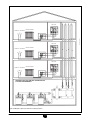
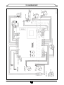
HEATING PLANT WITH BOILERS CONNECTED IN A
CASCADE ARRANGEMENT
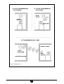
Figure 1B: Diagram of plant: local domestic hot water production
INSTALLATION AND OPERATING MANUAL
7
912.808.1 - IT
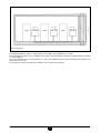
HOME A
SIRIUS SAT
HOME B
SIRIUS SAT
HOME C
0903_2003p / CR_0013
SIRIUS SAT
Figure 1C: Floor layout
The indicative diagram in figure 1c only illustrates the feed pipes of the individual user modules.
The heating plant inside the zone controlled by the module must be realised by feeding the heating elements according
to normal methods.
For models with domestic hot water production, a stub of the hydraulic network must be attached to the Domestic Hot
Water inlet connector ES.
The domestic hot water outlet US must feed all the user hot water take-off points.
INSTALLATION AND OPERATING MANUAL
8
912.808.1 - IT
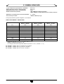
3.1 GENERAL SIZING DATA
- Campo temperatura acqua impianto centralizzato:
- Water temperature range in centralised plant:
- Maximum water pressure in centralised plant:
- Module feed flow rate (nominal):
60 - 75 °C
60 - 75 °C
4 bar
700 ÷ 1000 l/h for heating only models
1000 ÷ 1500 l/h for models with domestic hot water production
- Maximum recommended speed of heat transfer fluid:
- Pressure drop in module:
1 ÷ 1.5 m/s
20 KPa at 700 l/h (see § 6)
Some purely indicative general sizing data is shown below:
TABLE: HEAT DEMAND – HEATED AREA
Area to heat
(m2)
Heat demand (*)
With F1 = 20 W/m3
(kW)
Heat demand (*)
With F2 = 30 W/m3
(kW)
Heat demand (*)
With F3 = 45 W/m3
(kW)
60
3,6
5,4
8,1
70
4,2
6,3
9,5
80
4,8
7,2
10,8
90
5,4
8,1
12,2
100
6,0
9
13,5
110
6,6
9,9
14,9
120
7,2
10,8
16,2
130
7,8
11,7
17,6
140
8,4
12,6
18,9
150
9,0
13,5
20,3
(*) Volumetric heat load “F”: 20 - 30 - 45 W/m3 with ∆t = 25 K;
Height of volume to be heated = 3 m
∆t = internal and external temperature difference (internal T = 20 °C, external = - 5°C)
F1 = 20 W/m3 buildings with an excellent level of insulation
F2 = 30 W/m3 buildings with an good level of insulation
F3 = 45 W/m3 buildings with an low level of insulation
INSTALLATION AND OPERATING MANUAL
9
912.808.1 - IT
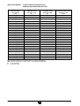
TABLE: HEAT DEMAND – FLOW OF WATER IN HEATING CIRCUIT
DOMESTIC HOT WATER TAKE-OFF FLOW
Heating
domestic water
heat capacity
(kW)
∆T1
∆T2
R
S
Flow rate
of Heating circuit
with ∆T1 = 15 K
(l/h)
Flow rate
of Heating circuit
with ∆T1 = 20 K
(l/h)
Flow rate
of domestic water circuit
with ∆T2 = 35 K
(l/min)
7 (R)
401
301
2,9
8 (R)
459
344
3,3
9 (R)
516
387
3,7
10 (R)
573
430
4,1
11 (R)
631
473
4,5
12 (R)
688
516
4,9
13 (R)
745
559
5,3
14 (R)
803
602
5,7
15 (RS)
860
645
6,1
16 (RS)
917
688
6,6
17 (RS)
975
731
7,0
18 (RS)
1032
774
7,4
19 (RS)
1089
817
7,8
20 (RS)
1147
860
8,2
21 (S)
1204
903
8,6
22 (S)
1261
946
9,0
23 (S)
1319
989
9,4
24 (S)
1376
1032
9,8
25 (S)
1433
1075
10,2
26 (S)
1491
1118
10,6
27 (S)
1548
1161
11,1
28 (S)
1605
1204
11,5
29 (S)
1663
1247
11,9
30 (S)
1720
1290
12,3
= Difference between User Module Delivery – Return Temperature
= Difference between hot water outlet – cold water inlet temperature
= central heating
= domestic water
INSTALLATION AND OPERATING MANUAL
10
912.808.1 - IT
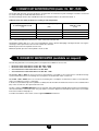
4. MOUNTING THE TEMPLATE CASING
CASING/TEMPLATE MODEL
WIDTH
SIRIUS SAT MODELS
SINGLE-ZONE SIRIUS SAT KIT
l = 600 mm
R/1 - RP/1 - RS - RSP
DUAL-ZONE SIRIUS SAT KIT
l = 800 mm
R2Z - R2Z
Install the SIRIUS SAT model inside the casing/template supplied in a separate pack.
Make sure the template casing model is correct (L= 600 or L=800 mm).
Fit the template/casing in a niche in the wall made for this purpose (dimensions indicated in figures 2 and 3) and secure it
with the relative lateral bent pins. Make sure the installation allows easy access for maintenance.
Remove the door and white frame and put back after installation (make sure the casing accessories also include the key
for opening the door).
The frame can be depth-adjusted by using the 4 butterfly nuts located in the side guides. It is therefore possible to fit the
frame flush against the plaster and remove it when painting the wall.
SINGLE-ZONE SIRIUS SAT KIT
0607_0201 / CR_0029
Assemble the system starting from the position of the water connectors on the lower crossbar of the template (recessed
into the casing by 30 cm). Install the casing in the stairwell outside the apartment to heat.
L = 600
H = 650
P = 150
L = 800
H = 750
P = 150
DUAL-ZONE LUNA SAT KIT
Figure 2: Casing/template
INSTALLATION AND OPERATING MANUAL
11
912.808.1 - IT
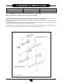
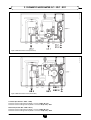
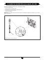
5. MOUNTING THE APPLIANCE
0902_0805 / CR_0018
0902_0804 / CR_0017
After completing the masonry work, hook the SIRIUS SAT module onto the casing/template and make the hydraulic connec- tions using the supplied telescopic connections (see figure 3).
Before fixing the module, drill holes in the rear wall for the Ø 10mm expansion grips (use the holes in the casing/template
as a guide). Then secure the module with the supplied screws.
Fixing slots
Casing P 150
Fixing slots
Seats for screws
Casing P 150
Casing H 750
Connector items 30
Connector items 30
Casing H 650
Seats for screws
Casing L 600
Casing L 800
Figure 3 A: Connectors and sizes of SIRIUS SAT R/1 – RP/1
– RS – RSP
Figure 3 B: Connectors and sizes of SIRIUS SAT R2Z – RS2Z
Key
CONNECTIONS TO CENTRALISED PLANT
IP: primary inlet from centralised plant G 3 ⁄ 4” M
UP: primary outlet from centralised plant G 3 ⁄ 4” M
HEATING PLANT CONNECTIONS FOR SINGLE-ZONE MODELS
MR: G 3/4” M heating plant delivery
RR: G 3/4” M heating plant return
HEATING PLANT CONNECTIONS FOR DUAL-ZONE MODELS
MRAT: high temperature plant delivery G 3 ⁄ 4” M (Models R2Z and RS2Z)
MRBT: low temperature plant delivery G 3 ⁄ 4” M (Models R2Z and RS2Z)
RRAT: high temperature plant return G 3 ⁄ 4” M (Models R2Z and RS2Z)
RRBT: low temperature plant return G 3 ⁄ 4” M (Models R2Z and RS2Z)
CONNECTIONS TO DOMESTIC WATER PLANT
ES (*): domestic water inlet G 1/2” M (Models RS, RSP, RS2Z)
US: domestic hot water outlet G 1/2” M (Models RS, RSP, RS2Z)
DOMESTIC WATER METER CONNECTIONS
ESC1 (*): domestic water inlet to meter G 3/4” M
ESC2 (*): domestic water inlet to second meter G3/4’’ M (Models R, RP, R2Z)
(*) If the meter is installed to measure domestic water consumption (accessory supplied on request), move the domestic water inlet to the
hydraulic connector ESC1 (or ESC2)
INSTALLATION AND OPERATING MANUAL
12
912.808.1 - IT
Items in the SIRIUS SAT user module pack.
r
r
r
r
r
r
r
r
r
4DSFXTBOEFYQBOTJPOHSJQTNN
5BQ(cuVTFSNPEVMFJOMFU
5BQ(cuSFUVSOUPDFOUSBMJTFEQMBOU
5BQ(cuIFBUJOHQMBOUEFMJWFSZGPSEVBM[POFNPEFMT
5BQ(cuIFBUJOHQMBOUSFUVSOGPSEVBM[POFNPEFMT
5BQ(cuEPNFTUJDXBUFSJOMFUNPEFMTXJUIEPNFTUJDIPUXBUFSQSPEVDUJPO
5BQ(cuEPNFTUJDIPUXBUFSPVUMFUNPEFMTXJUIEPNFTUJDIPUXBUFSQSPEVDUJPO
4FBMT
5FMFTDPQJDKPJOUT
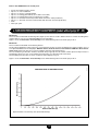
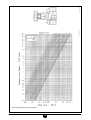
6. FLOW RATE/PRESSURE DROP CHARACTERISTICS (models without pump: R/1 – RS)
Models R/1
These models are fitted with a balancing valve (figure 5). This device is used to balance the flow of water circulating in the
single module in case of non-optimal distribution in the inlet pipes.
Figure 4 shows the Flow Rate – Pressure Drop curve with balancing valve in the wide open position.
Models RS
These models are fitted with two balancing devices.
The first device (balancing valve: Figure 5) is used to balance the flow of water circulating in the single module in case of
non-optimal distribution in the inlet pipes. With this device, the flow rate must not fall below 1000 l/h in the domestic
water mode (lower flow rates do not assure sufficient domestic water performance).
The second device (positioned in the brass hydraulic body: Figure 6) must be used if a further pressure drop increase is
required (this device only acts on the heating circuit and does not affect domestic water flow).
The circulating flow rate value is shown on the heat meter display (see §17).
PRESSURE DROP [kPa]
PRESSURE DROP IN HEATING CIRCUIT
0902_0806
Figure 4 shows the Flow Rate – Pressure Drop curve with balancing valve in the wide open position.
WATER FLOW RATE (l/h)
Figure 4: Flow Rate – Pressure Drop curves (models without Pump)
INSTALLATION AND OPERATING MANUAL
13
912.808.1 - IT
0807_3103 / CR_0185
0807_3104 / D_2151
Figure 5: Balancing valve (models without Pump)
INSTALLATION AND OPERATING MANUAL
14
912.808.1 - IT
0607_0203 / CR_0030
balancing device
Figure 6: balancing device (models RS)
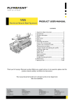
7. OUTPUT/PUMP HEAD PERFORMANCE (only for models with pump: RP/1 – RSP – R2Z - RS2Z)
These models are fitted with a circulation pump.
This silent-running high-head pump is suitable for use on any type of heating system.
The pump, mounted inside the appliance, is fitted out for operation at maximum speed (III). Speed I should not be used
as flow rate/head performance does not satisfy normal operating conditions.
make sure the circuit pressure drops downline from the module are compatible with the supplied pump. In this case, the
column pump must only offset the circuit pressure losses upline from the module (a residue head is acceptable).
The circulating flow rate value is shown on the heat meter display (see §17).
HEAD (KPa]
HEATING CIRCUIT PUMP HEAD
0902_0807
A device for balancing the load circulating in the heating plant is located in the brass body of the hydraulic assembly (figure 6). For these models, check that the lever of this device is wide open.
SPEED III
SPEED II
SPEED I
WATER FLOW RATE (l/h)
Figure 7: Flow Rate - Pump Head curves (models with Pump)
INSTALLATION AND OPERATING MANUAL
15
912.808.1 - IT
8. DOMESTIC HOT WATER PRODUCTION (models : RS – RSP – RS2Z)
The models with domestic hot water production are fitted with an instantaneous plate exchanger in stainless steel sized
for a heat exchange of 35 kW with inlet water at 75 °C.
The heat exchange surface offers suitable domestic hot water performance also with water at 60 °C.
Table: Domestic hot water production according to inlet temperature
Temperature of water
in centralised plant circuit
(°C)
Heat exchange capacity
(kW)
Domestic water flow rate
with ∆Ts = 35 K
(l/min)
75
35
14,3
70
31
12,7
65
28
11,4
60
26
10,6
∆TS = temperature difference between hot water outlet and cold water inlet
Temperatures greater than 75 °C are not recommended in order to prevent damaging scale deposits that can clog the
exchanger, reduce performance and shorten maintenance intervals.
Maximum pressure in the hydraulic circuit: 8 bar
Minimum dynamic pressure in the hydraulic circuit: 0,2 bar
9. DOMESTIC WATER METER (available on request)
The following meter kits for measuring water consumption are available as accessories.
t
t
t
t
%PNFTUJDXBUFSNFUFS,*5GPSNPEFMT34o341o34;
%PNFTUJDXBUFSNFUFS,*5GPSNPEFMT3o31o3;
4FDPOEEPNFTUJDXBUFSNFUFS,*5GPSNPEFMT31
4FDPOEEPNFTUJDXBUFSNFUFS,*5GPSNPEFMT3o3;
Models R/1 – RP/1 – R2Z can house a meter for measuring the consumption of hot water from a centralised storage
system and another meter for measuring the consumption of cold domestic water of each user.
Models RS – RSP – RS2Z can house a meter for measuring the consumption of domestic hot water or total domestic
water consumption (hot water + cold water).
In the first case, the blind cap on the hydraulic assembly must be moved from the lateral connector to the cold water inlet
(ES). In the second case, the cap must be removed.
The kits comprise a SIEMENS WFH36 electronic volumetric meter with display and radio data transmission (featuring the
same characteristics as the heat meter: see §17) and two connection pipes housed inside the frame of the user module
in the holes made for that purpose.
For further information on the meter, see the supplied SIEMENS instructions.
INSTALLATION AND OPERATING MANUAL
16
912.808.1 - IT
0902_0501 / CR_0130
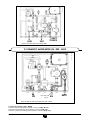
9.1 DOMESTIC WATER METER: R/1 - RP/1 - R2Z
0711_0602 / CR_0130
Figure 8 A: Domestic water meters (models R/1)
US 2
US 1
ESC 1
ESC 2
Figure 8 B: Domestic water meters (models RP/1)
1st meter (models R/1 – RP/1 – R2Z)
Domestic water metering inlet: hydraulic connector ESC1 (G 3/4”)
Domestic water metering outlet: hydraulic connector ES (G 1/2”) - US1
2nd meter (models R/1 – R2Z o RP/1)
Domestic water metering inlet: hydraulic connector ESC2 (G 3/4”)
Domestic water metering outlet: hydraulic connector US (G 1/2”) - US2
INSTALLATION AND OPERATING MANUAL
17
912.808.1 - IT
0707_2602 / CR_0120
ESC1
ESC2
US1
US2
Figure 8 C: Domestic water meters (models R2Z)
0707_2603 / CR_0032
9.2 DOMESTIC WATER METER: RS - RSP - RS2Z
US
cap to move or
remove
ES
ESC1
Figure 8 D: Domestic water meter (Models RS – RSP – RS2Z)
1st meter (models RS – RSP – RS2Z)
Domestic water metering inlet: hydraulic connector ESC1 (G 3/4”)
Domestic water metering outlet: hydraulic connector US (G 1/2”)
Domestic cold water metering outlet: hydraulic connector ES (G 1/2”)
INSTALLATION AND OPERATING MANUAL
18
912.808.1 - IT
INSTALLATION INSTRUCTIONS:
ELECTRICAL CONNECTIONS
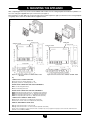
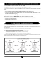
10. ELECTRICAL CONNECTIONS
The appliance is sold complete with electrical connections and power cable.
This machine is only electrically safe if it is correctly connected to an efficient earth system in compliance with current
safety regulations.
Connect the appliance to a 230V single-phase earthed power supply using the supplied three-pin cable, observing correct LIVE (L) - NEUTRAL (N) polarity.
Use a double-pole switch with a contact separation of at least 3mm.
When replacing the power supply cable, fit a harmonised HAR H05 VV-F’ 3x1 mm2 cable with a maximum diameter of 8
mm.
10.1 ACCESS TO THE POWER SUPPLY TERMINAL BLOCK
r %JTDPOOFDUUIFBQQMJBODFGSPNUIFNBJOTQPXFSTVQQMZVTJOHUIFUXPQPMFTXJUDI
r 3FNPWFUIFEPPSPGUIFDBTJOHVTJOHUIFTVQQMJFETRVBSFLFZ
r .BLFTVSFUIBUUIFTXJUDIJOEJDBUPSMJHIUJTPGG
r -PPTFOUIFTDSFXTPOUIFDPWFSPGUIFFMFDUSJDBMCPYBOESFNPWFJU
r 5IF"SBQJEGVTFJTJODPSQPSBUFEJOUIFQPXFSUFSNJOBMCMPDLNPEFMT3BOE31
PSJOUIFFMFDUSPOJDCPBSENPEFMT
RS, RSP, R2Z, RS2Z).
(L) = LIVE brown
(N) = NEUTRAL blue
= EARTH yellow-green
models R/1 - RP/1
Fuse
Electronic board
Fuse
0606_1006 / CR_0023
940225_0715
models RS – RSP – R2Z – RS2Z
Terminal
block
Fuse
Figure 9: Electric fuses
INSTALLATION AND OPERATING MANUAL
19
912.808.1 - IT
INSTALLATION AND OPERATING MANUAL
20
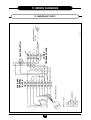
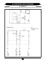
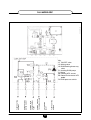
R = RED
V = GREEN
G = YELLOW
G/V = YELLOW/GREEN M
= BROWN
C = LIGHT BLUE
N = BLACK
WIRE COLOURS
INPUT SERVOMOTOR
PUMP (ONLY RP)
AUXILIARY
TERMINAL
BLOCK
POWER
TERMINAL BLOCK
FUSE
T.A.
ON/OFF BUTTON
0902_0808 / CR_0128
MAINS POWER INPUT
230V-50Hz
11. WIRING DIAGRAMS
11.1 MODELS R/1 E RP/1
912.808.1 - IT
INSTALLATION AND OPERATING MANUAL
21
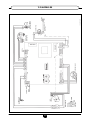
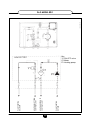
R = RED
V = GREEN
G = YELLOW
G/V = YELLOW/GREEN
M = BROWN
C = LIGHT BLUE
N = BLACK
WIRE COLOURS
INPUT
SERVOMOTOR
DOMESTIC HOT
WATER PROBE
SAFETY
THERMOSTAT
EXTERNAL PROBE
THREE-WAY VALVE
MIXING VALVE
SERVOMOTOR
0902_0809 / CR_008
MAINS POWER INPUT
230V-50Hz
ON/OFF BUTTON
DOMESTIC WATER
PRIORITY SENSOR
11.2 MODELS RS
912.808.1 - IT
INSTALLATION AND OPERATING MANUAL
22
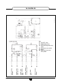
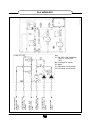
R = RED
V = GREEN
G = YELLOW
G/V = YELLOW/GREEN
M = BROWN
C = LIGHT BLUE
N = BLACK
WIRE COLOURS
INPUT
SERVOMOTOR
DOMESTIC HOT
WATER PROBE
SAFETY
THERMOSTAT
EXTERNAL PROBE
HEATING PROBE
THREE-WAY VALVE
MIXING VALVE
SERVOMOTOR
0902_0810 / CR_009
PUMP
MAINS POWER INPUT
230V-50Hz
ON/OFF BUTTON
DOMESTIC WATER
PRIORITY SENSOR
11.3 MODELS RSP
912.808.1 - IT
INSTALLATION AND OPERATING MANUAL
23
R = RED
V = GREEN
G = YELLOW
G/V = YELLOW/GREEN
M = BROWN
C = LIGHT BLUE
N = BLACK
WIRE COLOURS
INPUT
SERVOMOTOR
HIGH TEMP. ZONE
SERVOMOTOR
SAFETY
THERMOSTAT
EXTERNAL PROBE
HEATING PROBE
T.A. II ZONE T.A. I ZONE
0902_0811 / CR_007
PUMP P1 BT
PUMP P2 AT
MAINS POWER INPUT
230V-50Hz
ON/OFF BUTTON
MIXING VALVE
SERVOMOTOR
11.4 MODELS R2Z
912.808.1 - IT
INSTALLATION AND OPERATING MANUAL
24
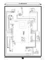
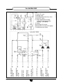
R = RED
V = GREEN
G = YELLOW
G/V = YELLOW/GREEN
M = BROWN
C = LIGHT BLUE
N = BLACK
WIRE COLOURS
INPUT
SERVOMOTOR
HIGH TEMP. ZONE
SERVOMOTOR
DOMESTIC HOT
WATER PROBE
HEATING PROBE
SAFETY
THERMOSTAT
EXTERNAL PROBE
THREE-WAY VALVE
T.A. II ZONE T.A. I ZONE
MIXING VALVE
SERVOMOTOR
0902_0812 / CR_0010
PUMP P1 BT
PUMP P2 AT
MAINS POWER INPUT
230V-50Hz
ON/OFF BUTTON
DOMESTIC WATER
PRIORITY SENSOR
11.5 MODELS RS2Z
912.808.1 - IT
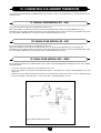
12. CONNECTING THE AMBIENT THERMOSTAT
The system must be fitted with an ambient thermostat in order to control room temperature. To connect this device, proceed as follows:
12.1 SINGLE-ZONE MODELS: R/1 – RP/1
Access the electrical components as described in section 10.1.
Remove the jumper on terminals (1) and (2) of the main terminal block (R/1, RP/1) (see wiring diagrams in § 11).
Thread the two-wire cable through the grommets of the electrical box and connect it to these two terminals using a harmo- nised cable “HAR H05 VV-F” 2 x 0.75 mm2 with a maximum diameter of 8 mm.
12.2 SINGLE-ZONE MODELS: RS – RSP
Access the electrical components as described in section 10.1.
Remove the jumper on the electronic board terminals (CN7: A - B) (see wiring diagrams in § 11 and Figure 10).
Thread the two-wire cable through the grommets of the electrical box and connect it to these two terminals using a harmo- nised cable “HAR H05 VV-F” 2 x 0.75 mm2 with a maximum diameter of 8 mm.
12.3 DUAL-ZONE MODELS: R2Z – RS2Z
These models are fitted for two ambient thermostats in order to provide independent management of two zones at different temperatures.
A.T. ZONE II
(MODELS R2Z-RS2Z-RA2Z)
0902_0813 / CR_0026
r "DDFTTUIFFMFDUSJDBMDPNQPOFOUTBTEFTDSJCFEJOTFDUJPO
r 3FNPWFUIFKVNQFSPOUIFFMFDUSPOJDCPBSEUFSNJOBMT$/"#
BOE$/%.
TFFXJSJOHEJBHSBNTJOfBOE
Figure 10).
r 5ISFBEUXPXJSFDBCMFTUISPVHIUIFHSPNNFUTPGUIFFMFDUSJDBMCPYBOEDPOOFDUUIFNUPUIFUXPUFSNJOBMTVTJOH
har- monised cables “HAR H05 VV-F” 2 x 0.75 mm2 with a maximum diameter of 8 mm.
A.T. ZONE II
BOARD CONNECTOR TO
WIRE
Figure 10: Ambient thermostat connections
INSTALLATION AND OPERATING MANUAL
25
912.808.1 - IT
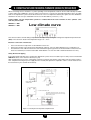
13. CONNECTING THE FLOOR OVERHEATING THERMOSTAT (MODELS RSP, R2Z AND RS2Z)
When connecting the user module to a system operating at low temperature, install an off-the-shelf manually resettable
contact thermostat (calibrated to 50°C) in order to protect the floor system from elevated temperatures due to possible
faults in the adjustment system. Mount the thermostat on the low temperature delivery line upline from the distribution
manifold to the various loops and distant from the user module delivery connector (> 1m).
Caution: Make sure low temperature operation is enabled. Electronic board switches 4 and 5 (climate curve
switches) must be OFF.
SWITCH 4 = OFF
SWITCH 5 = OFF
0902_0814 / CR_0028
Low climate curve
This selection allows central heating temperature to be adjusted by turning the heating water adjustment potentiometer
(TCH) on the electronic board. The temperature range is 25 ÷ 40 °C.
Electrical connection of thermostat
r
r
r
"DDFTTUIFFMFDUSJDBMDPNQPOFOUTBTEFTDSJCFEJOTFDUJPO
3FNPWFUIFKVNQFSPOUIFFMFDUSPOJDCPBSEUFSNJOBMT$/&%
TFFXJSJOHEJBHSBNTJOfBOE'JHVSF
5ISFBEUIFUXPXJSFDBCMFGSPNUIFUIFSNPTUBUUFSNJOBMTUISPVHIUIFHSPNNFUTPGUIFFMFDUSJDBMCPYBOEDPOOFDUJUUP
these two terminals (use a harmonised cable “HAR H05VV-F” 2x 0.75 mm2 with a maximum diameter of 8 mm).
Safety thermostat tripping
SIRIUS SAT BOARD
0902_0815 / CR_0025
If the safety thermostat trips due to a fault in the adjustment system, the user module stops for safety reasons and the red
LED DL12 shines on the electronic board (see § 22).
After checking the reason for the overheating, restart the system by pressing the safety thermostat reset device and momen- tarily disconnecting the power supply from the module (this operation is required in order to cancel the block from
the board memory: the red LED DL12 flashes).
RESETTABLE SAFETY
THERMOSTAT
Board connector
to wire
DUAL-ZONE SIRIUS SAT
Resettable safety thermostat to be exclusively
positioned on the delivery line of the low temperature heating system
Figure 11: Connecting the low temperature safety thermostat
INSTALLATION AND OPERATING MANUAL
26
912.808.1 - IT
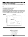
14. INSTALLING AND CONNECTING THE EXTERNAL PROBE
(accessory available on request for models RS, RSP, R2Z, RS2Z)
The appliance is fitted for connection to an external probe, available on request, which independently adjusts delivery
tem- perature depending on the external temperature and the chosen curve.
To mount and electrically connect this accessory, see the figure below and the instructions supplied with the external
probe.
The external probe must be installed on a wall outside the building as follows:
r *OTUBMMPOBXBMMGBDJOHOPSUIOPSUIFBTUBOEQSPUFDUFEGSPNEJSFDUTVOMJHIU
r %POPUJOTUBMMPOXBMMTBGGFDUFECZIVNJEJUZBOENPVME
r .BLFTVSFUIFXBMMJTTVGàDJFOUMZJOTVMBUFE
r %POPUJOTUBMMOFBSGBOTTUFBNPVUMFUTPSDIJNOFZT
Attach to the wall using the two supplied expansion grips, following the technical instructions supplied with the accessory Make electrical connections to the probe using two wires with a minimum cross-section of 0.5 mm2 and a maximum
length of 20 m (polarity is unimportant).
Fix one end of the Module-Probe connection cable to the probe terminal block, securing it with the relative sealed grommet, and the other end to the screw connector (CN4: B9 - M) on the electronic board (to access the electrical components
see section 10.1).Use a harmonised cable “HAR H05 VV-F” 2 x 0.75 mm2 with a maximum diameter of 8 mm.
Only models:
RSP-R2Z-RS2Z
0902_0816
Climate curves
Delivery temperature °C
High curve
Medium curve
Low curve
External temperature °C
Figure 12: External temperature – delivery temperature performance curve
With the external probe, the TCH potentiometer on the electronic board limits maximum heating temperature.
Attention: With the external probe connected, switch 6 on the electronic board must be turned ON.
External probe
0902_0817 / CR_0028
SELECTOR 6 = ON
INSTALLATION AND OPERATING MANUAL
27
912.808.1 - IT
15. CONNECTING THE CLIMATE ADJUSTOR: ECO CRONO
(accessory available on request: models RS – RSP – R2Z – RS2Z)
The LUNASAT module can be remote controlled using the ECO CRONO climate adjustor.
Connect the ECO CRONO climate adjustor to the ambient thermostat 1 terminals on the electronic board, as described
below:
r "DDFTTUIFFMFDUSJDBMDPNQPOFOUTBTEFTDSJCFEJOTFDUJPO
r 3FNPWFUIFKVNQFSPOUIFFMFDUSPOJDCPBSEUFSNJOBMT$/"#
TFFXJSJOHEJBHSBNTJOf
r $POOFDUBUXPXJSFDBCMFUPUIF&$0$30/0UFSNJOBMT+05
6TFBIBSNPOJTFEDBCMFi)"3)77'uY
mm2 with a maximum diameter of 8 mm.
r *OUSPEVDFUIFUXPXJSFDBCMFUISPVHIUIFHSPNNFUTPGUIFFMFDUSJDBMCPYBOEDPOOFDUJUUPUIFFMFDUSPOJDCPBSEUFSNJOBMT
(CN7: A-B). Also consult the manual supplied with the ECO CRONO.
With this device connected, the GREEN LED DL2 on the electronic board flashes at 5s intervals.
The instructions supplied with the ECO CRONO climate adjuster also include the information required to:
r QSPHSBNNFVTFSTFUUBCMFQBSBNFUFST
r QSPHSBNNFàUUFSTFUUBCMFQBSBNFUFST
r JOTUBMMUIFEFWJDF
16. ELECTRONIC BOARD ADJUSTMENT
(models RS – RSP – R2Z – RS2Z)
Caution: only make adjustments to the electronic board after disconnecting the power supply (see §10: access to
live components)
These adjustment can be made on electronically controlled models (apart from model RS):
TR = Heating temperature adjustment potentiometer (CH1)
Adjusts the heating delivery temperature according to the set climate curve.
TR temperature range TR: 25 ÷ 80°C (see climate curve selection table)
With the external probe, this device acts as a maximum temperature limiting device
0902_0818 / CR_0014
For dual-zone models (R2Z – RS2Z), heating temperature adjustment only applies to the mixed zone. The other zone works
directly with the temperature of the inlet water from the centralised system.
HEATING POTENTIOMETER
LOW
CLIMATE CURVE
MEDIUM
CLIMATE CURVE
HIGH
CLIMATE CURVE
Figure 13 A: Heating potentiometer (models: RSP-R2Z-RS2Z)
INSTALLATION AND OPERATING MANUAL
28
912.808.1 - IT
DOMESTIC HOT WATER
POTENTIOMETER
0902_0819 / CR_0014
TS = Domestic hot water (DHW) adjustment potentiometer
Adjusts domestic hot water temperature.
TS temperature range: 30 ÷ 60°C
Factory setting 45°C
Figure 13 B: Domestic hot water potentiometer
SELECTORS 1 – 2 – 3 : USER MODULE CONFIGURATIONS
Model selection table
MODEL
Switch 1
Switch 2
Switch 3
RS
OFF
OFF
OFF
RSP
ON
OFF
OFF
R2Z
OFF
ON
OFF
RS2Z
ON
ON
OFF
0903_2004 / CR_0015
Make sure the switches are in the correct position for the model
Figure 13 C: Model witches
INSTALLATION AND OPERATING MANUAL
29
912.808.1 - IT
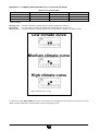
SWITCHES 4 – 5 : CLIMATE CURVE SELECTION (only for models RSP-R2Z-RS2Z))
Climate curve selection table
CLIMATE CURVE
Switch 4
Switch 5
Temperature range
LOW
OFF
OFF
25 ÷ 40 °C
MEDIUM
ON
OFF
50 ÷ 60 °C
HIGH (*)
OFF
ON
25 ÷ 80 °C
(*) factory setting
should be selected for heating elements at high temperatures: radiators
curve should be selected for heating elements fitted with fans: fan coil units
should be selected for heating elements at low temperatures: underfloor or similar systems.
Low climate curve
0902_0820 / CR_0028
The high curve
The medium
The low curve
Medium climate curve
High climate curve
Figure 13 D: Climate curve selectors
For dual-zone models (R2Z – RS2Z), the choice of the climate curve only applies to the mixed zone. The other zone works
directly with the temperature of the inlet water from the centralised system.
INSTALLATION AND OPERATING MANUAL
30
912.808.1 - IT
SWITCH 6: EXTERNAL PROBE ENABLE (only for models RSP-R2Z-RS2Z))
External probe enable table
EXTERNAL PROBE
Switch 6
WITH PROBE
ON
WITHOUT PROBE (*)
OFF
(*) factory setting
0902_0902 / CR_0028
External probe
Figure 13 E: External Probe Switch
SELECTOR 7 : PUMP POST-CIRCULATION TIME
Pump post-circulation time selection table
EXTERNAL PROBE
Switch 7
WITH PROBE
ON
WITHOUT PROBE (*)
OFF
(*) factory setting
0902_0903 / CR_0028
Pump post-circulation
Figure 13 F: Pump post-circulation switch
INSTALLATION AND OPERATING MANUAL
31
912.808.1 - IT
INSTALLATION INSTRUCTIONS:
HEAT METERING
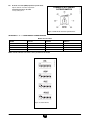
17. HEAT METERING
The modules are supplied standard with a SIEMENS MEGATRON electronic heat meter.
This device measures heat consumption in the zone controlled by the user module.
The electronic unit features an 8-digit LCD display. The 3 Vdc input voltage is provided by a lithium battery (lifetime 8
years). A button for querying the appliance is located on the front of the display.
The appliance can be turned by 360° and inclined by 90°.
The appliance display has two levels with which the following information can be shown:
r 5PUBMQPXFSDPOTVNFETJODFUIFMBTUSFBEJOHEBUF
r 4FHNFOUUFTU
r $VSSFOUDPOTVNQUJPO
r $VSSFOUáPXSBUF
r $VSSFOUEFMJWFSZUFNQFSBUVSF
r $VSSFOUSFUVSOUFNQFSBUVSF
r $VSSFOU5%FMUBCFUXFFOUIFUXPUFNQFSBUVSFT
r 0QFSBUJOHIPVSTTJODFJOJUJBMTUBSUVQ
r -BTUSFBEJOHEBUF
r -BTUZFBSATQPXFSDPOTVNQUJPO
r $IFDLDPEF
r 5PUBMQPXFSDPOTVNQUJPOTJODFJOTUBMMBUJPO
r 'BVMUTJHOBMTDPOTVMUUIFGPMMPXJOHTFDUJPO
The units of measurement are °C or K, kWh, m3/h, kW, and hours.
The display shows total heating consumption by default.
Fault signals
The appliance automatically carries out diagnostic controls and displays the faults it finds. It divides the faults into two
cat- egories.
Temporary faults that do not cause operating problems. In this case, the display flashes for 32 seconds and then resumes
normal operation;
Major faults that stop the appliance. In this case, the display alternatively indicates the fault code and the date on n which
it appeared for the first time. The flows metered up until that moment, remain memorised.
0606_1021
For further information, see the supplied SIEMENS instructions supplied with the meter.
Figure 14: Meter display
Metering data can also be transmitted via radio to a remote reception device (Radio system expansion).
INSTALLATION AND OPERATING MANUAL
32
912.808.1 - IT
18. AUTOMATIC MEASUREMENT SYSTEM VIA RADIO
This system allows all the consumption data of the building to be handled from a single station, thus reducing measurement times whilst protecting user privacy. Transmission frequency is the 868 MHz established by the national radio transmission plan (European standard). The duration and power of the radio signal are irrelevant and are in no way connected
with prob- lems of “electro smog”.
The heat meters of the various user modules transmit consumption via a radio signal and the relative floor aerials (WTT16)
which receive and save the data. Consumption can be read by connecting a Personal computer to any of the floor aerials
via radio or making a cable connection to an aerial with a serial output or using a remote modem (GSM).
r
r
r
-PDBMSFBEJOHWJBDBCMFGSPNUIF855232 aerial with RS232 interface:
via PC (with ACS26 data reading software) connected with a serial cable (figure 15b case 1).
-PDBMSFBEJOHWJBSBEJPPGUIFWTT16 floor aerials:
via PC (with ACS26 data reading software) connected to the WTZ.RM radio module (figure 15b case 2).
3FNPUFSFBEJOHWJB(4.GSPNUIFWTX16.GSM Gateway aerial:
Via PC (with ACS26 reading software and GSM modem + phone card) (figure 15b case 3).
In certain cases, the following accessory components must be used:
t
t
t
t
t
855'-003"&3*"855"&3*"-8*5)4&3*"-065165MPDBMSFBEJOHWJB1$
859(4.("5&8":"&3*"-UFMFQIPOFSFBEJOHWJB1$
4*&.&$"85;3.3"%*0.0%6-&'031$SBEJPSFBEJOHWJB1$
"$43&"%*/(40'58"3&GPS1$
During installation, no special start-up procedures are required for radio transmissions as all the system components
are
automatically configured for signal transmissions. These characteristics guarantee rapid, problem-free start-up and simple system management.
Install the Radio system according to the following parameters:
r
r
r
r
r
"WFSBHFSFDFQUJPODBQBDJUZPG855BFSJBMTSBEJVTPGNFUSFTPOUIFáPPSXIFSFUIFZBSFJOTUBMMFEBOENFUSFT
on the floors above and below (install one WTT16 aerial every two floors).
4ZTUFNDBQBDJUZNBY855BFSJBMTPS855BFSJBMT("5&8":859BFSJBM
XJUINBYSFDFQUJPOPG
500 meters.
-JGFUJNFPGCBUUFSZPQFSBUFE855BFSJBMBUMFBTUZFBSTQMVTSFTFSWFZFBSEVSJOHXIJDIBiCBUUFSZMPXuNFTTBHF
is sent
-JGFUJNFPGIFBUNFUFSZFBSTQMVTSFTFSWFNPOUIT
5IF859(4.(BUFXBZBFSJBMNVTUCFQPXFSFEBUNBJOTWPMUBHF
The floor aerials (WTT16) must be fixed to a wall of the stairwell, at a height that prevents tampering, using the supplied
expansion grip. The Gateway aerial (WTX16.GSM) must be installed in the entrance area of the metered building (this
com- ponent requires mains voltage input).
INSTALLATION AND OPERATING MANUAL
33
912.808.1 - IT
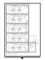
HOME A
0902_0905 / CR_0027
FLOOR AERIAL
RADIO TRANSMISSION 868 MHz
HOME B
RADIO TRANSMISSION 868 MHz
HOME A
HOME B
RADIO TRANSMISSION 868 MHz
FLOOR
AERIAL
HOME A
HOME B
RADIO TRANSMISSION 868 MHz
PHONE TRANSMISSION GSM
HOME A
HOME B
RADIO TRANSMISSION 868 MHz
(SEE OPTIONS IN
FIGURE 15B)
HOME A
HOME B
Figure 15 A: Automatic measurement system via radio
INSTALLATION AND OPERATING MANUAL
34
912.808.1 - IT
2) LOCAL TRANSMISSION
VIA “RADIO”
0902_0904 / CR_0033
1) LOCAL TRANSMISSION
VIA “SERIAL”
AERIAL
AERIAL
3) TRANSMISSION VIA “GSM”
REMOTE OFFICE
AERIAL
GSM
MODEM
METERED BUILDING
Figure 15 B: Reading options
INSTALLATION AND OPERATING MANUAL
35
912.808.1 - IT
18.1 START-UP
Start-up of the radio system comprises several steps:
r 4FUUIF855BFSJBMTUPUIFTUBSUVQNPEFQSFTTUIFSFE.0%&CVUUPOPOFBDI855BFSJBM
r "UUIJTQPJOUUIF855BFSJBMTDPOàHVSFUIFNTFMWFTBOEBVUPNBUJDBMMZDSFBUFBWJSUVBMDPNNVOJDBUJPOOFUXPSL
r 4FUUIFIFBUNFUFSUPUIFTUBSUVQNPEFCZQSFTTJOHUIFCVUUPOPOUIFGSPOU"GUFSTFUUJOHUIFNPEFBMMUIFNFUFSTTFOE
a start-up signal to the WTT16 aerials.
r "GUFSSFDFJWJOHBMMUIFNFUFSTJOUIFàFMEUPDPNQFUFTZTUFNTUBSUVQTFUUIFBFSJBMTUPUIFTUBOEBSENPEFQSFTTUIF
blue button on each WTT16 aerial).
18.2 OPERATING PROCEDURE
During automatic system operation, the WTT16 aerials and the GATEWAY WTX16.GSM aerial exchange the consumption
data of the meters on a daily basis in order to allow each single aerial to store the data of the entire building. The data of
the entire building can be manually updated without having to wait for the daily exchange routine.
18.3 DATA FORMAT
Consumption data is coded in XML format or in ASCII code to that it can be processed by any editor (Notepad, Excel,
etc.).
For further information, read the manuals of the individual components.
INSTALLATION AND OPERATING MANUAL
36
912.808.1 - IT
START-UP AND OPERATING INSTRUCTIONS
19. FILLING THE SYSTEM
Before starting the user module, open the on/off valves on the hydraulic connectors and check the system filling pressure
in the boiler room and distribution columns (< 3 bar).
The centralised plant must have an automatic filling device.
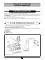
20. AIR VENT AND PUMP RESET
20.1 AIR VENT
In the first plant filling operation, vent any air in the system, including the user module. The appliance is fitted with an
automatic air vent valve.
20.2 PUMP RESET (MODELS: RP/1 – RSP - R2Z – RS2Z)
The user module is fitted with a pump reset device (not present in model RP/1) which, if no heat demand (heating and/
or domestic water) is received for 24 consecutive hours, automatically runs the pump for one minute. This function is
operative if the system is powered.
If, however, the pump/s need/s to be reset after a period of inactivity or during initial starting, simply remove the cap
screwed onto the shaft, insert a screwdriver and turn the rotor a few times in order to reset it and allow it to start. Collect
the water flowing from the pump shaft.
INSTALLATION AND OPERATING MANUAL
37
912.808.1 - IT
21. OPERATING PROCEDURE
21.1 STARTING
To start the appliance correctly, proceed as follows:
r
r
r
r
r
1PXFSUIFNPEVMF
$IFDLUIBUUIFTZTUFNJTGVMMBOEBUUIFSJHIUQSFTTVSFTFFf
BOEUFNQFSBUVSF$
'PSNPEFMTXJUIFMFDUSPOJDCPBSEDIFDLUIBUUIFFMFDUSPOJDCPBSETXJUDIFTBSFJOUIFDPSSFDUQPTJUJPOTFFf
1SFTTUIFMVNJOPVTTXJUDIPOUIFDPWFSPGUIFFMFDUSJDBMCPY
"EKVTUUIFBNCJFOUUIFSNPTUBUPSUIFDMJNBUFBEKVTUPS
UPUIFSFRVJSFEUFNQFSBUVSF
Following a heat demand from the ambient thermostat, the water from the centralised system begins to circulate in the
heating elements of the zone controlled by the user module.
For dual-zone models (R2Z – RS2Z) the heating bands of two zones can be managed separately by the relative ambient thermostats (or with the ECO CRONO climate adjustor).
For models RS – RSP – RS2Z (with plate exchanger), when a domestic hot water tap is opened, the user module heats
the water at the temperature set by the relative DHW potentiometer. TS temperature range: 30 ÷ 60°C (see § 16).
Different adjustments of domestic hot water temperature can be made directly using the ECO CRONO climate adjuster.
21.2 PARTIAL SHUT-DOWN
Adjust the ambient thermostat / heating programmer / ECO CRONO climate adjuster to disable the heating function (lower the set ambient temperature or disable heating). The domestic hot water function (models RS – RSP – RS2Z) and the
frost protection device (only for RS – RSP – RS2Z) remain active).
21.2 TOTAL SHUT-DOWN
Disconnect the appliance from the power supply by turning the luminous switch and the two-pole switch.
INSTALLATION AND OPERATING MANUAL
38
912.808.1 - IT
22. ELECTRONIC BOARD SIGNALS (MODELS RS – RSP – R2Z – RS2Z)
5IFNPEFMTXJUIFMFDUSPOJDCPBSEEJTQMBZUIFPQFSBUJOHTUBUVTBOEBOZTZTUFNCMPDLTWJBUIFCPBSE-&%AT
Key to LED‘s:
LED
COLOUR LED STATUS
OPERATING STATUS
DL1
RED
OFF
NO ALARMS
DL1
RED
1 FLASH EVERY 3 SECONDS
EXTERNAL PROBE FAULTY
DL1
RED
2 FLASHES EVERY 1 SECOND
DOMESTIC HOT WATER PROBE FAULTY
DL1
RED
3 FLASHES EVERY 1 SECOND
HEATING PROBE FAULTY
DL1
RED
ON
ON/OFF VALVE CLOSED
DL2
GREEN
OFF
NO POWER
DL2
GREEN
ON
ZONE I HEAT DEMAND (MIXED)
DL2
GREEN
1 FLASH EVERY 0.5 SECONDS
POWER ON (NON-OPENTHERM AMBIENT THERMOSTAT)
DL2
GREEN
1 FLASH EVERY 0.5 SECONDS
POWER ON (OPENTHERM: QAA73 AMBIENT THERMOSTAT)
DL3
GREEN
ON
ZONE II PUMP FEED (HIGH TEMPERATURE)
DL4
GREEN
ON
ZONE 1 PUMP FEED (MIXED)
DL5
GREEN
ON
ON/OFF VALVE SERVOMOTOR POWER INPUT
DL6
GREEN
ON
DOMESTIC HOT WATER CIRCULATION PUMP (NON-OPERATIVE)
DL7
GREEN
ON
ZONE II VALVE OPEN
DL8
GREEN
ON
DOMESTIC HOT WATER THREE-WAY VALVE
DL9
GREEN
ON
HEATING THREE-WAY VALVE
DL10
GREEN
ON
DOMESTIC HOT WATER DEMAND
DL11
GREEN
ON
ON/OFF VALVE OPEN (AT TRAVEL STOP)
DL12
RED
ON
SAFETY THERMOSTAT TRIPPED (*)
DL12
RED
FLASHING
AFTER SAFETY THERMOSTAT RESET (*)
DL13
GREEN
ON
ZONE II HEAT DEMAND
(*) Safety thermostat tripping
If the safety thermostat trips due to a fault in the adjustment system, the user module stops for safety reasons and the red
LED DL12 shines on the electronic board.
After checking the reason for the overheating, restart the system by pressing the safety thermostat reset device and
momen- tarily disconnecting the power supply from the module (this operation is required in order to cancel the block
from the board memory: the red LED DL12 flashes). In case this device trips repeatedly, contact the technical assistance
service.
INSTALLATION AND OPERATING MANUAL
39
912.808.1 - IT
0902_0906 / CR_0024
Safety thermostat tripping
Red indicator LED
Green indicator LED
Red indicator LED
Red indicator LED
Green indicator LED
Green indicator LED
Figure 16: Electronic board signals
INSTALLATION AND OPERATING MANUAL
40
912.808.1 - IT
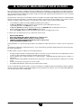
MAINTENANCE INSTRUCTIONS
For regular and cost-effective operation of the user modules, they must be periodically checked and overhauled approxima- tely once every two years.
23. DISMOUNTING/ CLEANING THE DOMESTIC HOT WATER EXCHANGER
(only for models RS – RSP – RS2Z)
The stainless steel domestic hot water plate-type heat exchanger can be easily disassembled with a screwdriver as described below:
r
r
r
r
r
$MPTFBMMUIFPOPGGUBQTPOUIFIZESBVMJDDPOOFDUPSTPGUIFNPEVMF
&NQUZUIFIFBUJOHDJSDVJUXJUIUIFSFMBUJWFESBJOUBQ
&NQUZUIFXBUFSJOUIFEPNFTUJDIPUXBUFSDJSDVJUCZPQFOJOHBIPUXBUFSUBQ
3FNPWFUIFCZQBTTQJQFCZSFMFBTJOHUIFàYJOHTQSJOHT
3FNPWFUIFUXPGSPOUTDSFXTTFDVSJOHUIFXBUFSXBUFSIFBUFYDIBOHFSBOEQVMMJUPVU
0606_1025 / CR_0019
To clean the exchanger and/or DHW circuit, use Cillit FFW-AL or Benckiser HF-AL. Remove the scale from the seat and
relative NTC sensor fitted on the DHW circuit.
REMOVE
BYPASS
DRAIN TAP
REMOVE THE SCREWS
DHW
EXCHANGER
REMOVE THE SCREWS
Figure 17: Dismounting the DHW exchanger
INSTALLATION AND OPERATING MANUAL
41
912.808.1 - IT
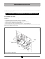
24. CLEANING THE HEATING INLET FILTER
These appliances are fitted with a heating water filter on the water inlet line coming from the centralised plant. To clean,
proceed as follows:
0607_0303 / CR_0020
r $MPTFBMMUIFPOPGGUBQTPOUIFIZESBVMJDDPOOFDUPSTPGUIFNPEVMF
r &NQUZUIFIFBUJOHDJSDVJUusing the relative drain tap for models RS – RSP – R2Z – RS2Z);
r 6OTDSFXUIFDBQBUUIFUPQPGUIFàMUFSSFNPWFUIFJOUFSOBMDZMJOEFSDBSUSJEHFBOEFMJNJOBUFBOZJNQVSJUJFT
filter cap
filter
cartridge
Figure 18: Dismounting the heating circuit filter
INSTALLATION AND OPERATING MANUAL
42
912.808.1 - IT
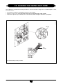
25. CLEANING THE COLD WATER FILTER (only for models RS – RSP – RS2Z )
The module is fitted with a cold water filter on the hydraulic assembly.
To clean, proceed as follows:
r
r
r
r
%SBJOUIFEPNFTUJDIPUXBUFSTZTUFN
6OTDSFXUIFOVUPOUIFáPXTFOTPSBTTFNCMZàHVSF
1VMMPVUUIFáPXTFOTPSBOEJUTàMUFS
3FNPWFBOZJNQVSJUJFT
0607_0304 / CR_0021
IMPORTANT: when replacing and/or cleaning the O-rings on the hydraulic assembly, only use Molykote 111 as a lubricant, not oil or grease.
filter
Figure 19: Cleaning the domestic hot water filter
INSTALLATION AND OPERATING MANUAL
43
912.808.1 - IT
PLANT HEATING
RETURN
HEATING RETURN TO
CENTRAL PLANT
HEATING INLET FROM
CENTRAL PLANT
PLANT HEATING
DELIVERY
0902_0907 / CR_0138
26. FUNCTIONAL CIRCUIT DIAGRAM
26.1 MODEL R/1
Key
Y1 ON-OFF valve
C1 Meter
INSTALLATION AND OPERATING MANUAL
44
912.808.1 - IT
PLANT HEATING
RETURN
HEATING RETURN TO
CENTRAL PLANT
HEATING INLET FROM
CENTRAL PLANT
PLANT HEATING
DELIVERY
0902_1102 / CR_0139
26.2 MODEL RP/1
Key
Y1 ON-OFF valve
C1 Meter
P1 Heating pump
INSTALLATION AND OPERATING MANUAL
45
912.808.1 - IT
0902_0909 / CR_0004
26.3 MODEL RS
INSTALLATION AND OPERATING MANUAL
46
PLANT HEATING
RETURN
COLD WATER
INLET
HEATING RETURN
TO CENTRAL PLANT
HEATING INLET
FROM CENTRAL
PLANT
DOMESTIC HOT
WATER OUTLET
PLANT HEATING
DELIVERY
Key
Y1 ON-OFF valve
Y2 Modulating valve
Y3 DHW/heating three-way
valve
Y4 DHW pressure switch
C1 Meter
B5 Domestic hot water
NTC probe
912.808.1 - IT
0902_0910 / CR_0005
26.4 MODEL RSP
INSTALLATION AND OPERATING MANUAL
47
PLANT HEATING
RETURN
COLD WATER
INLET
HEATING RETURN
TO CENTRAL PLANT
HEATING INLET
FROM CENTRAL
PLANT
DOMESTIC HOT
WATER OUTLET
PLANT HEATING
DELIVERY
Key
Y1 ON-OFF valve
Y2 Mixing valve
Y3 DHW/heating three-way
valve
P1 Heating-DHW pump
C1 Meter
B4 Heating NTC sensor
B5 Domestic hot water NTC
probe
F4 DHW pressure switch
912.808.1 - IT
INSTALLATION AND OPERATING MANUAL
48
PLANT HEATING
RETURN
LOW TEMPERATURE
PLANT HEATING
RETURN
HEATING RETURN
TO CENTRAL PLANT
HEATING INLET
FROM CENTRAL
PLANT
LOW TEMPERATURE
PLANT HEATING
DELIVERY
HIGH TEMPERATURE
PLANT HEATING
DELIVERY
0902_0911 / CR_0003
26.5 MODEL R2Z
Key
Y1 ON-OFF valve Y2 Mixing
valve l.v. Y3 ON-OFF
valve
B4 Heating NTC sensor
C1 Meter
P1 High temp. circuit pump
P2 Low temp. circuit pump
912.808.1 - IT
INSTALLATION AND OPERATING MANUAL
49
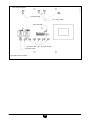
HIGH TEMPERATURE
PLANT HEATING
RETURN
LOW TEMPERATURE
PLANT HEATING
RETURN
COLD WATER INLET
HEATING RETURN
TO CENTRAL PLANT
HEATING INLET
FROM CENTRAL
PLANT
DOMESTIC HOT
WATER OUTLET
LOW TEMPERATURE
PLANT HEATING
DELIVERY
HIGH TEMPERATURE
PLANT HEATING
DELIVERY
Key
Y1 ON-OFF valve
Y2 Mixing valve
Y3 DHW/heating three-way valve
Y4 ON-OFF valve
P1 High temperature heating
pump P2 Low temperature
heating - DHW pump
C1 Meter
B4 Heating NTC sensor
B5 Domestic hot water NTC probe
F4 DHW pressure switch
0902_0912 / CR_0006
26.6 MODEL RS2Z
912.808.1 - IT
27. DISPOSAL
This product has been built with materials that do not pollute the environment. At the end of its lifetime, do not treat it as
domestic waste but take it to the nearest appliance recycling plant.
Disposal must be performed according to current environmental waste disposal laws.
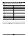
28. TECHNICAL DATA
SIRIUS SAT user modules
R/1
RP/1
RS
RSP
R2Z
RS2Z
Production of domestic hot water
-
-
●
●
-
●
Models with pump
-
●
-
●
●
●
Dual-zone models
-
-
-
-
●
●
Heating water temperature adjustment with climate curve high
°C
-
-
25÷80 25÷80 25÷80 25÷80
Adjustment of domestic hot water temperature
°C
-
-
30÷60 30÷60
l/min
-
-
14,3
Maximum pressure in heating circuit
bar
4
4
4
Maximum pressure in domestic hot water circuit
bar
-
-
Minimum dynamic pressure in domestic hot
water circuit
bar
-
-
Production of domestic hot water with ∆T = 35°C
and Inlet water temperature 75°C
-
30÷60
14,3
-
14,3
4
4
4
8
8
-
8
0,2
0,2
-
0,2
Water content
l
1,5
2
2
2,5
3,5
4
Input voltage
V
230
230
230
230
230
230
Input frequency
Hz
50
50
50
50
50
50
Rated electrical input
W
15
110
15
110
210
210
Width of casing
mm
600
600
600
600
800
800
Height of casing
mm
650
650
650
650
750
750
Depth of casing
mm
150
150
150
150
150
150
kg
11
13
16
18
22
25
Net weight
INSTALLATION AND OPERATING MANUAL
50
912.808.1 - IT
INSTALLATION AND OPERATING MANUAL
51
912.808.1 - IT
Baxi Commercial Division
Wood Lane, Erdington,
Birmingham B24 9QP
Email: [email protected]
www.andrewswaterheaters.co.uk
Sales:
0845 070 1056
Technical:
0845 070 1057
heating specialists