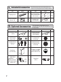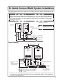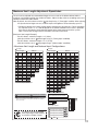
1
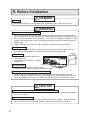
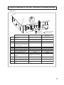
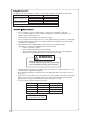
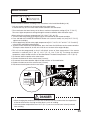
EN CONDENSING TANKLESS GAS WATER HEATER SP CALENTADOR A GAS TIPO CONDENSADO SBB800T Rev. 11/12 Installation Manual Manual de Instalación 5995615357 November 2012 *SBB800T* Installation Manual CONDENSING TANKLESS GAS WATER HEATER EN19WI30LS EP19WI30LS Potential dangers from accidents during installation and use are divided into the following three categories. Closely observe these warnings, they are critical to your safety. DANGER WARNING CAUTION DANGER indicates an imminently hazardous situation which, if not avoided, will result in death or serious injury. WARNING indicates a potentially hazardous situation which, if not avoided, could result in death or serious injury. CAUTION indicates a potentially hazardous situation which, if not avoided, may result in minor or moderate injury. WARNING: If the information in this manual is not followed exactly, a fire or explosion may result causing property damage, personal injury or death. Prohibited Disconnect Power Ground Be sure to do CAUTION Requests to Installers r*OPSEFSUPVTFUIFXBUFSIFBUFSTBGFMZSFBEUIJTJOTUBMMBUJPONBOVBMDBSFGVMMZBOEGPMMPXUIF installation instructions. r'BJMVSFTBOEEBNBHFDBVTFECZFSSPOFPVTXPSLPSXPSLOPUBTJOTUSVDUFEJOUIJTNBOVBMBSFOPU covered by the warranty. r$IFDLUIBUUIFJOTUBMMBUJPOXBTEPOFQSPQFSMZJOBDDPSEBODFXJUIUIJT*OTUBMMBUJPO.BOVBMVQPODPNQMFUJPO r"GUFSDPNQMFUJOHJOTUBMMBUJPOQMFBTFFJUIFSQMBDFUIJT*OTUBMMBUJPO.BOVBMJOBQMBTUJDQPVDIBOE attach it to the side of the water heater (or the inside of the pipe cover or recess box if applicable), or hand it to the customer to retain for future reference. Also, be sure to fill in all of the required items on the registration/warranty card and to hand the registration/warranty card to the customer BMPOHXJUIUIF6TFBOE$BSF.BOVBM Low NOx Approved by 4$"2.% OH+PSQQN (Natural Gas Only) '0364&*/3&4*%&/5*"-"11-*$"5*0/4*/5)&6/*5&%45"5&40/-: /05*/5&/%&%'0364&*/$"/"%"03.&9*$0 Installation must conform with local codes, or in the absence of local codes, UIF/BUJPOBM'VFM(BT$PEF"/4*;/'1"MBUFTUFEJUJPOBOEPS $4"#/BUVSBM(BTBOE1SPQBOF*OTUBMMBUJPO$PEF/4$/(1*$ &MFDUSPMVY )PNF 1SPEVDUT *OD SFTFSWFT UIF SJHIU UP EJTDPOUJOVF PS change at any time, the designs and/or specifications of its products without notice. 1. Included Accessories The following accessories are included with the unit. $IFDLGPSBOZNJTTJOHJUFNTCFGPSFTUBSUJOHJOTUBMMBUJPO Q’ty Part Tapping Screw 6TFBOE$BSF.BOVBM 8BSSBOUZ*OTUBMMBUJPO.BOVBM (this document) 1 each Remote Controller 4FFQ 1 Remote Controller $PSEGUN 3$$03% 1 Part Shape 2. Optional Accessories Part Q’ty Q’ty The accessories listed below are not included with the units, but may be necessary for installation. Part Shape Q’ty 2VJDL$POOFDU$PSE (2$) 1 Remote Controller $PSEGUN 3$$03% 1 NN PVC Terminal 7,)17$ 1 Bird Screen for NN 17$ 7517$4 1 each Bird Screen for NN 17$ 7517$4 Pipe Cover (1$4464) 1 NN NN )PSJ[POUBM)PPE 5FSNJOBUJPO175)- SV Conversion Kit (47$,) r&MCPX (With Inlet Screen) r*OTUBMMBUJPO.BOVBM $IFDL-JTU 1 each Neutralizer /$ 1 Isolation Valves (includes pressure relief valve) Shape Shape 3. Quick Connect Multi System Installation r5IF2VJDL$POOFDU.VMUJ4ZTUFNBMMPXTUIFJOTUBMMBUJPOPGUXPVOJUTUPHFUIFSVUJMJ[JOHPOMZUIF2VJDL Connect Cord. 5IF2VJDL$POOFDU$PSEJTGUN MPOH*OTUBMMUIFVOJUTNN BQBSUGSPNFBDI other to ensure the cord will be able to reach between the units. (See Typical Plumbing diagram). (If the distance between the two units is too great, not only will the cord not be able to reach, but the water temperature may also become unstable because of the difference in pipe length between the two units). System Diagram Quick Connect Cord * When connecting two units, use only a single remote controller. Cord Connector Cord Connector Terminal Block Remote Controller Note: Connect the remote controller to only one of the units. Remote Controller Cord Gas Supply Piping G Cold Water Supply Hot Water Typical Plumbing Distance at center: 20.3 - 36.3 in. (515 - 922mm) Distance on sides 2 - 18 in. (50 - 457mm) Union Quick Connect Cord Make this distance as short as possible. * The hot water temperature will become unstable as the pipe length increases. Union Union Pressure Relief Valve Size the piping to allow for the maximum flow rates of the units. Shutoff Valve Gas Valve Shutoff Valve Hot Water Cold Water Shutoff Valve Leave enough clearance around the plumbing to apply insulation. It will be necessary to add bends to the piping to ensure that this clearance is available. The backflow preventer is put up before it diverges. r*OTVMBUF UIF IPU XBUFS QJQJOH UP QSFWFOU IFBU MPTT *OTVMBUF BOE BQQMZ IFBUJOH NBUFSJBMT UP the cold water supply piping to prevent heat loss and freezing of pipes when exposed to excessively cold temperatures. 3 4. Before Installation DANGER Checkup r$IFDLUIFàYJOHCSBDLFUTBOEWFOUQJQFZFBSMZGPSEBNBHFPSXFBS3FQMBDFJGOFDFTTBSZ WARNING Precautions on Vent Pipe Replacement r5IFWFOUTZTUFNXJMMBMNPTUDFSUBJOMZOFFEUPCFSFQMBDFEXIFOUIJTBQQMJBODFJTCFJOHJOTUBMMFE 0OMZVTFWFOUNBUFSJBMTUIBUBSFTQFDJàFEJOUIJT*OTUBMMBUJPO.BOVBMGPSVTFPOUIJTBQQMJBODF3FGFS UPUIF7FOU1JQF*OTUBMMBUJPOTFDUJPOGPSEFUBJMT*G17$$17$PS$BUFHPSZ*7MJTUFEQJQFJTBMSFBEZ JOTUBMMFEDIFDLGPSQVODUVSFTDSBDLTPSCMPDLBHFTBOEDPOTVMUXJUIUIFWFOUQJQFNBOVGBDUVSFS before reusing. *NQSPQFSWFOUJOHNBZSFTVMUJOàSFTQSPQFSUZEBNBHFPSFYQPTVSFUP$BSCPO.POPYJEF Snow Precaution r*GUIJTQSPEVDUXJMMCFJOTUBMMFEJOBOBSFBXIFSFTOPXJTLOPXOUPBDDVNVMBUFQSPUFDUUIFWFOU UFSNJOBUJPOGSPNCMPDLBHFCZTOPXESJGUTPSEBNBHFGSPNTOPXGBMMJOHPGGPGSPPGT Check the Gas r$IFDLUIBUUIFSBUJOHQMBUFJOEJDBUFTUIF correct type of gas. r$IFDLUIBUUIFHBTTVQQMZMJOFJTTJ[FEGPS 199,900 Btuh. EN19WI30LS1 199,900 BTU 228 16,000 BTU 4.0 1.3 15 10.5" 2.8" 150 4 Check the Power r5IFQPXFSTVQQMZSFRVJSFEJT7"$BU)[ 6TJOHUIFJODPSSFDUWPMUBHFNBZSFTVMUJOàSFPSFMFDUSJDTIPDL ANSI Z21.10.3-2011/CSA 4.3-2011 Use Extreme Caution if Using With a Solar Pre-Heater r6TJOHUIJTVOJUXJUIBTPMBSQSFIFBUFSDBOMFBEUPVOQSFEJDUBCMFPVUQVUUFNQFSBUVSFTBOE possibly scalding. If absolutely necessary, use mixing valves to ensure output temperatures do OPUHFUUPTDBMEJOHMFWFMT%POPUVTFBTPMBSQSFIFBUFSXJUIUIFRVJDLDPOOFDUNVMUJTZTUFN CAUTION Do Not Use Equipment for Purposes Other Than Those Specified r%POPUVTFGPSPUIFSUIBOJODSFBTJOHUIFUFNQFSBUVSFPGUIFXBUFSTVQQMZBTVOFYQFDUFEBDDJEFOUT may occur as a result. Check Water Supply Quality r*GUIFXBUFSTVQQMZJTJOFYDFTTPGHSBJOTQFSHBMMPONH- PGIBSEOFTTBDJEJDPSPUIFSXJTF impure, treat the water with approved methods in order to ensure full warranty coverage. 5. Choosing Installation Site -PDBUFUIFBQQMJBODFJOBOBSFBXIFSFMFBLBHFGSPNUIFVOJUPSDPOOFDUJPOTXJMMOPUSFTVMUJOEBNBHF to the area adjacent to the appliance or to the lower floors of the structure. When such locations cannot be avoided, it is recommended that a suitable drain pan, adequately drained, be installed under the appliance. The pan must not restrict combustion air flow. DANGER rLocate the vent terminal so that there are no obstacles around the termination and so that exhaust can't accumulate. Do not enclose the termination with corrugated metal or other materials. WARNING r"WPJEQMBDFTXIFSFàSFTBSFDPNNPOTVDIBTUIPTFXIFSFHBTPMJOF benzene and adhesives are handled, or places in which corrosive gases (ammonia, chlorine, sulfur, ethylene compounds, acids) are present. 6TJOHUIFJODPSSFDUWPMUBHFNBZSFTVMUJOàSFPSDSBDLJOH Prohibited r"WPJEJOTUBMMBUJPOJOQMBDFTXIFSFEVTUPSEFCSJTXJMMBDDVNVMBUF %VTUNBZCMPDLUIFBJSTVQQMZPQFOJOHDBVTJOHUIFQFSGPSNBODFPGUIF device fan to drop and incomplete combustion to occur as a result. r"WPJEJOTUBMMBUJPOJOQMBDFTXIFSFTQFDJBMDIFNJDBMBHFOUT (e.g., hair spray or spray detergent) are used. Ignition failures and malfunction may occur as a result. r$BSCPO.POPYJEF1PJTPOJOH)B[BSE%POPUJOTUBMMUIJTXBUFSIFBUFSJOB recreational vehicle or on a boat. CAUTION r5IFXBUFSIFBUFSJTEFTJHOFEGPSJOEPPSJOTUBMMBUJPOPOMZ/FWFSJOTUBMMJU outdoors or in a bathroom, it may be damaged or a fire may be caused. r$POTVMUXJUIUIFDVTUPNFSDPODFSOJOHUIFMPDBUJPOPGJOTUBMMBUJPO rInstall the water heater in an area that allows for the proper clearances to combustible and noncombustible construction. Consult the rating plate on the appliance for proper clearances. Prohibited r%POPUJOTUBMMUIFXBUFSIFBUFSJOBQMBDFXIFSFJUNBZCFUISFBUFOFECZ falling objects, such as under shelves. r5IFXBUFSIFBUFSNVTUCFJOTUBMMFEJOBQMBDFXIFSFTVQQMZBOEFYIBVTU pipes can be installed as directed. r%POPUJOTUBMMUIFXBUFSIFBUFSXIFSFUIFFYIBVTUXJMMCMPXPOPVUFS walls or material not resistant to heat. Also consider the surrounding trees and animals. The heat and moisture from the water heater may cause discoloration of walls and resinous materials, or corrosion of aluminum materials. CAUTION r"WPJEJOTUBMMBUJPOBCPWFHBTSBOHFTPSTUPWFT r"WPJEJOTUBMMBUJPOCFUXFFOUIFLJUDIFOGBOBOETUPWF*GPJMZ fumes or a large amount of steam are present in the installation MPDBUJPOUBLFNFBTVSFTUPQSFWFOUUIFGVNFTBOETUFBNGSPN entering in the equipment. Prohibited r*OTUBMMJOBMPDBUJPOXIFSFUIFFYIBVTUHBTáPXXJMMOPUCF affected by fans or range hoods. r5BLFDBSFUIBUOPJTFBOEFYIBVTUHBTXJMMOPUBGGFDUOFJHICPST "WPJEJOTUBMMBUJPOPODPNNPOXBMMTBTUIFVOJUXJMMNBLFTPNF operational noises while it is running. Be sure to do r#FGPSFJOTUBMMJOHNBLFTVSFUIBUUIFFYIBVTUáVFUFSNJOBUJPOXJMM IBWFUIFQSPQFSDMFBSBODFTBDDPSEJOHUPUIF/BUJPOBM'VFM(BT $PEF"/4*; Prohibited State of California: The water heater must be braced, anchored or strapped to avoid moving during BOFBSUIRVBLF$POUBDUMPDBMVUJMJUJFTGPSDPEFSFRVJSFNFOUTJOZPVSBSFBPSDBMM&MFDUSPMVY)PNF 1SPEVDUT*ODBUBOESFRVFTUJOTUSVDUJPOT 5IF$PNNPOXFBMUIPG.BTTBDIVTFUUT5IFXBUFSIFBUFSDBOCFVTFEGPSIPUXBUFSPOMZBOEOPUJOB combination of domestic and space heating. 'PS7FOUJOH.BOVGBDUVSFST3FRVJSFNFOUTDBMM&MFDUSPMVY)PNF1SPEVDUT*ODBUPS visit us at www. electroluxappliances. com. 6 6. Installation Clearances WARNING #FGPSFJOTUBMMJOHDIFDLGPSUIFGPMMPXJOH Install in accordance with relevant building and mechanical codes, as well as any local, state or OBUJPOBM SFHVMBUJPOT PS JO UIF BCTFODF PG MPDBM BOE TUBUF DPEFT UP UIF /BUJPOBM 'VFM (BT $PEF "/4*;/'1"mMBUFTUFEJUJPO Distance from combustibles Item $IFDL Illustration r.BJOUBJOUIFGPMMPXJOHDMFBSBODFT from both combustible and OPODPNCVTUJCMFNBUFSJBMT NN or more NN or more NN or more Distance from the side $PPLJOH&RVJQNFOU Securing of space for repair/inspection r*GQPTTJCMFMFBWFNN PSNPSFPO either side of the unit to facilitate inspection. r*GQPTTJCMFMFBWFNN PSNPSFJO front of the unit to facilitate maintenance and service if necessary. r*G QPTTJCMF MFBWF NN PS NPSF above and below the vent pipe to facilitate inspection and repair if necessary. <When using indoor air for combustion> r*GUIFVOJUXJMMCFJOTUBMMFEJOUIFWJDJOJUZPG BQFSNBOFOULJUDIFOSBOHFPSTUPWFUIBU has the possibility of generating steam that contains fats or oils, use a *dividing plate or other measure to ensure that the unit is not exposed to air containing such impurities. * The dividing plate should be of noncombustible material of a width greater than the water heater. NN PSNPSF NN PSNPSF NN or more NN or more NN or more Exhaust hood Dividing plate Water heater Range Item $IFDL Outdoor Clearances to Opening into Any Building r5IFSFNVTUCFBDMFBSBODFPGNN PSNPSFJOGSPOUPGUIF'MVFUFSNJOBM r5IJTSFTUSJDUJPOXJMMOPUCFBQQMJFEUPBO BSFBXIFSFBOFGGFDUJWFTIJFMENBLFTB DMFBSBODFPGNN PSNPSFJO front of the exhaust outlet. Illustration There must be no building opening within this area. NN or more 'MVFUFSNJOBM NN or more NN NN or more or more Clearance Requirements from Vent Terminations to Building Openings <When supplying combustion air from the indoors> "MMDMFBSBODFSFRVJSFNFOUTBSFJOBDDPSEBODFXJUI"/4*;BOEUIF/BUJPOBM'VFM(BT$PEF "/4*; 7FOU$MFBSBODFT8IFO)FBUFSJT*OTUBMMFE Indoors .BJOUBJOUIFGPMMPXJOHDMFBSBODFTUPBOZ opening in any building: Illustration 'PSJOTUBMMBUJPOTJOUIF64" rh CFMPX h IPSJ[POUBMMZ GSPN PS hBCPWF any door, operable window, or gravity air inlet into any building. 3' above any forced air inlet within 10'. 4' * 4' * 1' * 3' * Clearance Requirements from Vent Terminations to Building Openings "MMDMFBSBODFSFRVJSFNFOUTBSFJOBDDPSEBODFXJUI"/4*;BOEUIF/BUJPOBM'VFM(BT$PEF "/4*; Vent Terminal Air Supply Inlet Area Where Terminal is Not Permitted Clearance Indoor Combustion Air Outdoor Combustion Air (Direct Vent) A= Above grade, veranda, porDIEFDL or balcony B= Window or door that may be opened C= Permanently closed window * Vertical clearance to ventilated soffit located above the terminal within a * * IPSJ[POUBMEJTUBODFPGGFFUGSom the center of the terminal Unventilated soffit * * Outside corner * * Inside corner * * Each side of center line extended hN XJUIJOBIFJHIUhN hN XJUIJOBIFJHIUhN above meter/regulator assembly above meter/regulator assembly above meter/regulator assembly Service regulator vent outlet 3' (0.9m) 3' (0.9m) Nonmechanical air supply inlet or CFMPXPSUPUIFTJEFPG combustion air inlet to any other opening, or 1’ above opening appliance D= E= ' G= ) I= + K= L= . .FDIBOJDBMBJSTVQQMZJOMFU "CPWFQBWFETJEFXBMLPSQBWFE driveway located on public property Under veranda, porDIEFDLPS balcony N CFMPXPSUPUIFTJEFPG opening, or 1’ (0.3m)above opening * 3' above if within 10' 3' above if within 10' * * * * .BJOUBJODMFBSBODFTJOBDDPSdance with local installation codes and the requirements of the gas supplier. 9 7. Installation Securing to the wall Be sure to do Item r5IFXFJHIUPGUIFEFWJDFXJMMCFBQQMJFEUPUIFXBMM*GUIFTUSFOHUIPGUIFXBMMJTOPU sufficient, reinforcement must be done to prevent the transfer of vibration. r%POPUESPQPSBQQMZVOOFDFTTBSZGPSDFUPUIFEFWJDFXIFOJOTUBMMJOH*OUFSOBMQBSUTNBZ be damaged and may become highly dangerous. r*OTUBMMUIFVOJUPOBWFSUJDBMXBMMBOEFOTVSFUIBUJUJTMFWFM $IFDL Illustration -PDBUJPOPG4DSFX)PMF -PDBUJOH4DSFX)PMFT CAUTION r8IFOJOTUBMMJOHXJUICBSFIBOETUBLFDBVUJPOUP not inflict injury. r#FDBSFGVMOPUUPIJUFMFDUSJDBMXJSJOHHBTPSXBUFS piping while drilling holes. .PVOUJOH#SBDLFU (upper) %SJMMBTJOHMFTDSFXIPMFNBLJOHTVSFUPIJUBTUVE *OTFSUBOEUJHIUFOUIFTDSFXBOEIBOHUIFVOJUCZ UIFVQQFSXBMMNPVOUJOHCSBDLFU 3. Determine the positions for the remaining four screws UXPGPSUIFUPQCSBDLFUBOEUXPGPSUIFCPUUPN BOE remove the unit. -PDBUJOH4DSFX)PMFT Installations at Elevations "CPWFGU Structure .PVOUJOH %SJMMIPMFTGPSUIFSFNBJOJOHGPVSTDSFXT 10 Tapping Screw )BOHUIFVOJUBHBJOCZUIFàSTUTDSFXBOEUIFO insert and tighten the remaining four screws. 5BLFXBUFSQSPPàOHNFBTVSFTTPUIBUXBUFSEPFT not enter the building from screws mounting the device. r.BLFTVSFUIFVOJUJTJOTUBMMFETFDVSFMZTPUIBUJUXJMM OPUGBMMPSNPWFEVFUPWJCSBUJPOTPSFBSUIRVBLFT r"EKVTU UIF EJQ TXJUDIFT BT JMMVTUSBUFE JO UIF UBCMF UP the right if this water heater is installed at an altitude PGGUN PSIJHIFS r%JTDPOOFDU QPXFS UP UIF XBUFS IFBUFS CFGPSF DIBOHJOH UIF EJQ TXJUDIFT 'BJMVSF UP QFSGPSN UIJT TUFQ XJMM SFTVMU JO B DPEF EJTQMBZFE PO UIF remote controller and a cease in operation. If this occurs, disconnect, then reconnect power to the water heater to reset the system. /PUF1MFBTFSFGFSUPQBHFGPSUIFMPDBUJPOPGUIF EJQTXJUDICBOL * Do not change any other dipswitches. * High elevation adjustment. 5 0 - 2,000 ft (0 - 610m) 2,001 - 4,000 ft (611 - 1,220m) 4,001 - 6,000 ft (1,221 - 1,830m) 6,001 - 8,000 ft (1,831 - 2,440m) ON= OFF= 6 Filling the condensate trap with water The condensate trap can be filled before connecting the vent pipe. Filling the condensate trap before vent pipe installation. DANGER 1SJPSUPJOJUJBMTUBSUVQNBLFTVSFUIBUZPVàMMUIFDPOEFOTBUFUSBQXJUIXBUFS This is to prevent dangerous exhaust gases from entering the building. 'BJMVSFUPàMMUIFDPOEFOTBUFUSBQDPVMESFTVMUJOTFWFSFQFSTPOBMJOKVSZPSEFBUI Please follow one of the procedures described below to ensure that the condensate trap is filled with water. 'JMMUIFDPOEFOTBUFUSBQCZQPVSJOHBQQSPYP[NM PGXBUFSJOUPUIFFYIBVTUBDDFTTPSZPOUIFUPQ of the appliance as illustrated below. *OUBLF 30 oz. 850ml Exhaust Or, if the vent pipe has already been installed: "GUFSJOTUBMMJOHUIFESBJOQJQFNBLFTVSFUIBUUIFBSFBBSPVOEUIFBQQMJBODFJTXFMMWFOUJMBUFEPQFOB window or a door if necessary. Then, operate the unit and verify that condensate is coming out of the drain pipe. (During normal use of the water heater, condensate will begin to discharge from the drain pipe within NJOVUFTPGVTF)PXFWFSEFQFOEJOHPOUIFTFBTPOBOEPSJOTUBMMBUJPOTJUFDPOEJUJPOTJUNBZUBLFMPOHFS /PUF5IFDPOEFOTBUFEJTDIBSHFEGSPNUIFXBUFSIFBUFSIBTBQ)MFWFMPGBQQSPYJNBUFMZ If required by local code, the condensate must be neutralized prior to disposal into the sewer system.3FGFSUPQBHFTGPSBEEJUJPOBMEFUBJMT 11 8. Vent Pipe Installation WARNING Be sure to do $"3#0/.0/09*%&10*40/*/( 'PMMPXBMMWFOUTZTUFNSFRVJSFNFOUTJOBDDPSEBODFXJUISFMFWBOUMPDBMPSTUBUFSFHVMBUJPO PSJOUIFBCTFODFPGMPDBMPSTUBUFDPEFJOUIF64UPUIF/BUJPOBM'VFM(BT$PEF"/4* ;/'1"mMBUFTUFEJUJPO General Requirements Maximum Vent Lengths r6OEFS OPSNBM DPOEJUJPOT UIJT BQQMJBODF XJMM not produce an exhaust flue temperature JO FYDFTT PG ' $ BOE TDIFEVMF PVC pipe may be used as the vent material. *G SFRVJSFE CZ MPDBM DPEF TDIFEVMF PS CPVC may also be used on this appliance. 3FGFSUPQBHFGPSBEEJUJPOBMSFRVJSFNFOUT r.BLF TVSF UIF WFOU TZTUFN JT HBT UJHIU BOE XJMMOPUMFBL r4VQQPSUUIFWFOUQJQFXJUIIBOHFSTBUSFHVMBS intervals as specified by these instructions or the instructions of the vent manufacturer. r%P OPU DPNNPO WFOU PS DPOOFDU NPSF UIBO one appliance to this venting system. rThe total vent length including horizontal & vertical vent runs should be no less than 3' (0.9m). r%POPUTUPSFIB[BSEPVTPSáBNNBCMFTVCTUBODFT OFBS UIF WFOU UFSNJOBUJPO BOE DIFDL UIBU UIF UFSNJOBUJPOJTOPUCMPDLFEJOBOZXBZ r4UFBN PS DPOEFOTFE XBUFS NBZ DPNF PVU from the vent termination. Select the location for the termination so as to prevent injury or property damage. r*GTOPXJTFYQFDUFEUPBDDVNVMBUFUBLFDBSF the end of the pipe is not covered with snow or hit by falling lumps of snow. rThis appliance has been designed to be vented XJUI FJUIFS NN PS NN 17$ PS CPVC pipe. Do not exceed the following maximum vent lengths: Pipe diameter NN NN No. of Elbows .BY4USBJHIU7FOU-FOHUI /" hN hN hN hN hN hN hN * Not including the termination 3FGFSUPQBHFGPSNBYWFOUMFOHUIT XIFOVTJOHUFSNJOBUJPO7,)17$ r.BJOUBJOUIFTBNFWFOUQJQFEJBNFUFSGSPNUIF heater flue to the vent termination. The exhaust BOE JOUBLF QJQFT NVTU CF UIF TBNF WFOU QJQF diameter. Clearances PVC or CPVC has been approved for use on this appliance with zero clearance to combustibles. Maximum Vent Length Adjustment Dipswitches 5IFVOJUDBOCFBEKVTUFEUPBDDPNNPEBUFMPOHFSWFOUSVOTSFGFSUPUIFCFMPXUBCMFUPàOEUIF maximum vent length based on the number of elbows. Adjust the dip switches according to the vent condition noted in the tables below. Note: #ZEFGBVMUUIFVOJUIBTCFFOTFUUPUIFTIPSUMFOHUIVTJOHNN QJQFDPOEJUJPO8IFOBEKVTUJOH UIFEJQTXJUDIFTGPSMPOHFSWFOUSVOTUIF#56)JOQVUPGUIFBQQMJBODFXJMMCFSFEVDFECZVQUP r%JTDPOOFDU QPXFS UP UIF XBUFS IFBUFS CFGPSF DIBOHJOH UIF EJQ TXJUDIFT 'BJMVSF UP QFSGPSN UIJTTUFQXJMMSFTVMUJOBDPEFEJTQMBZFEPOUIFSFNPUFDPOUSPMMFSBOEBDFBTFJOPQFSBUJPO. If this occurs, disconnect, then reconnect power to the water heater to reset the system. /PUF1MFBTFSFGFSUPQBHFGPSUIFMPDBUJPOPGUIFEJQTXJUDICBOL <.BYJNVN7FOU-FOHUI&YBNQMF> 5XP elbows, maximum length = 3 ft. (0.9m) XJUIEJQTXJUDIFTTFUBUTIPSUMFOHUIVTJOHNN QJQFDPOEJUJPO 5XPFMCPXTNBYJNVNMFOHUIGUN XJUIEJQTXJUDIFTTFUBUMPOHMFOHUIVTJOHNN QJQFDPOEJUJPO .BYJNVN7FOU-FOHUIBOE3FEVDFE*OQVU$POàHVSBUJPOT 4” Pipe 3” Pipe Vent length* ft m Elbows Number of pieces** 0 1 0 0.00 0 3 0.90 1 6 1.80 2 9 2.70 3 12 3.60 4 15 4.50 5 16 4.80 6 18 5.40 6 21 6.30 7 22 6.60 8 24 7.20 8 27 8.10 9 -5% 28 8.40 10 30 9.00 10 33 9.90 11 -5% 34 10.20 12 * Not including the termination. 1 1 1 1 1 1 2 2 2 2 2 2 2 2 2 2 1 2 0% 1 1 1 1 2 -5% 2 0% 2 2 2 2 2 2 2 Short length using 3" (75mm) pipe Long length using 3" (75mm) pipe 3 4 0% 1 1 2 -5% 2 0% 2 2 2 2 2 2 2 Vent length* 3 0% 2 0% -5% 2 0% 2 2 2 2 2 -5% -5% Short length using 4" (100mm) pipe Long length using 4" (100mm) pipe **Table assumes straight vent pieces are 3’ (0.9m) each. Shorter or longer vent pieces may also be used up to the maximum allowed vent length. ft m Elbows Number of pieces** 0 1 0 0.00 0 3 0.90 1 6 1.80 2 9 2.70 3 12 3.60 4 15 4.50 5 18 5.40 6 21 6.30 7 24 7.20 8 27 8.10 9 30 9.00 10 33 9.90 11 36 10.80 12 39 11.70 13 42 12.60 14 45 13.50 15 48 14.40 16 51 15.30 17 54 16.20 18 -5% 57 17.10 19 60 18.00 20 -5% 63 18.90 21 * Not including the termination. 3 3 3 3 3 3 3 3 3 3 3 4 4 4 4 4 4 4 4 4 4 4 0% 3 3 3 3 3 3 3 3 3 4 -3% 4 -3% 4 4 4 4 4 4 4 4 4 0% 3 3 3 3 3 3 3 4 -3% 4 -3% 4 4 4 4 4 4 4 4 4 2 3 4 0% 0% 3 3 3 4 -3% 4 -3% 4 4 4 4 4 4 4 4 4 0% 3 3 3 3 3 4 -3% 4 -3% 4 4 4 4 4 4 4 4 4 -3% -3% -5% -5% -5% Refer to page 17 for max. vent lengths when using termination VK3-H-PVC. Do not change any other dipswitches. Vent length condition. 7 8 1 Short length using 3" (75mm) pipe The power must be unplugged when adjusting the dip switches to switch the airflow amount. 2 Long length using 3" (75mm) pipe 3 Short length using 4" (100mm) pipe 4 Long length using 4" (100mm) pipe ON= OFF= 13 > ? >> <@" E ! J @E @ F! > . C . = !3/> .<0674 >-?> .<1554 !3/> .<330 > .<1453 > .<382 9 =! >.> ! I I I I I I =#>>!3/!A E 2%3%!7/#@! ,E" <=:! A E@!@#! 4' E" !! >>@"A! E G @! @ <@ J 2()/8*AA $!! # @A"! ?@ ,AE ! "@# !A ! , AE ! @@"9 D!#! A "@!@AB J B ! @#,, =# "A!E ! @" @ WARNING ! # " # ! !$!! " ! @A!#! = !A2()/8* " ! E ! " I ? E ,! ! I I @! @ " " @A < !E E ! @! # ) &><3->,! &><2->E!2%)64*>>* I F AEF!" 9 A@E 3 2 1 0 2%)64*+ 3%)0//*+ 28H)006* . 34H)024* 05H)37* 40H)042* 11H)55* 46H)060* 17H)73* + ! A 06AF" E! >;2-:-> Vent Pipe Installation Horizontal Vent Termination- PVC/CPVC Materials Only 0 Intake and exhaust should face the same direction. Intake and exhaust should keep the same pressure zone. 5.9” Exhaust Intake 0 Insert the bird screen. 90° elbow vertical setting (downward). 2ft. Min 0 Ensure at least 3ft (0.9m) or more distance between 3” Min the near edge of the air intake pipe or exhaust pipe to the inside corner of a wall. 0 Ensure at least 2ft (0.6m) or more distance between Interior View intake pipe and exhaust pipe. The distance is measured at inside of pipe to inner dimension. Exterior View 0 Intake and exhaust should face the same direction. Intake and exhaust should keep the same pressure zone. Exhaust 0 Insert the bird screen. Exhaust 90° elbow vertical setting (downward). 1ft. Min 1ft. Min 0 Ensure at least 3ft (0.9m) or more distance between Intake edge of air intake pipe or exhaust pipe and corner wall. Intake 5.9” 3” Min 0 Upper side is exhaust, lower side is intake. The reverse connection is not allowed. 0 Ensure at least 1ft (0.3m) or more distance between Interior View intake pipe and exhaust pipe. The distance is measured at the outlets of intake port (terminal) and exhaust port (terminal). Exterior View 0 Intake and exhaust should face the same direction. Intake and exhaust should keep the same pressure zone. Exhaust Intake Exhaust Intake 0 Insert the bird screen. 90° elbow vertical setting (downward). 0 Ensure at least 3ft (0.9m) or more distance between 5.9” 1ft. Min 3” Min edge of air intake pipe or exhaust pipe and corner wall. 0 The side distant from wall is intake, the side near the wall is exhaust. The reverse connection is not allowed. 0 Ensure at least 1ft (0.3m) or more distance between Interior View Exterior View intake pipe and exhaust pipe. The distance is measured at inside of pipe to inner dimension. WARNING 0 If the distance between the air inlet and exhaust vent terminations is too short, the water heater will draw in the exhaust gases through the intake. There is a risk of inadequate combustion air for the water heater, increasing Carbon Monoxide (CO) emissions and noise due to vibration. 0 Termination elbows must be oriented vertically, pointing directly downward. Attempts to prevent exhaust air from entering the air inlet by angling termination elbows in directions other than directly downward will increase the risk of freezing. 0 Reversing the air intake and exhaust pipes is not allowed. Carbon Monoxide (CO) emissions and noise due to vibration will increase. Vent Pipe Installation Horizontal Vent Termination- PVC/CPVC Materials Only = 9022;9:8(:,+54:/,2,-:3(1,9;8,:51,,6(+09:(4*,5-A3 49,8:08+"*8,,4 044+5-2)5= Hanger Straps Intake 58=0+,8),:=,,4:/,04:(1,(4+,>/(;9:=/,4049:(2204.:/,<,4:60604. = #/, %#:,8304(:0543(?),;9,+0462(*,5-,2)5=9(9:/, /580@54:(2<,4::,8304(:0549:0945:4,*,99(8?:5;9,)08+9*8,,49 =0:/:/, %#:,8304(:054 Exhaust = #,8304(:,(:2,(9:33()5<,.8(+,58()5<,945=204, "256,<,4: $6=(8+9 **1' Minimum B04 = #,8304(:,(:2,(9:A3()5<,(6;)20*=(21=(?A3 -853:/,*53);9:054(0804:(1,5-(4?(6620(4*,(4+A3 -853(4?5:/,8);02+04.56,404..(9;:020:?3,:,89,8<0*,8,.;2(:58,:* = #,8304(:,(:2,(9:A3()5<,(4?-58*,+(08042,:=0:/04 A3A3),25=A3/580@54:(22?-85358A3 ()5<,(4?+558=04+5=58.8(<0:?(08042,:04:5(4?);02+04.6,8 (:054(2;,2(95+,"' * Not supplied with water heater, order separately. **1' minimum recommended, but not required. = "256,:/,/580@54:(2<,4: ;6=(8+9-58,<,8?33 :5=(8+:/,:,8304(:054 &/,4*/55904.04:(1,(4+,>/(;9::,8304(:0549?5;3;9:;9,:/, 9(3,:?6,5-,2)5=0,)5:/C,2)5=958)5:/C,2)5=9 #/09=022/,26=0:/6856,8*53);9:054)?6;::04.)5:/:,8304(:054904 :/,9(3,68,99;8,@54, = $9,(*54+,49(:054+8(040-4,*,99(8? = 4:/,53354=,(2:/5-(99(*/;9,::9(*(8)543545>0+,+,:,*:58 098,7;08,+-58(2290+,=(22/580@54:(22?<,4:,+.(9-;,2,7;063,4: 2,(9,8,-,8:5#,*/40*(2;22,:04#-58-;22049:(22(:054 049:8;*:0549 Vertical Vent Termination- PVC/CPVC Materials Only 3 ft. Min. = 9022;9:8(:,+54:/,2,-:3(1,9;8,:51,,6(+09:(4*, 49,8:08+ "*8,,404 4+5- 2)5= ":583 522(8 49,8:08+ "*8,,404 4+5- 2)5= 5<,83(>03;3 945=2,<,2 58=/0*/,<,8 09.8,(:,8 Roof Flashing ":583 522(8 Intake Roof Flashing 5<,83(>03;3 945=2,<,2 58=/0*/,<,8 09.8,(:,8 Exhaust 5-A358=0+,8),:=,,4:/,04:(1,(4+,>/(;9: =/,4049:(2204.:/,<,4:60604. = #,8304(:,(:2,(9:A3-853:/,*53);9:054(08 04:(1,5-(4?(6620(4*,(4+A3-853(4?5:/,8 );02+04.56,404..(9;:020:?3,:,89,8<0*,8,.;2(:58,:* = 4*259,,>:,8058<,4:9?9:,39),25=:/,855-204,:52030: Firestop/Support *54+,49(:054(4+685:,*:(.(049:3,*/(40*(2-(02;8, = &/,4:/,<,4:6,4,:8(:,9(D55858*,0204.(4+0945: 8;4404.04(E8,8(:,+9/(-:(E8,9:56(4+9;6658:09 8,7;08,+ Support = &/,4:/,<,4::,8304(:0540925*(:,+45:2,99:/(4 Firestop Hanger Strap Firestop "256,<,4: $6=(8+9 **1' Minimum A3-853(<,8:0*(2=(225890302(85)9:8;*:054 :,8304(:,()5<,:/,855-(:2,(9:A3);:45: 358,:/(4A304(**58+(4*,=0:/:/,(:054(2 ;,2(95+,"' = 85<0+,<,8:0*(29;6658:,<,8?A358(98,7;08,+ )?:/,<,4:606,3(4;-(*:;8,8A9049:8;*:0549 = 9/58:/580@54:(29,*:054098,*533,4+,+:568,<,4: +,)809-853-(2204.04:5:/,=(:,8/,(:,8 5:9;6620,+=0:/=(:,8/,(:,8 58+,89,6(8(:,2? A30403;38,*533,4+,+ );:45:8,7;08,+ &/,4*/55904.04:(1,(4+,>/(;9::,8304(:0549?5;3;9:;9,:/, 9(3,:?6,5-,2)5=0,)5:/C,2)5=958)5:/C,2)5=9 #/09=022/,26=0:/6856,8*53);9:054)?6;::04.)5:/:,8304(:054904 :/,9(3,68,99;8,@54, 16 = &/,4;904.(/580@54:(29,*:0549256,:/,/580@54:(2 <,4: B;6=(8+9-58,<,8?B33:5=(8+:/, :,8304(:054:5+8(04*54+,49(:, Horizontal Vent Termination- 3" (75m) Concentric PVC/CPVC Termination G The concentric termination may be shortened, but not lengthened from its original factory supplied length. Hanger The concentric termination may only be used 3" (75mm) or Straps 4" (100mm) 1" (25mm) to for horizontal terminations. Strap Intake* 4" (100mm) G 3" (75mm) or 4" (100mm) PVC or CPVC pipe may be used with the concentric termination. Maintain the same vent pipe diameter from the Insert Bird Screen *** water heater flue to the termination. 3" (75mm) or in End of Termination Slope vent Do not exceed the maximum vent lengths as 4" (100mm) Upwards *** Not supplied with G water heater, Exhaust* specified in this section. order separately. G When using 4" (100mm) pipe, it will be necessary to use 4" (100mm) x 3" (75mm) reducing couplings and a short section of 3" (75mm) pipe to connect to the termination. Use no more than a 6" (150mm) section of pipe to make the connection between the reducing couplings and the termination. G There must be a 1" (25mm) to 4" (100mm) clearance between the outside wall and the air intake section * 4" (100mm) pipe requires the use of a reducing coupling of the termination as illustrated on the left. just prior to the termination. G Install a securing strap to prevent movement of No. of 3" (75mm) PVC or CPVC 4" (100mm) PVC or CPVC the termination. Elbows Max. Straight Vent Length** Max. Straight Vent Length** G Terminate at least 12" (300mm) above grade or 4 N/A N/A above snow line. Terminate at least 7' (2.1m) above a public walkway, 16' (4.8m) 30' (9.0m) G 3 6' (1.8m) from the combustion air intake of any 22' (6.6m) 36' (10.8m) 2 appliance, and 3' (0.9m) from any other building 1 28' (8.4m) 42' (12.6m) opening, gas utility meter, service regulator etc. ** Not including the concentric termination G Terminate at least 3' (0.9m) above any forced air inlet within 10' (3m), 1' (0.3m) below, 1' (0.3m) horizontally from or 1' (0.3m) above any door, window, or gravity air inlet into any building per Maximum Vent Length Adjustment Dip switches. National Fuel Gas Code ANSI Z223.1/NFPA 54. <Maximum Vent Length and Reduced Input Configurations> G Slope the horizontal vent 1/4" upwards for every 12" (300mm). 4” Pipe G Use a condensation drain if necessary. Vent length*** Elbows G In the Commonwealth of Massachusetts a carbon Number of monoxide detector is required for all side wall ft m pieces**** 0 1 2 3 0 0.00 3 0.90 6 1.80 9 2.70 12 3.60 15 4.50 18 5.40 21 6.30 24 7.20 27 8.10 30 9.00 33 9.90 36 10.80 39 11.70 42 12.60 0 1 2 3 4 5 6 7 8 9 10 11 12 13 14 N /A N /A N /A N /A N /A N /A N /A N /A N /A N /A N /A N /A N /A N /A N /A 3 3 3 3 4 4 4 4 4 4 4 4 4 4 4 0% 3 3 4 -3% 4 -3% 4 4 4 4 4 4 4 4 4 -5% 0% 4 -3% -3% 4 -3% 4 4 4 4 4 4 4 4 4 -5% -5% 3 4 horizontally vented gas fuel equipment. Please refer to Technical Bulletin TB 010606 for full installation instructions. Short length using 4" (100mm) pipe Long length using 4" (100mm) pipe ****Table assumes straight vent pieces are 3’ (0.9m) each. Shorter or longer vent pieces may also be used up to the maximum allowed vent length. *** Refer to page 13 for 3" pipe Maximum Vent Length Adjustment Dipswitches table. Vent Pipe Installation (When supplying combustion air from the indoors (SV, non-direct vent)) t%JTDPOOFDUQPXFSBOEUVSO0/EJQTXJUDIJGDPNCVTUJPOBJSXJMMCF supplied from the indoors as illustrated to the right. Refer to page 29 for the location of the dip switch bank. t47$POWFSTJPOLJU47$,JTSFRVJSFEGPSUIFBJSJOUBLF. * Dip switch No.3 is turned on. WARNING 'BJMVSFUPQFSGPSNUIFBCPWFTUFQTDPVMESFTVMUJOBàSFPSFYQMPTJPODBVTJOH property damage, personal injury or death. 3FGFSUPUIFJOTUSVDUJPOTQSPWJEFEXJUIUIFDPOWFSTJPOLJUGPSBEEJUJPOBMEFUBJMT Horizontal Vent Termination- PVC/CPVC Materials Only 3” Min. C A tee, 45 elbow, or the PVT-HL termination may be used for the vent termination. It is not necessary to use bird screens with the PVT-HL termination. Hanger Straps Exhaust C Terminate at least 12" (300mm) above grade or above snow line. Slope vent Upwards Intake SV Conversion Kit Accessory (#SV-CK-3) Insert Bird Screen* in Each End of Tee **1' (0.3m) Minimum Inlet screen C Terminate at least 7' (2.1m) above a public walkway, 6' (1.8m) from the combustion air intake of any appliance, and 3' (0.9m) from any other building opening, gas utility meter, service regulator etc. C Terminate at least 3' (0.9m) above any forced air inlet within 10' (3m) , 4' (1.2m) below, 4' (1.2m) horizontally from or 1' (0.3m) above any door, window, or gravity air inlet into any building per National Fuel Gas Code ANSI Z223.1/NFPA 54. 90 Elbow * Not supplied with water heater, order separately. **1' (0.3m) Minimum recommended, but not required. CSlope the horizontal vent 1/4" upwards for every 12" (300mm) toward the termination. Pipe Material C Use a condensation drain if necessary. C In the Commonwealth of Massachusetts a carbon monoxide PVC or CPVC Max. Straight Vent Length*** No. of Elbows 4" (100mm) Pipe 3" (75mm) Pipe 4 35' (10.8m) 35' (10.8m) 41' (12.6m) 3 41' (12.6m) 2 47' (14.4m) 47' (14.4m) 1 53' (16.2m) 53' (16.2m) *** Not including the termination. detector is required for all side wall horizontally vented gas fuel equipment. Please refer to Technical Bulletin TB 010606 for full installation instructions. C When installed in a manufactured home, all combustion air must be supplied from the outdoors as shown on pages 15 - 17. Vertical Vent Termination- PVC/CPVC Materials Only Insert Bird Screen* in End of 90 Elbow Storm Collar Roof Flashing C Terminate at least 6' (1.8m) from the combustion air intake of any appliance, and 3' (0.9m) from any other building opening, gas utility meter, service regulator etc. C Enclose exterior vent systems below the roof line to limit condensation and protect against mechanical failure. Firestop/Support C When the vent penetrates a floor or ceiling and is not running in a fire rated shaft, a firestop and support is required. C When the vent termination is located not less than Support Exhaust Intake SV Conversion Kit Accessory (#SV-CK-3) Inlet screen Hanger Strap Firestop C Provide vertical support every 3' (0.9m) or as required by the vent pipe manufacturer's instructions. Slope vent Upwards **1' (0.3m) Minimum 90 Elbow * Not supplied with water heater, order separately. **1' (0.3m) minimum recommended, but not required. 8' (2.4m) from a vertical wall or similar obstruction, terminate above the roof at least 2' (0.6m), but not more than 6' (1.87m), in accordance with the National Fuel Gas Code ANSI Z223.1/NFPA 54. C A short horizontal section is recommended to prevent debris from falling into the water heater. C When using a horizontal section, slope the horizontal vent 1/4” upwards for every 12” (300mm) toward the termination to drain condensate. C When installed in a manufactured home, all combustion air must be supplied from the outdoors as shown on pages 15 - 17. Combustion Air 4VQQMZDPNCVTUJPOBJSUPUIFVOJUTBTQFSUIF/BUJPOBM'VFM(BT$PEF"/4*; Provide adequate combustion air so as to not create negative pressure within the building. r1SPWJEFUXPQFSNBOFOUPQFOJOHTUPBMMPX circulation of combustion air. r.BLFFBDIPQFOJOHTRVBSFJODIFTJGUIFZ provide indoor air, and 100 square inches for outdoor air. r*GUIFVOJUJTJOTUBMMFEJOBNFDIBOJDBMDMPTFU QSPWJEFBNN DMFBSBODFJOGSPOUPG the unit to the door. r*GDPNCVTUJPOBJSXJMMCFQSPWJEFEUISPVHIB duct, size the duct to provide 60 cubic feet of fresh air per minute. 10" (250mm) 20" (500mm) 20" (500mm) 10" (250mm) Openings supplying indoor air 19 9. Gas Piping 'PMMPXUIFJOTUSVDUJPOTGSPNUIFHBTTVQQMJFS 5IFBQQMJBODFBOEJUTJOEJWJEVBMTIVUPGGWBMWFNVTUCFEJTDPOOFDUFEGSPNUIFHBTTVQQMZQJQJOHTZTUFN EVSJOHBOZQSFTTVSFUFTUJOHPGUIBUTZTUFNBUUFTUQSFTTVSFTJOFYDFTTPG1⁄2QTJHL1B 5IF "QQMJBODF NVTU CF JTPMBUFE GSPN UIF HBT TVQQMZ QJQJOH TZTUFN CZ DMPTJOH JUT JOEJWJEVBM NBOVBM TIVUPGGWBMWFEVSJOHBOZQSFTTVSFUFTUJOHPGUIFHBTTVQQMZQJQJOHTZTUFNBUUFTUQSFTTVSFTFRVBMUPPS less than 1⁄2QTJHL1B 5IFBQQMJBODFBOEJUTHBTDPOOFDUJPOTNVTUCFMFBLUFTUFECFGPSFQMBDJOHUIFBQQMJBODFJOPQFSBUJPO 5IFJOMFUHBTQSFTTVSFNVTUCFXJUIJOUIFSBOHFTQFDJàFE5IJTJTGPSUIFQVSQPTFTPGJOQVUBEKVTUNFOU *OPSEFSUPDIPPTFUIFQSPQFSTJ[FGPSUIFHBTMJOFDPOTVMUMPDBMDPEFTPSUIF/BUJPOBM'VFM(BT$PEF "/4*; Gas Pressure Size the gas line according to total btuh demand of the building and length from the meter or SFHVMBUPSTPUIBUUIFGPMMPXJOHTVQQMZQSFTTVSFT BSFBWBJMBCMFFWFOBUNBYJNVNEFNBOE /BUVSBM(BT4VQQMZ1SFTTVSF Min. 4" WC .BY8$ -1(BT4VQQMZ1SFTTVSF Min. 8" WC .BY8$ Gas Meter Select a gas meter capable of supplying the entire btuh demand of all gas appliances in the building. Gas Connection r%POPUVTFQJQJOHXJUIBEJBNFUFSTNBMMFSUIBO UIFJOMFUEJBNFUFSPGUIFXBUFSIFBUFS r(BT GMFY MJOFT BSF OPU SFDPNNFOEFE VOMFTT they are rated for 199,900 btuh. r*OTUBMMBHBTTIVUPGGWBMWFPOUIFTVQQMZMJOF r6TFPOMZBQQSPWFEHBTQJQJOHNBUFSJBMT Measuring Gas Pressure *OPSEFSUPDIFDLUIFHBTTVQQMZQSFTTVSFUPUIFVOJUB UBQJTQSPWJEFEPOUIFHBTJOMFU3FNPWFUIFIFYIFBE QIJMJQTTDSFXGSPNUIFUBQBOEDPOOFDUBNBOPNFUFS using a silicon tube. *OPSEFSUPDIFDLUIFHBTNBOJGPMEQSFTTVSFBQBJSPG UBQTBSFQSPWJEFEPOUIFHBTWBMWFJOTJEFUIFVOJU 5IFQSFTTVSFDBOCFDIFDLFEFJUIFSCZSFNPWJOHUIFIFY IFBEQIJMJQTTDSFXBOEDPOOFDUJOHBNBOPNFUFSXJUIB TJMJDPOUVCFPSCZSFNPWJOHUIF/15TDSFXXJUIBO BMMFOXSFODIBOEDPOOFDUJOHUIFBQQSPQSJBUFQSFTTVSF gauge. Sample Gas Line Electrolux Condensing Tankless Gas Water Heater (199,900 Btuh) Barbecue (50,000 Btuh) Outlet E Outlet A 10' (3m) Clothes Dryer (35,000 Btuh) 10' (3m) Outlet C Section 4 5' (1.5m) Section 3 Section 2 5' (1.5m) 5' (1.5m) 5' (1.5m) Section 1 10' (3m) 5' (1.5m) Outlet D 10' (3m) Natural Gas Meter 20 Gas Fireplace (25,000 Btuh) 5' (1.5m) Outlet B Gas Range Stove (65,000 Btuh) **See next page for the pipe capacity charts. Instructions 1. Size each outlet branch starting from the furthest using the Btuh required and the length from the meter. 2. Size each section of the main line using the length to the furthest outlet and the Btuh required by everything after that section. Sample Calculation Outlet A: 45' (13.5m) (Use 50' (15m)), 50,000 Btuh requires 1/2" Outlet B: 40' (12m), 65,000 Btuh requires 1/2" Section 1: 45' (13.5m) (Use 50' (15m)), 115,000 Btuh requires 3/4" Outlet C: 30' (9m), 35,000 Btuh requires 1/2" Section 2: 45' (13.5m) (Use 50' (15m)), 150,000 Btuh requires 3/4" Outlet D: 25' (7.5m) (Use 30' (9m)), 25,000 Btuh requires 1/2" Section 3: 45' (13.5m) (Use 50' (15m)), 175,000 Btuh requires 1" Outlet E: 25' (7.5m) (Use 30' (9m)), 199,900 Btuh requires 3/4" Section 4: 45' (13.5m) (Use 50' (15m)), 374,900 Btuh requires 1-1/4" Gas Line Sizing for an Electrolux Condensing Tankless Gas Water Heater Adapted from UPC 1997 Maximum Natural Gas Delivery Capacity in Cubic Feet per Hour (0.60 Specific Gravity, 0.5" WC Pressure Drop Length in Feet Pipe Size 10' (3m) 20' (6m) 30' (9m) 40' (12m) 50' (15m) 60' (18m) 70' (21m) 80' (24m) 90' (27m) 100' (30m) 125' (37.5m) 174 1/2" 56 53 50 44 61 66 73 82 96 119 118 111 104 93 127 138 152 171 200 249 363 3/4" 222 208 197 174 239 259 286 323 377 470 684 1" 358 404 428 456 490 532 588 663 775 965 1 1/4" 1404 536 605 641 734 798 880 993 1445 1 1/2" 2103 683 1161 1033 1165 1234 1315 1413 1536 1696 1913 2784 2" 4050 2235 1646 2449 2703 3049 4437 2 1/2" 6455 1857 1966 2096 2253 3563 3" 2910 3284 3476 3705 3983 4329 4778 5391 6299 11,412 7843 4261 4808 5090 5425 5831 6338 6995 7893 3 1/2" 16,709 11,484 9222 4" 5936 6698 7091 7557 8123 8830 9745 23,277 15,998 12,847 10,995 Contact the Gas Supplier for Btu/Cubic Ft. of the Supplied Gas. 1000 BTU/Cubic Ft. is a Typical Value Maximum Liquefied Petroleum (Undiluted) Delivery Capacity in Thousands of Btuh (0.5" WC Pressure Drop) Pipe Size 10' (3m) 20' (6m) 30' (9m) 1/2" 275 152 189 3/4" 567 393 315 732 590 1" 1071 1 1/4" 2205 1496 1212 1 1/2" 3307 2299 1858 2" 6221 4331 3465 Length in Feet 40' (12m) 50' (15m) 60' (18m) 70' (21m) 80' (24m) 90' (27m) 100' (30m) 125' (37.5m) 150' (45m) 200' (60m) 55 63 69 78 83 89 96 103 114 129 112 132 162 173 185 196 217 237 267 146 213 252 275 307 322 346 378 409 448 504 724 771 834 913 1039 440 511 567 630 677 675 866 1559 1417 1275 1181 1086 1023 787 976 1496 1260 2394 2205 2047 1921 1811 1606 2992 2646 ** For reference only. Please consult gas pipe manufacturer for actual pipe capacities. Maximum Capacity of Flex TracPipe in Cubic Feet per Hour of Natural Gas (0.60 Specific Gravity, 0.5" WC Pressure Drop) R Pipe Length in Feet Size 10' (3m) 20' (6m) 30' (9m) 40' (12m) 50' (15m) 60' (18m) 70' (21m) 80' (24m) 90' (27m) 100' (30m) 150' (45m) 200' (60m) 121 105 94 86 80 75 71 67 55 48 147 3/4" 206 218 188 168 153 141 132 125 118 94 82 269 1" 383 334 284 251 227 209 194 418 1 1/4" 614 181 171 137 116 1 1/2" 1261 277 471 415 393 320 723 625 559 509 440 888 2" 1698 1472 1317 1203 1114 1042 983 933 661 2934 2078 762 Maximum Capacity of Flex TracPipe in Thousands of Btuh Liquefied Petroleum ( 0.5" WC Pressure Drop) R Pipe Length in Feet Size 10' (3m) 20' (6m) 30' (9m) 40' (12m) 50' (15m) 60' (18m) 70' (21m) 80' (24m) 90' (27m) 100' (30m) 150' (45m) 200' (60m) 191 76 232 118 112 106 87 166 149 136 126 3/4" 325 129 425 208 197 186 143 297 265 241 222 344 1" 605 661 307 528 449 397 359 330 1 1/4" 971 183 286 270 217 1 1/2" 1993 438 656 621 745 506 696 1404 1143 988 884 805 2" 1045 3285 2684 1761 1647 1554 1475 4638 2327 2082 1902 1205 ** For reference only. Please consult gas pipe manufacturer for actual pipe capacities. TracPipe® is a registered trademark of Omega Flex. Maximum Capacity for Gas Flex Connectors in Cubic Feet per Hour of Natural Gas (0.60 Specific Gravity, 0.5" WC Pressure Drop) Pipe Size 1/2" 3/4" 1" 1 1/4" 12" (300mm) 180 24" (600mm) 150 290 581 1470 Length in Inches 36" (900mm) 48" (1200mm) 125 106 215 255 442 512 1130 1200 60" (1500mm) 93 197 397 960 72" (1800mm) 86 173 347 930 Maximum Capacity for Gas Flex Connectors in Thousands of Btuh Liquefied Petroleum ( 0.5" WC Pressure Drop) Pipe Size 1/2" 3/4" 1" 1 1/4" 12" (300mm) 288 24" (600mm) 240 465 930 2352 Length in Inches 36" (900mm) 48" (1200mm) 200 169 409 344 825 708 1920 1808 60" (1500mm) 149 315 638 1536 72" (1800mm) 137 278 556 1488 ** For reference only. Please consult gas pipe manufacturer for actual pipe capacities. 21 10. Water Piping *OTUBMMBUJPOBOETFSWJDFNVTUCFQFSGPSNFECZBRVBMJàFEQMVNCFS*OUIF $PNNPOXFBMUIPG.BTTBDIVTFUUTUIJTQSPEVDUNVTUCFJOTUBMMFECZBMJDFOTFE QMVNCFSPSHBTàUUFSJOBDDPSEBODFXJUIUIF.BTTBDIVTFUUT1MVNCJOHBOE'VFM (BT$PEF$.34FDUJPOTBOE0CTFSWFBMMBQQMJDBCMFDPEFT 5IJT BQQMJBODF JT TVJUBCMF GPS DPNCJOBUJPO QPUBCMF XBUFS BOE TQBDF IFBUJOH BQQMJDBUJPOT *U DBOOPU CF VTFE GPS TQBDF IFBUJOH BQQMJDBUJPOT POMZ %P OPU VTF UIJT BQQMJBODF JG BOZ QBSU IBT CFFO VOEFSXBUFS *NNFEJBUFMZ DBMM B RVBMJàFETFSWJDFUFDIOJDJBOUPJOTQFDUUIFBQQMJBODFBOESFQMBDFBOZQBSUPGUIFDPOUSPMTZTUFNBOEHBTDPOUSPM XIJDIIBTCFFOVOEFSXBUFS *GUIFXBUFSIFBUFSJTJOTUBMMFEJOBDMPTFEXBUFSTVQQMZTZTUFNTVDIBTPOFIBWJOHBCBDLáPXQSFWFOUFSJOUIF DPMEXBUFSTVQQMZMJOFNFBOTTIBMMCFQSPWJEFEUPDPOUSPMUIFSNBMFYQBOTJPO$POUBDUUIFXBUFSTVQQMJFSPSBMPDBM QMVNCJOHJOTQFDUPSPOIPXUPDPOUSPMUIJTTJUVBUJPO "QSFTTVSFSFMJFGWBMWFNVTUCFJOTUBMMFEOFBSUIFIPUXBUFSPVUMFUUIBUJTSBUFEJOBDDPSEBODFXJUIBOEDPNQMZJOH XJUI FJUIFS 5IF 4UBOEBSE GPS 3FMJFG 7BMWFT BOE "VUPNBUJD 4IVUPGG %FWJDFT GPS )PU 8BUFS 4VQQMZ 4ZTUFNT "/4* ; PS 5IF "/4*"4.& #PJMFS BOE 1SFTTVSF 7FTTFM $PEF 4FDUJPO *7 )FBUJOH #PJMFST 5IJT QSFTTVSF SFMJFG WBMWFNVTUCFDBQBCMFPGBOIPVSMZ#UVSBUFEUFNQFSBUVSFTUFBNEJTDIBSHFPG#UVI.VMUJQMFWBMWFTNBZ CFVTFE5IFQSFTTVSFSFMJFGDBQBDJUZNVTUOPUFYDFFEQTJH/PWBMWFTIBMMCFQMBDFECFUXFFOUIFSFMJFGWBMWF BOE UIF XBUFS IFBUFS 5IF SFMJFG WBMWF NVTU CF JOTUBMMFE TVDI UIBU UIF EJTDIBSHF XJMM CF DPOEVDUFE UP B TVJUBCMF QMBDFGPSEJTQPTBMXIFOSFMJFGPDDVST/PSFEVDJOHDPVQMJOHPSPUIFSSFTUSJDUJPONBZCFJOTUBMMFEJOUIFEJTDIBSHF MJOF5IFEJTDIBSHFMJOFNVTUCFJOTUBMMFEUPBMMPXDPNQMFUFESBJOBHFPGCPUIUIFWBMWFBOEUIFMJOF*GUIJTVOJUJT JOTUBMMFE XJUI B TFQBSBUF TUPSBHF WFTTFM UIF TFQBSBUF WFTTFM NVTU IBWF JUT PXO UFNQFSBUVSF BOE QSFTTVSF SFMJFG WBMWF 5IJT WBMWF NVTU BMTP DPNQMZ XJUI 5IF 4UBOEBSE GPS 3FMJFG 7BMWFT BOE "VUPNBUJD (BT 4IVUPGG %FWJDFT GPS )PU8BUFS4VQQMZ4ZTUFNT"/4*;JOUIF64POMZ "UFNQFSBUVSFSFMJFGWBMWFJTOPUSFRVJSFECVUJGPOFJT VTFEEPOPUJOTUBMMUIFWBMWFXJUIUIFQSPCFEJSFDUMZJOUIFáPXPGXBUFS5IJTNBZDBVTFVOXBSSBOUFEEJTDIBSHFPG UIFWBMWF 1JQJOHBOEDPNQPOFOUTDPOOFDUFEUPUIFXBUFSIFBUFSTIBMMCFTVJUBCMFGPSVTFXJUIQPUBCMFXBUFS 5PYJDDIFNJDBMTTVDIBTUIPTFVTFEGPSCPJMFSUSFBUNFOUTIBMMOPUCFJOUSPEVDFEJOUPUIFQPUBCMFXBUFS " XBUFS IFBUFS VTFE UP TVQQMZ QPUBCMF XBUFS NBZ OPU CF DPOOFDUFE UP BOZ IFBUJOH TZTUFN PS DPNQPOFOUT QSFWJPVTMZVTFEXJUIBOPOQPUBCMFXBUFSIFBUJOHBQQMJBODF 8IFOXBUFSJTSFRVJSFEJOPOFQBSUPGUIFTZTUFNBUBIJHIFSUFNQFSBUVSFUIBOJOUIFSFTUPGUIFTZTUFNNFBOT TVDIBTBNJYJOHWBMWFTIBMMCFJOTUBMMFEUPUFNQFSUIFXBUFSUPSFEVDFUIFTDBMEIB[BSE r 'MVTIXBUFSUISPVHIUIFQJQFUPDMFBOPVUNFUBMQPXEFSTBOEBOEEJSUCFGPSFDPOOFDUJOHJU r 1FSGPSNUIFGPMMPXJOHJOTVMBUJPONFBTVSFTGPSQSFWFOUJPOPGGSFF[JOH 5BLFBQQSPQSJBUFIFBUJOTVMBUJPONFBTVSFTFHXSBQQJOHXJUIIFBU JOTVMBUJPONBUFSJBMTVTJOHFMFDUSJDIFBUFST BDDPSEJOHUPUIFDMJNBUF PGUIFSFHJPOUPQSFWFOUUIFQJQFGSPNGSFF[JOH .BLFTVSFUIBUUIFSFBSFOPXBUFSMFBLTGSPNUIFDPMEBOEIPUXBUFS supply pipes, then insulate the pipes completely. #FTVSFUPBMTPDPNQMFUFMZJOTVMBUFUIFXBUFSTVQQMZWBMWFBOEUIF DPMEBOEIPUXBUFSDPOOFDUJPOTPOUIFXBUFSIFBUFSSFGFSUPUIFàHVSF POUIFSJHIU %POPUDPWFSUIFXBUFSESBJOQMVHXJUIJOTVMBUJPOTPUIBUXBUFSJOUIF QJQFDBOCFESBJOFE3FGFSUPUIFàHVSFJOUIFSJHIU r 6TFBVOJPODPVQMJOHPSáFYJCMFQJQFGPSDPOOFDUJOHUIFQJQFTUPSFEVDFUIFGPSDFBQQMJFEUPUIFQJQJOH r %POPUVTFQJQJOHXJUIBEJBNFUFSTNBMMFSUIBOUIFDPVQMJOH r 8IFOGFFEXBUFSQSFTTVSFJTUPPIJHIJOTFSUBEFQSFTTVSJ[JOHWBMWFPSUBLFXBUFSIBNNFSQSFWFOUJPONFBTVSF. r "WPJEVTJOHKPJOUTBTNVDIBTQPTTJCMFUPLFFQUIFQJQJOHTJNQMF r "WPJEQJQJOHJOXIJDIBOBJSIPMEVQDBOPDDVS r *GJOTUBMMJOHUIFVOJUPOBSPPG *GUIFVOJUJTJOTUBMMFEPOBSPPGUPTVQQMZXBUFSUPUIFMFWFMTCFMPXNBLFTVSFUIBUUIFXBUFSQSFTTVSFTVQQMJFE UPUIFVOJUEPFTOPUESPQCFMPXQTJ*UNBZCFOFDFTTBSZUPJOTUBMMBQVNQTZTUFNUPFOTVSFUIBUUIFXBUFS QSFTTVSFJTNBJOUBJOFEBUUIJTMFWFM $IFDLUIFQSFTTVSFCFGPSFQVUUJOHUIFVOJUJOUPPQFSBUJPO - Failure to supply the proper pressure to the unit may result in noisy operation, shorter lifetime of the unit, and NBZDBVTFUIFVOJUUPTIVUEPXOGSFRVFOUMZ 22 Supply water piping r%P OPU VTF 17$ JSPO PS BOZ QJQJOH XIJDI IBT CFFO USFBUFEXJUIDISPNBUFTCPJMFSTFBMPSPUIFSDIFNJDBMT r.PVOUBDIFDLWBMWFBOEBTIVUPGGWBMWFOFBSUIFJOMFU r*O PSEFS GPS UIF DMJFOU UP VTF UIF XBUFS IFBUFS DPNGPSUBCMZUPL1BUP14* PG QSFTTVSFJTOFFEFEGSPNUIFXBUFSTVQQMZ #F TVSF UP DIFDL UIF XBUFS QSFTTVSF *G UIF XBUFSQSFTTVSFJTMPXUIFXBUFSIFBUFSDBOOPU perform to its full capability, and may become a source of trouble for the client. Drain piping r&YQBOTJPOXBUFSNBZESPQGSPNUIFQSFTTVSF SFMJFGWBMWFBOEXFUUIFáPPS *GOFDFTTBSZQSPWJEFESBJOQJQJOHPSVTFB ESBJOIPTFUPSFNPWFUIFXBUFS Hot water piping r%POPUVTFMFBE17$JSPOPSBOZQJQJOHXIJDI IBTCFFOUSFBUFEXJUIDISPNBUFTCPJMFSTFBMPS other chemicals. r5IFMPOHFSUIFQJQJOHUIFHSFBUFSUIFIFBUMPTT 5SZUPNBLFUIFQJQJOHBTTIPSUBTQPTTJCMF r6TF NJYJOH WBMWFT XJUI MPX XBUFS SFTJTUBODF 6TFTIPXFSIFBETXJUIMPXQSFTTVSFMPTT r*G OFDFTTBSZ VTF B QVNQ PS PUIFS NFBOT UP FOTVSF UIBU UIF TVQQMZ XBUFS QSFTTVSF UP UIF JOMFU PG UIF IFBUFS EPFT OPU GBMM CFMPX 14* XIFO UIF NBYJNVN BNPVOU PG XBUFS JT CFJOH demanded. Also install a pressure meter on UIF JOMFU *G UIJT JT OPU EPOF MPDBM CPJMJOH XJMM PDDVSJOTJEFUIFXBUFSIFBUFSDBVTJOHBCOPSNBM sounds and decreasing the durability of the IFBUFYDIBOHFS Freeze Prevention r'SFF[JOHJTQSFWFOUFEXJUIJOUIFEFWJDFBVUPNBUJDBMMZVOMFTTUIFPVUTJEFUFNQFSBUVSFXJUIPVUXJOE JTCFMPX'$ * When combustion air is supplied from the indoors, the room temperature must be greater than '$ UPQSFWFOUGSFF[JOHBOEUIFSPPNJOTJEFNVTUOPUIBWFOFHBUJWFQSFTTVSF r*GUIJTNPEFMJTJOTUBMMFEJOBOBSFBXIFSFUIFPVUTJEFUFNQFSBUVSFDBOBQQSPBDIGSFF[JOHDPOEJUJPOT PG'$ PSCFMPXUIFOBEEJUJPOBMGSFF[FQSPUFDUJPONFBTVSFTNVTUCFVTFE'PSUFNQPSBSZ GSFF[FQSPUFDUJPONFBTVSFTSFGFSUPUIF6TFBOE$BSF.BOVBM r5IFGSFF[FQSFWFOUJPOIFBUFSTXJMMOPUQSFWFOUUIFQMVNCJOHFYUFSOBMUPUIFVOJUGSPNGSFF[JOH 1SPUFDUUIJTQMVNCJOHXJUIJOTVMBUJPOIFBUUBQFPSFMFDUSJDIFBUFSTTPMFOPJETPSQJQFDPWFST r*OPSEFSGPSUIFGSFF[FQSFWFOUJPOIFBUFSTUPPQFSBUFUIFXBUFSIFBUFSNVTUIBWFQPXFSBUBMMUJNFT 23 Water Treatment *GUIJTXBUFSIFBUFSXJMMCFJOTUBMMFEJOBOBQQMJDBUJPOXIFSFUIFTVQQMZXBUFSJTIBSEUIFXBUFSNVTUCF USFBUFEXJUIBXBUFSTPGUFOFSPSTDBMFJOIJCJUPS3FGFSUPUIFCFMPXUBCMFTGPSTVHHFTUFEUSFBUNFOUBOE NBJOUFOBODF NFBTVSFT UP CF UBLFO CBTFE PO UIF XBUFS IBSEOFTT MFWFM %BNBHF UP UIF XBUFS IFBUFS BTBSFTVMUPGXBUFSJOFYDFTTPGHQHNH- PGIBSEOFTTJTOPUDPWFSFECZUIF&MFDUSPMVY)PNF 1SPEVDUT*OD8BSSBOUZ /PUF 8BUFSTPGUFOFSTNBZCFSFHVMBUFECZUIFMPDBMXBUFSKVSJTEJDUJPODPOTVMUXJUIUIFNBOVGBDUVSFS for code, sizing, and installation HVJEFMJOFTUIFCFMPXEJBHSBNJTGPSSFGFSFODFPOMZ Residential Use Treatment Guidelines Type of Water Hardness Level Treatment Flush Device Frequency* Commercial Use Treatment Guidelines Hardness Level Type of Water Treatment Flush Device Frequency* 0-1 gpg None None (0-17 mg/L) 1-3 gpg None None Slightly Hard (17-51 mg/L) 3-7 gpg Water Softener Moderately Once a Year** (51-120 mg/L) Scale Inhibitor Hard 7-10 gpg Water Softener Once a Year** Hard (120-171 mg/L) Scale Inhibitor 10-14 gpg Water Softener Treatment Very Hard Required (171-239 mg/L) Scale Inhibitor Treatment > 14 gpg Water Softener Extremely Required (> 239 mg/L) Scale Inhibitor Hard 0-1 gpg (0-17 mg/L) 1-3 gpg Slightly Hard (17-51 mg/L) * Install Isolation Valves to allow for flushing. ** Flushing is required if a water treatment device is not installed. * Install Isolation Valves to allow for flushing. ** Flushing is required if a water treatment device is not installed. Soft Soft None None None None 3-7 gpg Water Softener Moderately Once a Year ** (51-120 mg/L) Scale Inhibitor Hard Hard Very Hard Extremely Hard 7-10 gpg Water Softener ** (120-171 mg/L) Scale Inhibitor Twice a Year 10-14 gpg Water Softener (171-239 mg/L) Scale Inhibitor > 14 gpg Water Softener (> 239 mg/L) Scale Inhibitor Treatment Required Treatment Required Water Treatment System Shutoff Valve Electrolux Condensing Tankless Gas Water Heater City Water Supply Cold to Water Heater Optional Sediment Filter Pressure Relief Valve Shutoff Valve Water Treatment Device Hot Water to Fixtures Drain 24 11. Condensate Piping CAUTION %VFUPUIFBDJEJDOBUVSFPGUIFDPOEFOTBUFCFTVSFUPQSPQFSMZESBJOBOEJGOFDFTTBSZUSFBUUIF DPOEFOTBUFQSJPSUPEJTQPTBM%BNBHFDBVTFECZJNQSPQFSMZIBOEMFEDPOEFOTBUFJTOPUDPWFSFE CZUIFXBSSBOUZ r5IJTXBUFSIFBUFSJTBIJHIFGàDJFODZGVMMZDPOEFOTJOHBQQMJBODFXIJDIQSPEVDFTBDJEJDDPOEFOTBUF EVSJOH PQFSBUJPO 5IF XBUFS IFBUFS JODPSQPSBUFT B DPMMFDUJPO BOE SFNPWBM TZTUFN XIJDI NVTU CF properly drained in order to ensure proper operation of this appliance. r5IF Q) MFWFM PG UIF DPOEFOTBUF JT BQQSPYJNBUFMZ "O FYUFSOBM OFVUSBMJ[FS NVTU CF JOTUBMMFE PO UIF ESBJOQJQJOHQSJPSUPEJTQPTBMXIFOSFRVJSFECZMPDBMDPEFPSXIFOUIFDPOEFOTBUFDPVMEDBVTFEBNBHF r*GBOFYUFSOBMOFVUSBMJ[FSJTJOTUBMMFEQFSJPEJDSFQMBDFNFOUPGUIFOFVUSBMJ[JOHBHFOUXJMMCFSFRVJSFE 3FGFSUPUIFJOTUSVDUJPOTTVQQMJFEXJUIUIFOFVUSBMJ[FSGPSTVHHFTUFESFQMBDFNFOUJOUFSWBMT r*OPSEFSUPESBJOUIFDPOEFOTBUFBUISFBEFEàUUJOHJTQSPWJEFEBUUIFCBTFPGUIFXBUFSIFBUFS %POPUSFEVDFUIFTJ[FPGUIJTàUUJOHPSUIFESBJOQJQJOHUPMFTTUIBO *ODPMEDMJNBUFTEPOPUESBJOUIFDPOEFOTBUFUPUIFPVUEPPST*GUIFESBJOQJQFGSFF[FTEVSJOHDPME XFBUIFSUIFQJQFXJMMOPUESBJODPOEFOTBUFBOEUIFVOJUXJMMTUPQPQFSBUJOH r6TFQMBTUJDQJQFTVDIBT17$GPSUIFESBJOMJOF%POPUVTFTUFFMCMBDLJSPOPSBOZPUIFSNBUFSJBM XIJDIDBODPSSPEFXIFOQMBDFEJOUPDPOUBDUXJUIBDJEJDDPOEFOTBUF r,FFQUIFMFOHUIPGUIFESBJOQJQFBTTIPSUBTQPTTJCMF-POHSVOTPSBQQMJDBUJPOTXIFSFUIFOFBSFTU ESBJOJTBCPWFUIFXBUFSIFBUFSXJMMSFRVJSFUIFVTFPGBDPOEFOTBUFQVNQ4J[FUIFQVNQUPBMMPXGPS BNBYJNVNDPOEFOTBUFEJTDIBSHFPG(1)GSPNUIFXBUFSIFBUFS r)PSJ[POUBMSVOTNVTUCFTMPQFEQFSGPPUUPXBSETUIFESBJOPSDPOEFOTBUFQVNQ5IFDPOEFOTBUFXJMMCFEJTDIBSHFECZHSBWJUZGPSDFPOMZ.BLFUIFESBJOQJQFSVOBTTIPSUBTQPTTJCMF r5IFFOEPGUIFESBJOQJQFNVTUOPUCFTVCNFSHFEJOXBUFSPSCMPDLFEJOBOZXBZ5PFOTVSFQSPQFS ESBJOBHFMFBWFUIFFOEPGUIFESBJOQJQFPQFOUPUIFBUNPTQIFSF%POPUIBWFBUSBQ"MTPNBLF TVSFUIBUUIFSFBSFOPPCTUSVDUJPOTCMPDLJOHUIFESBJOMJOFGSPNEJTDIBSHJOHDPOEFOTBUF r#FTVSFUPDIFDLUIBUDPOEFOTBUFJTGSFFMZáPXJOHGSPNUIFESBJOQJQJOHBGUFSUIFTZTUFNIBTCFFO JOTUBMMFE$POEFOTBUFXJMMCFHJOáPXJOHPVUPGUIFXBUFSIFBUFSXJUIJONJOVUFTBGUFSPQFSBUJPOIBT started. r5BLF NFBTVSFT UP QSFWFOU UIF DPOEFOTBUF ESBJO MJOFT GSPN GSFF[JOH JOTVMBUJPO IFBU UBQF FMFDUSJD IFBUFSTFUD Water heater Do not pitch the drain line up once a horizontal section has been introduced.Always pitch the drain line down to ensure proper drainage. Drain connecting supply Heat insulation material Drain pipe Drain pipe Condensate piping to floor drain Condensate piping with pump Electrolux Condensing Tankless Gas Water Heater Electrolux Condensing Tankless Gas Water Heater DO NOT ADD ANY VALVES DO NOT ADD ANY VALVES 1/2" PVC pipe 1/2" PVC pipe Slope pipe downwards 1/4" per foot. Floor drain 1/2" PVC elbow 3/8" ID tubing* Slope pipe downwards 1/4" per foot. Condensate pump The end of the drain pipe must have an air gap. MAINTAIN CLEARANCE The end of the drain pipe must have an air gap. * Install tubing according to pump manufacturer's instructions. /PUF *GUIFESBJOMJOFCFDPNFTDMPHHFEPSGSP[FODPOEFOTBUFXJMMCBDLVQJOUPUIFXBUFSIFBUFSBOEB FSSPSDPEFXJMMáBTIPOUIFSFNPUFDPOUSPMMFSDFBTJOHPQFSBUJPO*GUIJTPDDVSTDMFBSUIFDMPHPSGSFF[F TPUIBUDPOEFOTBUFDBOGSFFMZáPX#FTVSFUPTMPQFUIFESBJOQJQFVTFUIFBQQSPQSJBUFTJ[FQJQFBMMPX UIF QSPQFS DMFBSBODFT BOE BQQMZ GSFF[F QSFWFOUJPO NFBTVSFT XIFO OFDFTTBSZ UP QSFWFOU UIF ESBJO line from clogging or freezing. 26 12. Plumbing Applications Recirculation System Hot Water Return Electrolux Condensing Tankless Gas Water Heater Cold Water Supply Fixtures Expansion Tank (Install according to local code) Isolation Kit(*4) Notes: 1. Size the pump to provide a maximum of 2 GPM (7.5 L/min.) through the system at 10 ft (3m) of head plus piping losses. Adjust the flow using a globe valve and verify the flow rate with the maintenance monitors. 2. Pump Control Signal is the preferred method to control the recirculation pump. For pumps larger than 85W, a relay connection must be used. If the Pump Control Signal is not used, an Aquastat may be used to control the pump. 3. Use an Aquastat if the water heater is not controlling the pump. Set the Aquastat to 10°F (5°C) below the set output temperature. 4. Electrolux recommends the use of an Isolation Kit with the installation. These kits include an integrated shut-off and service valve with unions and a pressure relief valve. Gas Supply Globe Valve Aquastat(*3) Pump Control Signal(*2) Relay for Pump (if larger than 85 Watts) 105 Pump Pump(*1) R Optional 8-10 Gallon Storage Tank (To alleviate cold water sandwich) 120VAC B S Hot Water W Neutral Ground Live Aquastat Wiring Use Honeywell Aquastat (Model L6006A or L6006C) Combination Potable Water and Space Heating System Notes: Air Handler Electrolux Condensing Tankless Gas Water Heater Pump(*2) Isolation Kit(*1) Check Valve(*3) Gas Supply 1. Electrolux recommends the use of an Isolation Kit with the installation. These kits include an integrated shut-off and service valve with unions and a pressure relief valve. 2. Size the pump to provide a maximum of 3 GPM (11.3 L/min.) with a head pressure equal to the loss through the water heater and Air Handler. 3. Check valve required if it is not included with the pump. 4. Set the flow switch to deactivate the Air Handler when the domestic hot water flow reaches 3 GPM (11.3 L/min.). Adjust as necessary to prevent cycling. 5. If the system requires water for space heating at a higher temperature than for other uses, means such as a mixing valve shall be provided to temper the water for the other uses to help prevent scalding. 6. Expansion tank required if a backflow preventer is installed. 7. The water heater cannot be used for space heating applications only. 8. Only POTABLE water may be plumbed through the water heater. Flow Switch(*4) Backflow Preventer (optional) Cold Water Supply Optional Expansion Tank(*6) Mixing Valve(*5) Hot Water Fixtures 13. Electrical Wiring $POTVMUBRVBMJàFEFMFDUSJDJBO GPSUIFFMFDUSJDBMXPSL %POPUDPOOFDUFMFDUSJDBMQPXFSUPUIFVOJUVOUJMBMMFMFDUSJDBMXJSJOHIBTCFFODPNQMFUFE %JTDPOOFDU1PXFS 5IJTBQQMJBODFNVTUCFFMFDUSJDBMMZHSPVOEFEJOBDDPSEBODFXJUIMPDBMDPEFTPSJOUIFBCTFODFPGMPDBM DPEFTXJUIUIF/BUJPOBM&MFDUSJDBM$PEF"/4*/'1" Caution:-BCFMBMMXJSFTQSJPSUPEJTDPOOFDUJPOXIFOTFSWJDJOHDPOUSPMT8JSJOHFSSPSTDBODBVTFJNQSPQFS and dangerous operation. 7FSJGZQSPQFSPQFSBUJPOBGUFSTFSWJDJOH 'JFMEXJSJOHUPCFQFSGPSNFEBUUJNFPGBQQMJBODFJOTUBMMBUJPO WARNING &MFDUSJDBM4IPDL)B[BSE %POPUUVSOQPXFSPOVOUJMFMFDUSJDBMXJSJOHJTàOJTIFE%JTDPOOFDUQPXFSCFGPSFTFSWJDJOH 'BJMVSFUPEPTPNBZSFTVMUJOEFBUIPSTFSJPVTJOKVSZGSPNFMFDUSJDBMTIPDL r%P OPU MFU UIF QPXFS DPSE DPOUBDU r5IFFMFDUSJDBMTVQQMZSFRVJSFECZUIFXBUFSIFBUFSJT the gas piping. 7"$BU)[ 5IFQPXFSDPOTVNQUJPONBZCFVQUP8PSIJHIFSJG 5JF UIF SFEVOEBOU QPXFS DPSE using optional accessories. PVUTJEFUIFXBUFSIFBUFS1VUUJOHUIF 6TFBOBQQSPQSJBUFDJSDVJU redundant length of cord inside the r%POPUEJTDPOOFDUUIFQPXFSTVQQMZXIFOOPUJOVTF8IFO XBUFS IFBUFS NBZ DBVTF FMFDUSJDBM UIFQPXFSJTPGGUIFGSFF[FQSFWFOUJPOJOUIFXBUFSIFBUFS interference and faulty operation. XJMMOPUBDUJWBUFSFTVMUJOHJOQPTTJCMFGSFF[JOHEBNBHF Ground r5P QSFWFOU FMFDUSJDBM TIPDL QSPWJEF B HSPVOE XJUI SFTJTUBODF MFTT UIBO "O FMFDUSJDJBO TIPVMEEPUIJTXPSL %POPUDPOOFDUUIFHSPVOEUPUIFDJUZXBUFSPSHBTQJQJOH%POPUUJFUIFHSPVOEUPBUFMFQIPOFMJOF Breaker Installation r.PVOUBEFWJDFXIJDITIVUTPGGUIFFMFDUSJDBMQBUIBVUPNBUJDBMMZMFBLBHFCSFBLFS XIFOFMFDUSJDBM MFBLBHFJTEFUFDUFE CAUTION &MFDUSPTUBUJD EJTDIBSHF DBO BGGFDU FMFDUSPOJD DPNQPOFOUT 5BLF QSFDBVUJPOT UP QSFWFOU FMFDUSPTUBUJD EJTDIBSHFT GSPN QFSTPOOFM PS IBOE UPPMT EVSJOH UIF XBUFS IFBUFS JOTUBMMBUJPO BOE TFSWJDJOHUPQSPUFDUQSPEVDUTFMFDUSPOJDDPOUSPM 28 Remote Controller 3FNBSLT<'$> Celsius display mode Fahrenheit display mode *OTUBMMUIFSFNPUFDPOUSPMMFSBDDPSEJOHUPUIFJOTUSVDUJPOTJOUIF*OTUBMMBUJPO(VJEFQ * 0OMZPOFSFNPUFDPOUSPMMFSDBOCFDPOOFDUFEUPUIFXBUFSIFBUFS "NBMGVODUJPONBZPDDVSJGUXPPSNPSFSFNPUFDPOUSPMMFSTBSFDPOOFDUFE 5IFXBUFSIFBUFSIBTCFFOGBDUPSZTFUUPBMMPXBNBYJNVNUFNQFSBUVSFTFUUJOHPG<'$> 5PBDDFTTIJHIFSUFNQFSBUVSFTFUUJOHTUISPVHIUIFSFNPUFDPOUSPMMFSGPMMPXUIFCFMPXTUFQT 8IFOTFUUJOHUIFNBYJNVNUFNQFSBUVSFUP<'$> 5VSOUIFXBUFSIFBUFSPGGCZQSFTTJOHUIF1PXFS0O0GG#VUUPOPOUIFSFNPUFDPOUSPMMFS 2. 1SFTTBOEIPMEUIF'-08.&5&3"-"3.4&5#VUUPOVOUJMBTPVOEJTIFBSETFD BOE<'$> appears on the display. 3. 4FUUIFVQQFSMJNJUPGUIFIPUXBUFSTVQQMZUFNQFSBUVSFUP<'''PS'$PS$> VTJOHUIF61BOE%08/TFUUJOH#VUUPOT 5PQVUUIFXBUFSIFBUFSCBDLJOUPPQFSBUJPOQSFTTUIF1PXFS0O0GG#VUUPOPOUIFSFNPUFDPOUSPMMFS 5PLFFQUIFXBUFSIFBUFSPGGMFUUIFVOJUTJUGPSTFDUPSFUVSOUPUIFPSJHJOBMEJTQMBZ r5IJT VOJU DBO CF QSPHSBNNFE TP UIBU JU XJMM EFGBVMU UP POF PG UISFF UFNQFSBUVSFT JG UIF SFNPUF DPOUSPMMFS JT SFNPWFE < ' $ ' $ ' $ > 5P DIBOHF UIF EFGBVMU UFNQFSBUVSFBEKVTUUIFEJQTXJUDIFTBTEFTDSJCFECFMPX5IFEFGBVMUUFNQFSBUVSFJT'$ %JTDPOOFDUFMFDUSJDBMQPXFSUPUIFXBUFSIFBUFS 3FNPWFUIFGSPOUDPWFSPGUIFXBUFSIFBUFSTDSFXT %JTDPOOFDUUIFSFNPUFDPOUSPMMFS"EKVTUUIFEJQTXJUDIFTBTJMMVTUSBUFECFMPX 3FQMBDFUIFGSPOUDPWFSPGUIFXBUFSIFBUFSTDSFXT 3FDPOOFDUFMFDUSJDBMQPXFSUPUIFXBUFSIFBUFS * Do not change any other dipswitches. * High temperature. 1 2 Check 120 F (50 C) Check 135 F (57 C) 140 F (60 C) ON= OFF= DANGER r8IFODIBOHJOHUIFUFNQFSBUVSFNBLFTVSFUPDPOàSNXJUIUIFDVTUPNFSUIBUUIFUFNQFSBUVSF PGUIFIPUXBUFSXJMMCFWFSZIJHIBOEUIBUUIFSFJTBSJTLPGTDBMEJOH r)PUXBUFSIFBUFSUFNQFSBUVSFTPWFS'$ DBODBVTFTFWFSFCVSOTJOTUBOUMZPSEFBUI from scalding. 29 Connecting Remote Controller Cord to Unit r,FFQUIFSFNPUFDPOUSPMMFSDPSEBXBZGSPNUIFGSFF[FQSFWFOUJPOIFBUFSTJOUIFVOJU r5JFUIFSFEVOEBOUDPSEPVUTJEFUIFXBUFSIFBUFS%POPUQVUUIFFYUSBMFOHUIJOTJEFUIFFRVJQNFOU r5IFSFNPUFDPOUSPMMFSDPSEDBOCFFYUFOEFEVQUPhN XJUI"8(XJSF r6TFB:UZQFUFSNJOBMXJUIBSFTJOTMFFWF8JUIPVUUIFTMFFWFUIFDPQQFSXJSFNBZDPSSPEFBOE DBVTFQSPCMFNT r#FTVSFUPIBOEUJHIUFOXIFOTDSFXJOHUPUIFUFSNJOBMCMPDL1PXFSUPPMTNBZDBVTFEBNBHFUP UIFUFSNJOBMCMPDL Remote controller cord r'PSFYUFOTJPOTBhN DPSEDBOCFQVSDIBTFE1BSU3$$03% PSVTF"8(XJSF r*OTUBMMBDDPSEJOHUPUIF/BUJPOBM&MFDUSJDBM$PEFBOEBMMBQQMJDBCMFMPDBMDPEFT $IFDL UP NBLF TVSF UIBU UIF SFNPUF DPOUSPMMFS DPSE IBT QMFOUZ PG TMBDL JO PSEFS UP SFBDI UIF FYUFSOBMDPOOFDUJPOUFSNJOBMCMPDL %JTDPOOFDUFMFDUSJDBMQPXFSUPUIFXBUFSIFBUFS 3FNPWF UIF TJOHMF TDSFX TFDVSJOH UIF UFSNJOBM CMPDLDPWFSBOEUIFOSFNPWFUIFDPWFS 4. 1BTTUIFSFNPUFDPOUSPMMFSDPSEUISPVHIUIFXJSJOH UISPVHIXBZBOEDPOOFDUUIF:UFSNJOBMTBUUIFFOE PGUIFSFNPUFDPOUSPMMFSDPSEUPUIFUFSNJOBMCMPDL 3FQMBDF UIF UFSNJOBM CMPDL DPWFS BOE JOTUBMM UIF TDSFXQSFWJPVTMZSFNPWFEJOTUFQ 3FDPOOFDUFMFDUSJDBMQPXFSUPUIFXBUFSIFBUFS &YUFSOBMDPOOFDUJPO UFSNJOBMCMPDL 8JSJOHUISPVHIXBZ 3FNPUFDPOUSPMMFSDPSE $IBOHJOH0UIFS'FBUVSFT "EKVTUJOHUIF5FNQFSBUVSF%JTQMBZ /PUF5IFTFUUJOHNVTUCFEPOFXJUIJOUIFàSTUNJOVUFTPGDPOOFDUJOHFMFDUSJDBMQPXFSUPUIFXBUFSIFBUFS 5BCMFPG4FUUJOH*UFNT *UFN/P *UFN$IPJDFTGBDUPSZEFGBVMUTTIBEFE 12 $FMTJVT'BISFOIFJU display mode. 3FNPUF$POUSPMMFS %JTQMBZ ''BISFOIFJU $$FMTJVT 4FUUJOH#VUUPO 1PXFS0O0GG#VUUPO 'MPX.FUFS"MBSN4FUCVUUUPO 4FUUJOH1SPDFEVSF 5VSOUIFXBUFSIFBUFSPGGCZQSFTTJOHUIF1PXFS0O0GG#VUUPOPOUIFSFNPUFDPOUSPMMFS %JTDPOOFDUUIFOSFDPOOFDUFMFDUSJDBMQPXFSUPUIFXBUFSIFBUFS 1SFTTUIF'MPX.FUFS"MBSN4FU#VUUPOBOEIPMEJUJOGPSTFDPOETPSNPSF 1SFTTUIF'MPX.FUFS"MBSN4FU#VUUPOVOUJMUIFSFNPUFDPOUSPMMFSEJTQMBZTJUFNOVNCFS 1SFTT4FUUJOH#VUUPOGPSTFDPOETPSNPSFUPDIBOHFUIFEJTQMBZVOJUTUP' 1SFTT4FUUJOH#VUUPOGPSTFDPOETPSNPSFUPDIBOHFUIFEJTQMBZVOJUTUP$ 5PDPOàSNUIFTFUUJOHUVSOUIFXBUFSIFBUFSPOCZQSFTTJOHUIF1PXFS0O0GG#VUUPOPOUIF remote controller. 30 Pump Wiring 5IJT GFBUVSF JT OPU BWBJMBCMF XIFO VTJOH UIF 2VJDL Connect Multi System feature. Connecting the pump control wire PUMP -FBWFFOPVHITMBDLTPUIBUUIFQVNQDPOUSPM XJSFTXJMMTUBZDPOOFDUFEJGUIFVOJUJTSFNPWFE GSPNUIFXBMM 3FNPWFUIFGSPOUDPWFSPGUIFIFBUFSTDSFXT 3. Cut off the connector at the end of the pump DPOUSPMXJSFT 8JSFUIFQVNQDPOUSPMXJSFTUISPVHIUIFXJSJOH UISPVHIXBZBOEDPOOFDUUIFNUPUIFXJSJOHJOTJEF UIFQVNQUIJTXJMMCFUIFQPXFSTVQQMZGPSUIFQVNQ EPOPUBMTPDPOOFDU7"$UPUIFQVNQ *GBMBSHFQVNQJTCFJOHVTFEHSFBUFSUIBO8 VTF UIFWPMUBHFGSPNUIFTFXJSFTBTUIFTJHOBMUPDMPTFB OPSNBMMZPQFOSFMBZUISPVHIXIJDI7"$XJMMCF TVQQMJFEEJSFDUMZGSPNBXBMMDJSDVJUUPUIFQVNQ 3FQMBDFUIFGSPOUDPWFS 1VNQ$POUSPM Wire Tag Crimping Terminal Wiring 5ISPVHIXBZ 4VQQMJFT1PXFSGPS $JSDVMBUJOH1VNQ 6TFB3FMBZGPS -BSHFS1VNQT Relay connection with larger pumps (>85 W) -PDBUFBOEQSFQBSFUIFQVNQDPOUSPMXJSFTBTEFTDSJCFEBCPWF $IPPTFBTVJUBCMFJOTUBMMBUJPOMPDBUJPOGPSUIFSFMBZXIFSFJUXJMMCFQSPUFDUFEGSPNNPJTUVSF $POOFDUUIFQVNQDPOUSPMXJSFTGSPNUIFIFBUFSUPUIFTJHOBMJOQVUPOUIFSFMBZ $VUPOFPGUIFFMFDUSJDBMTVQQMZMFBETBOEXJSFJUBDSPTTUIFPQFOUFSNJOBMTPGUIFSFMBZ 4FDVSFBMMDPOOFDUJPOTBOESFQMBDFUIFGSPOUDPWFSPGUIFIFBUFS 120VAC Connect to Pump Control Wires in Unit 1 4 0 2 Relay (ex. Omron G7L2ABUBJCBAC120) Circulation Pump 31 Connecting Quick Connect Cord-2 'PS2VJDL$POOFDU.VMUJ4ZTUFN*OTUBMMBUJPO VTFQBSU2$POMZ4PME4FQBSBUFMZ Caution 5IF XJSF DPMPSJOH PO UIF 2VJDL $POOFDU $PSE XJMMOPUCFUIFTBNFBTUIFXJSFDPMPSJOHPGUIF connection plug inside the unit. * The remote controller can be connected to FJUIFS VOJU " PS # %P OPU DPOOFDU B SFNPUF controller to both units. %JTDPOOFDU UIF SFNPUF DPOUSPMMFS GSPN FJUIFS VOJU"PS#QSJPSUPJOTUBMMJOHUIF2VJDL$POOFDU Cord. Quick Connect Cord-2 1.Red 2.Black 3.White 4.Green 5.Blue 6.Blue 1.White 2.Green 3.Red 4.Black 5.Blue 6.Blue 1.Red 2.Black 3.White 4.Green 5.Blue 6.Blue A 1.Red 2.Black 3.White 4.Green 5.Blue 6.Blue B "Quick Connect Cord-2" tag Connecting the Quick Connect Cord to the two units. 5VSOPGGUIFQPXFS 3FNPWFUIFGSPOUDPWFSPGUIFIFBUFSTDSFXT 1BTTUIF2VJDL$POOFDU$PSEUISPVHIUIFXJSJOH UISPVHIXBZBOEJOUPUIFVOJU 1MVHUIFDPOOFDUPSPOUIF2VJDL$POOFDU$PSE to the receptacle inside the unit. "UUBDIUIFHSPVOEXJSFPGUIF2VJDL$POOFDU $PSEUPUIFUFSNJOBMCMPDLàYJOHQMBUF *GUIFHSPVOEXJSFJTOPUBUUBDIFEFMFDUSJDBM OPJTFNBZDBVTFQSPCMFNT 4FDVSFUIF2VJDL$POOFDU$PSEXJUIBDMBNQ 3FQMBDFUIFGSPOUDPWFS 32 Clamp (SPVOEXJSF$POOFDUPS Connector Coupling Cord 8JSJOH5ISPVHIXBZ 14. Maintenance 1FSJPEJDBMMZDIFDLUIFGPMMPXJOHUPFOTVSFQSPQFS PQFSBUJPOPGUIFXBUFSIFBUFS r5IFWFOUJOHTZTUFNNVTUCFFYBNJOFEQFSJPEJDBMMZCZBRVBMJàFETFSWJDFUFDIOJDJBOUPDIFDLGPS BOZMFBLTPSDPSSPTJPO r5IFCVSOFSáBNFNVTUCFDIFDLFEQFSJPEJDBMMZGPSBQSPQFSCMVFDPMPSBOEDPOTJTUFODZ r*GUIFáBNFEPFTOPUBQQFBSOPSNBMUIFCVSOFSNBZOFFEUPCFDMFBOFE r*GUIFCVSOFSOFFETUPCFDMFBOFEJUNVTUCFQFSGPSNFECZBRVBMJàFETFSWJDFUFDIOJDJBO r%POPUPCTUSVDUUIFáPXPGDPNCVTUJPOBOEWFOUJMBUJPOBJS r5IFQSFTTVSFSFMJFGWBMWFNVTUCFPQFSBUFEPODFBZFBSUPFOTVSFUIBUJUJTGVODUJPOJOHQSPQFSMZBOE UIFSFJTOPPCTUSVDUJPO5VSOUIFQPXFSPGGUPUIFVOJUCFGPSFPQFOJOHUIFSFMJFGWBMWFBOENBLF TVSFUIBUXBUFSESBJOJOHPVUPGUIFWBMWFXJMMOPUDBVTFBOZEBNBHF r*GUIFSFMJFGWBMWFEJTDIBSHFTQFSJPEJDBMMZJUNBZCFEVFUPUIFSNBMFYQBOTJPOJOBDMPTFEXBUFS TZTUFN$POUBDUUIFXBUFSTVQQMJFSPSBMPDBMQMVNCJOHJOTQFDUPSPOIPXUPDPSSFDUUIJTTJUVBUJPO %POPUQMVHUIFSFMJFGWBMWF r4FF6TFBOE$BSF.BOVBMGPSGVSUIFSNBJOUFOBODF Warning: There is a scald potential if the output temperature is set too high. 4IPVMEPWFSIFBUJOHPDDVSPSUIFHBTTVQQMZGBJMUPTIVUPGGUVSOPGGUIFNBOVBMHBTDPOUSPMWBMWFUPUIFBQQMJBODF %POPUVTFUIJTBQQMJBODFJGBOZQBSUIBTCFFOVOEFSXBUFS*NNFEJBUFMZDBMMBRVBMJàFETFSWJDF technician to inspect the appliance and to replace any part of the control system and any gas control XIJDIIBTCFFOVOEFSXBUFS 1FSJPEJDBMMZDIFDLBOEDMFBOUIFàMUFSJOTJEFUIFDPMEXBUFSJOMFUPGUIFVOJU 15. Trial Operation 5IFJOTUBMMFSTIPVMEUFTUPQFSBUFUIFVOJUFYQMBJOUP UIFDVTUPNFSIPXUPVTFUIFVOJUBOEHJWFUIFPXOFS UIJTNBOVBMCFGPSFMFBWJOHUIFJOTUBMMBUJPO r 1SFQBSBUJPO 0QFOBIPUXBUFSàYUVSFUPDPOàSNUIBUXBUFSJTBWBJMBCMFBOEUIFODMPTF UIFàYUVSF 0QFOUIFHBTTVQQMZWBMWF 5VSOPOUIFQPXFSTVQQMZ6TJOHUIFSFNPUFDPOUSPMMFSUVSOPOUIF1PXFS 0O0GGCVUUPOUIF0QFSBUJPOMBNQXJMMUVSOPO 0QFOBIPUXBUFSàYUVSFBOEDPOàSNUIBUUIF#VSOFS0OMBNQDPNFTPOBOEUIBUIPUXBUFSJT CFJOHQSPEVDFE*GOFDFTTBSZSFQFBUVOUJMUIFBJSJOUIFHBTQJQJOHJTCMFEPVU 8IJUFTNPLFNBZCFOPUJDFEGSPNUIFFYIBVTUWFOUEVSJOHDPMEXFBUIFS)PXFWFSUIJTJTOPU a malfunction of the unit. *GBOiuFSSPSDPEFBQQFBSTPOUIFSFNPUFDPOUSPMMFSUVSOUIFVOJUPGGBOEUIFOCBDLPO BHBJOBOEUIFOPQFOBIPUXBUFSàYUVSFBHBJO $IBOHFUIFUFNQFSBUVSFTFUUJOHPOUIFSFNPUFDPOUSPMMFSBOEDIFDLUIBUUIFXBUFSUFNQFSBUVSFDIBOHFT r *GUIFXBUFSIFBUFSEPFTOPUPQFSBUFOPSNBMMZSFGFSUPi5SPVCMFTIPPUJOHuJOUIF6TFBOE$BSF.BOVBM "GUFSUIFUSJBMPQFSBUJPODMFBOUIFàMUFSJOUIFDPMEXBUFSJOMFU *GJOTUBMMFEXJUIBRVJDLDPOOFDUNVMUJTZTUFN r5VSOUIFTZTUFNQPXFS0/XJUIUIFSFNPUFDPOUSPMMFS r4MPXMZPQFOBIPUXBUFSàYUVSFBOEDIFDLUIBUUIFVOJUTJHOJUFTFRVFOUJBMMZ$IFDLUPTFFUIBUUIF IPUXBUFSUFNQFSBUVSFJTUIFTBNFBTUIFUFNQFSBUVSFEJTQMBZFEPOUIFSFNPUFDPOUSPMMFS *GCPUIVOJUTEPOPUJHOJUFTXJUDIXIJDIVOJUXJMMJHOJUFàSTUCZQSFTTJOHUIF.BYPS.JO.BOJGPME 1SFTTVSF4FU#VUUPOPOUIFDJSDVJUCPBSE 6OJU"*HOJUFT 6OJU#%PFTOhU*HOJUF 1SFTT.BYPS.JO.BOJGPME 1SFTTVSF4FU#VUUPOPO6OJU# 6OJU"%PFTOhU*HOJUF 6OJU#*HOJUFT *GBOPS'FSSPSDPEFáBTIFTPOUIFSFNPUFDPOUSPMMFSIJUUIF1PXFS#VUUPOPOUIFSFNPUF controller off and on 2 -3 times. *G BOE DBOOPUCFEPOFUIF2VJDL$POOFDU$PSENBZOPUCFQSPQFSMZDPOOFDUFE $IFDLUIBUUIFDPSEJTQSPQFSMZDPOOFDUFE 33 CAUTION Handling after trial operation r *GUIFVOJUXJMMOPUCFVTFEJNNFEJBUFMZDMPTFPGGBMMHBTBOEXBUFSTIVUPGGWBMWFTESBJOBMM PGUIFXBUFSPVUPGUIFVOJUBOEUIFQMVNCJOHTZTUFNUPQSFWFOUUIFVOJUBOETZTUFNGSPN freezing, and bleed the gas out of the gas line. 'SFF[JOHJTOPUDPWFSFECZUIFXBSSBOUZ WARNING "àSFPSFYQMPTJPONBZSFTVMUJGUIFTFJOTUSVDUJPOTBSFOPUGPMMPXFEXIJDINBZDBVTFMPTT PGMJGFQFSTPOBMJOKVSZPSQSPQFSUZEBNBHF Lighting Instructions 5IJTXBUFSIFBUFSEPFTOPUIBWFBQJMPU*UJTFRVJQQFEXJUIBOJHOJUJPOEFWJDFUIBUBVUPNBUJDBMMZ lights the burner. %POPUUSZUPMJHIUUIFCVSOFSCZIBOE 3FBEUIFTBGFUZJOGPSNBUJPOJOUIFJOTUBMMBUJPONBOVBMPSPOUIFGSPOUPGUIFXBUFSIFBUFS 5VSOPGGBMMFMFDUSJDBMQPXFSUPUIFVOJU %POPUBUUFNQUUPMJHIUUIFCVSOFSCZIBOE 5VSOUIFHBTDPOUSPMNBOVBMWBMWFFYUFSOBMUPUIFVOJU DMPDLXJTFUPUIFPGGQPTJUJPO 8BJU GJWF NJOVUFT UP DMFBS PVU BOZ HBT *G UIF TNFMM PG HBT SFNBJOT TUPQ BOE GPMMPX UIF JOTUSVDUJPOTPOQBHFPG6TFBOE$BSF.BOVBM 5VSOUIFHBTDPOUSPMNBOVBMWBMWFDPVOUFSDMPDLXJTFUPUIFPOQPTJUJPO 5VSOPOFMFDUSJDQPXFSUPUIFVOJU 5IFVOJUXJMMOPXPQFSBUFXIFOFWFSIPUXBUFSJTDBMMFEGPS*GUIFVOJUXJMMOPUPQFSBUFGPMMPXUIF TIVUEPXOJOTUSVDUJPOTBOEDBMMBTFSWJDFUFDIOJDJBO Shutdown Instructions 4UPQBOZXBUFSEFNBOE 5VSOPGGFMFDUSJDQPXFS 5VSOUIFHBTDPOUSPMNBOVBMWBMWFDMPDLXJTFUPUIFPGGQPTJUJPO 4IPVMEPWFSIFBUJOHPDDVSPSUIFHBTTVQQMZGBJMUPTIVUPGGUVSOPGGUIFNBOVBMDPOUSPMWBMWFUPUIFBQQMJBODF 34 16. Dimensions < inch (mm) > 17.7" (450mm) 4 - Ø0.5" (Ø13mm) 6 - 0.24" x 0.4" (6 x 10mm) OBLONG HOLE 1.6" (40mm) 2.4" (61mm) 9.4" (240mm) 5.5" (140mm) Ø4.5" (Ø114mm) 1.1" (28mm) Ø3.5" (Ø89mm) Ø4.5" (Ø114mm) Ø3.5" (Ø89mm) FLUE COLLAR 24.4" (619mm) AIR INLET 0.4" (10mm) WIRING THOROUGHWAY (AC120V) WATER DRAIN VALVE (WATER FILTER) WIRING THOROUGHWAY CONDENSATE DRAIN WATER DRAIN VALVE 6 - 0.24" x 0.4" (6 x 10mm) OBLONG HOLE 4 - Ø0.5" (Ø13mm) GAS INLET HOT WATER OUTLET WATER DRAIN VALVE WATER DRAIN VALVE HEIGHT OF EACH FITTING FROM BOTTOM OF CASE COLD WATER INLET EN19WI30LS EP19WI30LS 0.8" (20mm) 1.7" (44mm) 2.2" (55mm) 2.2" (56mm) (VIEW FROM TOP) 8.4" (214mm) 3.9" (99mm) 2.8" (70mm) HOT WATER OUTLET (3/4") CONDENSATE DRAIN (1/2") WIRING THOROUGHWAY 5.3" (135mm) 6.7" (171mm) 7.0" (177mm) CONDENSATE DRAIN HOT WATER OUTLET COLD WATER INLET GAS INLET 18.4" (468mm) 17.6" (448mm) 5.9" (150mm) 9.1" (232mm) 6.1" (155mm) 4.3" (109mm) 2.4" (60mm) 1.4" (36mm) 2.8" (70mm) 3.9" (100mm) 5.5" (140mm) 6.7" (170mm) 0.4" (10mm) 23.1" (586mm) 26.2" (665mm) 6.7" (170mm) 5.5" (140mm) 3.9" (100mm) 2.8" (70mm) 1.4" (36mm) GAS INLET (3/4") COLD WATER INLET (3/4") 3.9" (98mm) 5.7" (146mm) 14.2" (362mm) WIRING THOROUGHWAY (AC120V) For Installers: 3FBEUIJTJOTUBMMBUJPOHVJEF carefully before carrying out installation. 3FNPUF$POUSPMMFS Installation Guide Electrolux Home Products, Inc. Note %POPUDPOOFDUQPXFSUPUIFXBUFSIFBUFSCFGPSFUIFSFNPUFDPOUSPMMFSIBTCFFOQSPQFSMZJOTUBMMFE 3FDPNNFOEFEJOTUBMMBUJPOMPDBUJPOPGUIFSFNPUFDPOUSPMMFSJTJOBCBUISPPN Included Parts List 1BSU/BNF 3FNPUF$POUSPMMFS 8BMM1BDLJOH 1IJMMJQT3PVOEIFBE8PPE4DSFX Wall Anchor 2VBOUJUZ 8BMM1BDLJOH Connecting Wire 1 1 2 2 1IJMMJQT3PVOEIFBE 8PPE4DSFX Wall Anchor %POPUEJTBTTFNCMFUIFSFNPUFDPOUSPMMFS Notes on the Installation Location r5IFSFNPUFTIPVMECFJOTUBMMFEJOBOFBTJMZ accessible location. r"WPJE JOTUBMMJOH JO B QMBDF XIFSF XBUFS PS TUFBN DBO DPNF JOUP DPOUBDU XJUI UIF controller. r"WPJEMPDBUJPOTXIFSFTQFDJBMDIFNJDBMBHFOUT FH CFO[FOF GBUUZ BOE PJMZ EFUFSHFOUT are used. r"WPJE PVUEPPS JOTUBMMBUJPO PS JOTUBMMBUJPO JO BOJOEPPSMPDBUJPOXIFSFJUXJMMCFFYQPTFE to direct sunlight. 36 3FNPUF$POUSPMMFS Connection of Remote Controller Cord White Connector 5P3FNPUF$POUSPMMFS :TIBQFEUFSNJOBMT 5P8BUFS)FBUFS UXPDPSF $POàSNUIFDPOOFDUJPOXJUIUIFMBCFMTBU both ends of the remote controller cord. r"hN DPSEDBOCFQVSDIBTFE TFQBSBUFMZ1BSU3$$03% r5IFSFNPUFDPOUSPMMFSDPSEDBOCFFYUFOEFE VQUPGUN CZTQMJDJOHUIFDPSEBOE VTJOHHBVHFXJSFUPFYUFOEUIFDPSEUP the appropriate length. Installation "QQMZ 8BMM 1BDLJOH UP UIF SFBS TJEF PG UIF remote controller. $POOFDU UIF SFNPUF DPOUSPMMFS XJSFT UP UIF separate remote controller cord. 3FNPWFUIFDPWFSPGUIFSFNPUFDPOUSPM NBSLUIFMPDBUJPOPGUIFTDSFXIPMFTBOE ESJMMIPMFTGPSUIFXBMMBODIPST *OTFSUUIFXBMMBODIPSTTDSFXUIFSFNPUF DPOUSPMUPUIFXBMMBOESFQMBDFUIFDPWFS 3FNPUF Control Wires 8BMM1BDLJOH UBLFPGGUIFQBQFS 3FNPUF$POUSPMMFS$PSE Wall Anchor 3FBS4JEFPG 3FNPUF$POUSPMMFS 1IJMMJQT3PVOEIFBE 8PPE4DSFX