1
HP KVM Server Console Switch G2
User Guide
Part Number 531671-001
March 2009 (First Edition)
© Copyright 2009 Hewlett-Packard Development Company, L.P.
The information contained herein is subject to change without notice. The only warranties for HP products and services are set forth in the express
warranty statements accompanying such products and services. Nothing herein should be construed as constituting an additional warranty. HP
shall not be liable for technical or editorial errors or omissions contained herein.
Confidential computer software. Valid license from HP required for possession, use or copying. Consistent with FAR 12.211 and 12.212,
Commercial Computer Software, Computer Software Documentation, and Technical Data for Commercial Items are licensed to the U.S.
Government under vendor’s standard commercial license.
Microsoft, Windows, and Windows Server are U.S. registered trademarks of Microsoft Corporation. Energy Star is a U.S. registered mark of the
United States Environmental Protection Agency.
Intended audience
This document is for the person who installs, administers, and troubleshoots servers and storage systems. HP assumes you are qualified in the
servicing of computer equipment and trained in recognizing hazards in products with hazardous energy levels.
Contents
Installing the HP KVM Server Console Switch G2 ............................................................................. 6
Overview ................................................................................................................................................. 6
Installation checklist ................................................................................................................................... 6
Console switch kit contents ............................................................................................................... 6
Required items not included .............................................................................................................. 6
Required tools ................................................................................................................................. 6
Rack-mounting the console switch ................................................................................................................ 7
Performing a standard-mount installation ............................................................................................ 7
Performing a cantilever-mount installation ........................................................................................... 8
Performing a side-mount installation ................................................................................................... 9
Console switch components ...................................................................................................................... 11
Connecting the local console switch........................................................................................................... 12
Installing a PS/2 or USB interface adapter .................................................................................... 13
Interface adapter overview ....................................................................................................................... 13
Connecting the interface adapters ............................................................................................................. 13
Cascading console switches......................................................................................................... 14
Compatible console switch models ............................................................................................................ 14
HP IP Console Switch ..................................................................................................................... 14
Cascading an HP KVM Server Console Switch G2 with another HP KVM Server Console Switch G2 ................. 15
Local port operation .................................................................................................................... 17
Overview ............................................................................................................................................... 17
Accessing the Main dialog box ....................................................................................................... 17
Viewing servers....................................................................................................................................... 18
Viewing the Port column ................................................................................................................. 18
Viewing the Server Status column .................................................................................................... 19
Selecting servers ..................................................................................................................................... 19
Soft switching ......................................................................................................................................... 19
Soft switching to a server................................................................................................................ 19
Configuring switches for soft switching ............................................................................................. 20
Soft switching to a previous server ................................................................................................... 20
Disconnecting from a server ............................................................................................................ 20
Using basic OSD navigation keys.............................................................................................................. 20
Configuring the Setup dialog box.............................................................................................................. 21
Accessing the Setup dialog box....................................................................................................... 21
Managing routine tasks for servers................................................................................................... 21
Changing the display behavior ................................................................................................................. 22
Accessing the Menu dialog box ...................................................................................................... 22
Selecting the display order of servers ............................................................................................... 22
Selecting and setting the OSD hot key command ............................................................................... 23
Setting a screen delay time ............................................................................................................. 23
Controlling the status flag ......................................................................................................................... 23
Accessing the Flag dialog box ........................................................................................................ 24
Displaying the status flag ................................................................................................................ 24
Broadcasting to servers ............................................................................................................................ 25
Contents
3
Accessing the Broadcast dialog box ................................................................................................ 25
Activating the Broadcast dialog box ................................................................................................ 25
Broadcasting keystrokes ................................................................................................................. 25
Broadcasting selected servers.......................................................................................................... 25
Broadcasting mouse movements ...................................................................................................... 26
Setting up a scan pattern.......................................................................................................................... 26
Accessing the Scan dialog box ....................................................................................................... 27
Adding servers to the scan list ......................................................................................................... 27
Removing servers from the scan list .................................................................................................. 27
Activating Scan mode .................................................................................................................... 28
Deactivating Scan mode................................................................................................................. 28
Setting local console switch security ........................................................................................................... 28
Accessing the Security dialog box ................................................................................................... 29
Changing the password ................................................................................................................. 29
Setting password protection ............................................................................................................ 29
Logging in to the console switch ...................................................................................................... 29
Removing the password protection................................................................................................... 30
Resetting a console switch password ................................................................................................ 30
Exiting screen saver mode .............................................................................................................. 31
Activating Screen Saver mode without password protection ................................................................ 31
Deactivating the screen saver.......................................................................................................... 31
Configuring the Switch and Share modes ................................................................................................... 31
Accessing the Switch dialog box ..................................................................................................... 32
Setting the Switch and Share modes ................................................................................................ 32
Changing the keyboard language ............................................................................................................. 32
Accessing the Keyboard dialog box................................................................................................. 33
Selecting the keyboard language .................................................................................................... 33
Setting the OSD interface language ........................................................................................................... 33
Assigning device types............................................................................................................................. 34
Accessing the Devices dialog box.................................................................................................... 34
Modifying device types .................................................................................................................. 35
Accessing the Names dialog box .................................................................................................... 35
Assigning server names............................................................................................................................ 36
Assigning names to servers ............................................................................................................. 36
Managing console switch tasks using the OSD............................................................................................ 37
Accessing the Commands dialog box............................................................................................... 38
Running system diagnostics....................................................................................................................... 38
Activating Run Diagnostics.............................................................................................................. 39
Device Reset ........................................................................................................................................... 40
Displaying version information .................................................................................................................. 40
Accessing the Version dialog box .................................................................................................... 40
Upgrading the firmware .............................................................................................................. 41
Upgrading the console switch firmware...................................................................................................... 41
Upgrading the interface adapter firmware .................................................................................................. 41
Upgrading interface adapter firmware simultaneously ........................................................................ 42
Loading interface adapter firmware individually ................................................................................ 42
Decommissioning an interface adapter....................................................................................................... 44
Troubleshooting .......................................................................................................................... 45
Connection length requirements ................................................................................................................ 45
Troubleshooting table .............................................................................................................................. 45
Technical support........................................................................................................................ 47
Contents
4
Before you contact HP.............................................................................................................................. 47
HP contact information ............................................................................................................................. 47
Regulatory compliance notices ..................................................................................................... 48
Regulatory compliance identification numbers ............................................................................................. 48
Federal Communications Commission notice............................................................................................... 48
FCC rating label............................................................................................................................ 48
Class A equipment......................................................................................................................... 48
Class B equipment ......................................................................................................................... 48
Declaration of conformity for products marked with the FCC logo, United States only....................................... 49
Modifications.......................................................................................................................................... 49
Cables ................................................................................................................................................... 49
Canadian notice (Avis Canadien).............................................................................................................. 50
European Union regulatory notice ............................................................................................................. 50
Japanese notice ...................................................................................................................................... 51
Korean notice ......................................................................................................................................... 51
Power cord statement for Japan................................................................................................................. 51
Acronyms and abbreviations........................................................................................................ 52
Index......................................................................................................................................... 53
Contents
5
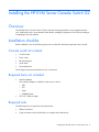
Installing the HP KVM Server Console Switch G2
Overview
The HP KVM Server Console Switch G2 ships with rack-mounting brackets for easy integration into the
rack. Stabilize the rack in a permanent location before installing the equipment. Avoid uneven loading or
overloading of the rack cabinets.
Installation checklist
Before installation, refer to the following lists to be sure that all of the listed components were received.
Console switch kit contents
•
Console switch
•
Power cords
•
Rack mounting kit
•
Serial cable
•
Documentation kit
This kit might contain extra hardware for your convenience.
Required items not included
•
Interface adapters
One interface adapter is needed for each server or device.
•
o
USB
o
PS2
o
Serial
o
HP BladeSystem
UTP CAT 5 cable or higher
Required tools
The following tools are required for some procedures:
•
Phillips screwdriver
•
Cage nut insertion tool (included with your original rack hardware kit)
Installing the HP KVM Server Console Switch G2 6
Rack-mounting the console switch
WARNING: For safe use, do not mount this product with the rear panel, which is the side of
the console switch with I/O connectors and the AC power inlet, facing downward (facing the
floor).
1.
Before installing the HP KVM Server Console Switch G2 into the rack, connect the console switch to
a power source, using the power cords provided, and power on the unit.
An activity indicator light is displayed after a few seconds. If the activity indicator light does not
display, be sure that the power is on, the power cord is connected, and the power source is valid.
2.
Choose one of the following configurations:
o
Standard-mount
o
Cantilever-mount
o
Side-mount
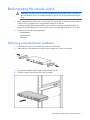
Performing a standard-mount installation
1.
Remove the four screws, two on each side, from the console switch.
2.
Attach the short 1U brackets to the console switch using the four screws you removed.
3.
If not already installed, install a cage nut behind each rear rail.
4.
Slide the console switch into the rear of the 1U product.
Installing the HP KVM Server Console Switch G2 7
5.
Secure the console switch to the rails using two M-6 screws, one on each side.
Performing a cantilever-mount installation
1.
Remove the four screws, two on each side, from the console switch.
2.
Attach the short 1U brackets to the console switch as indicated in step 2 ("Performing a standardmount installation" on page 7) of performing standard-mount installation.
3.
Install up to six cage nuts.
Installing the HP KVM Server Console Switch G2 8
4.
Secure the console switch to the rails using the appropriate number of M-6 screws.
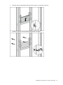
Performing a side-mount installation
1.
Remove the four screws, two on each side, from the console switch.
2.
Attach the side-mounting brackets to the console switch using the four screws you removed.
Installing the HP KVM Server Console Switch G2 9
3.
Slide the side-mounting bracket tabs into the U locations on each side of the rack.
4.
Install four cage nuts into the side-mounting bracket U locations.
Installing the HP KVM Server Console Switch G2 10
5.
Secure the console switch to the rails, using four M-6 screws, two on each side.
NOTE: Some racks enable you to use four sheet metal screws in place of M-6 screws and
cage nuts.
Console switch components
Item
Description
1
Power cord connector
2
Power switch
3
Fan
4
Serial management connector
5
Console port A USB ports (keyboard/mouse only)
6
Console port A keyboard connector
7
Console port A video connector
8
Console port A mouse connector
9
RJ-45 tiering port (designated by the letter A)
10
Server connection ports 1–8
11
Server connection ports 9–16*
Installing the HP KVM Server Console Switch G2 11
Item
Description
12
Console port B video connector
13
Console port B mouse connector
14
Console port B keyboard connector
15
Console port B USB ports (keyboard/mouse only)
16
Activity indicator light
*Additional ports are only available on the 0x2x16 console switch.
Connecting the local console switch
1.
Connect the local keyboard, video, and mouse to the console switch.
WARNING: To reduce the risk of electric shock or damage to the equipment:
• Do not disable the power cord grounding plug. The grounding plug is an important safety
feature.
• Plug the power cord into a grounded (earthed) electrical outlet that is easily accessible at all
times.
• Unplug the power cord from the power supply to disconnect power to the equipment.
• Do not route the power cord where it can be walked on or pinched by items placed against
it. Pay particular attention to the plug, electrical outlet, and the point where the cord
extends from the storage system.
2.
Plug the console switch power cord into a power source.
3.
Power on the console switch. The activity indicator light ("Console switch components" on page 11)
powers on.
4.
Power on the monitor.
The following figure shows one possible configuration for your console switch system.
Item
Description
1
Local console
2
Console switch
Installing the HP KVM Server Console Switch G2 12
Installing a PS/2 or USB interface adapter
Interface adapter overview
An interface adapter (sold separately) is required for the console switch system to function properly. An
interface adapter connects UTP CAT5 or higher cables to PS/2 or USB connections and establishes a
KVM session to a server.
NOTE: UTP CAT5 or higher cables are used throughout the examples in this guide.
Connecting the interface adapters
1.
Connect a UTP CAT5 cable or higher to the server connection port ("Console switch components" on
page 11) on the console switch.
2.
Connect the other end of the cable to the RJ-45 connector on the interface adapter.
3.
Connect the interface adapter to the appropriate connectors on the server.
4.
Repeat the preceding steps to connect additional servers to this system, if needed.
The following figure shows one possible configuration for the HP KVM Server Console Switch G2 system
with an interface adapter.
Item
Description
1
Server
2
Console switch
3
USB interface adapter
4
PS/2 interface adapter
To add server names, see Assigning names to servers (on page 36).
Installing a PS/2 or USB interface adapter 13
Cascading console switches
Compatible console switch models
This product supports only one level of cascading. Before you cascade console switches, review the
following information.
To ensure optimum equipment performance while cascading console switches, follow the proper
powering-on sequence—power on the console switches, monitor, and then servers.
CAUTION: Do not use interface adapters to cascade one HP KVM Server Console Switch G2
system with another HP KVM Server Console Switch G2 system. If interface adapters are used
to cascade these products, undesirable operations might occur.
NOTE: To perform a firmware upgrade for a cascaded HP KVM Server Console Switch G2
and all attached interface adapters, you must locally connect the keyboard, monitor, and
mouse to the cascaded HP KVM Server Console Switch G2 to access the local OSD.
HP IP Console Switch
CAUTION: Do not use an interface adapter to cascade an HP IP Console Switch with an HP
KVM Server Console Switch G2. If an interface adapter is used to cascade these products,
undesirable operations might occur.
CAUTION: While cascading console switches, be sure that the HP KVM Server Console Switch
G2 is cascaded below the HP IP Console Switch. Undesirable operations might occur if these
specific cascading sequences are not followed.
The following HP IP Console Switches can be integrated into the HP KVM Server Console Switch G2
system. Compatible HP IP Console Switch models include:
•
2 x 1 x 16 [PN AF601A]
•
4 x 1 x 16 [PN AF602A]
All HP IP Console Switches must have the latest SoftPaq firmware upgrade when cascaded.
Cascading console switches
14
Example of an HP IP Console Switch cascade configuration
Item
Description
1
Server
2
PS/2 interface adapter or USB interface adapter*
3
UTP CAT5 cable or higher
4
UTP CAT5 cable or higher
5
KVM cable
6
Main HP IP Console Switch
7
Local port
8
Cascaded HP KVM Server Console Switch
*Not shown
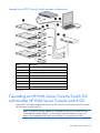
Cascading an HP KVM Server Console Switch G2
with another HP KVM Server Console Switch G2
Locate a UTP CAT5 cable or higher and connect one end to the server connection port on the cascaded
HP KVM Server Console Switch G2.
NOTE: To perform a firmware upgrade for a cascaded HP KVM Server Console Switch G2
and all attached interface adapters, you must locally connect the keyboard, monitor, and
mouse to the cascaded HP KVM Server Console Switch G2 to access the local OSD.
Cascading console switches
15
The following figure shows a HP KVM Server Console Switch G2 cascaded to another HP KVM Server
Console Switch G2. The top console switch is the main console switch. The bottom console switch is the
cascaded console switch.
CAUTION: Do not use interface adapters to cascade one HP KVM Server Console Switch G2
system with another HP KVM Server Console Switch G2 system. If interface adapters are used
to cascade these products, undesirable operations might occur.
Cascading console switches
16
Local port operation
Overview
The HP KVM Server Console Switch G2 system has at least one local port (based on the specific model)
on the rear panel ("Console switch components" on page 11) that enables the user to connect a
keyboard, monitor, and mouse to the HP KVM Server Console Switch G2 for direct access.
Use the Main dialog box ("Accessing the Main dialog box" on page 17) to view, configure, and control
servers in the HP KVM Server Console Switch G2 system.
Accessing the Main dialog box
To access the Main dialog box, choose one of the following default key sequences.
•
Print Scrn
•
Ctrl + Ctrl
To configure the following additional key sequences, see Accessing the Menu dialog box (on page 22).
•
Alt + Alt
•
Shift + Shift
NOTE: You can press the Alt, Shift, or Ctrl key twice within one second to launch the OSD.
You can use this key sequence where you see Print Scrn. For more information see, Accessing
the Menu dialog box (on page 22).
The Main dialog box appears.
Button
Description
Clear
Enables you to clear all offline interface adapters.
Local port operation 17
Button
Description
Disconnect
Enables you to disconnect the local KVM session.
Setup
Enables you to access the Setup dialog box and configure the
OSD.
Commands
Enables you to access the Commands dialog box.
Viewing servers
You can view servers by name, port, or by the unique EID embedded in each interface adapter.
Viewing the Port column
When you launch the Main dialog box ("Accessing the Main dialog box" on page 17) for the first time,
an OSD-generated port list appears.
The Port column indicates the port to which a server is connected. For example, in the following figure,
the first number represents the port number of the first console switch and the second number represents
the port number of the cascaded console switch port to which the server is connected.
Port number
of the first
console
switch
Port number of
the cascaded
console switch
16
01
The server is connected to port 01 of the 2 x 8 HP
KVM Server Console Switch, and that HP KVM
Server Console Switch is cascaded from port 16 of
the first HP KVM Server Console Switch.
14
02
The server is connected to port 02 of the 2 x 16 HP
KVM Server Console Switch, and that HP KVM
Server Console Switch is cascaded from port 14 of
the first HP KVM Server Console Switch.
Server status
icon displayed
Description
04
The server is connected to the first console switch
and the interface adapter is not connected, or the
server is powered off.
05
The server is connected to the first console switch
and is active.
Local port operation 18
Viewing the Server Status column
The status of each server in the HP KVM Server Console Switch system is indicated by the icons in the
right column of the Main dialog box ("Accessing the Main dialog box" on page 17).
Item
Description
The interface adapter is connected directly, cascaded through an HP KVM Server Console
Switch, or powered on.
The interface adapter is not connected or the server is powered off.
The interface adapter is being upgraded.
This symbol identifies the port to which the console switch is connected.
This symbol identifies the port to which you are connected and viewing.
This symbol identifies another active port to which you are not connected.
Selecting servers
From the Main dialog box ("Accessing the Main dialog box" on page 17), you can select specific
servers. When you select a new server, the console switch reconfigures the KVM to the setting for the
selected server.
•
Double-click the server Name, EID, or Port.
•
If the display order of the server list is by Port (the Port button is clicked), enter the port number and
press the Enter key.
•
If the display order of the server list is by Name or EID number, enter the first few letters of the name
of the server or the EID number to establish it as unique, and then press the Enter key.
NOTE: The EID is an electronic identification number, found on the interface adapter cable
label, automatically assigned to the interface adapter.
Soft switching
Soft switching is the ability to switch servers using a hotkey sequence. You can soft switch to a server by
pressing the Print Scrn key, entering the first few characters of the server's name or port number, and
pressing the Enter key.
Soft switching to a server
If the display order of your server list is by port, press the Print Scrn key, select the Port, and press the
Enter key.
If the display order of your server list is by name, press the Print Scrn key, select the Name, and press the
Enter key.
Local port operation 19
Configuring switches for soft switching
1.
From the Main dialog box ("Accessing the Main dialog box" on page 17), click Setup>Menu. The
Menu dialog box appears.
2.
For Screen Delay Time, enter the number of seconds of delay desired before the Main dialog box
displays after the Print Scrn key is pressed.
3.
Click OK to save settings.
Soft switching to a previous server
Press the Print Scrn key, then press the Backspace key. This key combination toggles between the previous
and current connection.
Disconnecting from a server
Press the Print Scrn key and press the Alt+0 keys, or click Disconnect.
This leaves no server selected and the console switch is in a free state. The status flag ("Controlling the
status flag" on page 23) on the OSD appears as Free.
Using basic OSD navigation keys
Keystroke
Description
Print Scrn
Opens the OSD Main dialog box. Press the Print Scrn key twice to send the
Print Scrn keystroke to the currently selected device.
F1
Opens the Help screen for the current dialog box.
Esc
Closes the current dialog box without saving changes and returns to the
previous dialog box. In the Main dialog box, it closes the OSD and returns to
the selected server. In a message box, it closes the pop-up box and returns to
the current dialog box.
Alt
Opens dialog boxes, selects options, and executes actions, when used in
combination with the other keys.
Alt + X
Closes the current dialog box and returns to the previous dialog box.
Alt + 0
Selects the OK button and returns to the previous dialog box.
Enter
Completes the console switch operation in the Main dialog box and exits the
OSD.
Single-click, Enter
Selects the text, in a text box, for editing and enables the left and right arrow
keys to move the cursor. Press the Enter key again to quit Edit mode.
Print Scrn, Backspace
Toggles back to the previous selection if no other keystrokes have been
entered.
Print Scrn, Alt + 0
Disengages the user immediately from a server–no server is selected. Status
Flag displays Free. (This only applies to the 0 on the keyboard, not the
keypad.)
Print Scrn, Pause
Activates the Screen Saver mode immediately and prevents access to that
particular console if it is password protected.
Up or Down arrows
Moves the cursor from line to line.
Local port operation 20
Keystroke
Description
Right or Left arrows
Moves the cursor between columns. When editing a text box, these keys move
the cursor within the column.
Page Up or Page Down
Pages up and down through Name and Port lists.
Ctrl + Ctrl, Shift + Shift
Activates OSD.
or Alt + Alt
Home or End
Moves the cursor to the top or bottom of a list.
Backspace
Erases characters in a text box.
Delete
Deletes current selection in the Scan dialog box or characters in a text box.
Shift, Delete
Deletes from current selection to all lines below it when editing a scan list.
Numbers
Adds numbers from the keyboard or keypad.
Caps Lock
Disables the user. (Use the Shift key to change case.)
Configuring the Setup dialog box
You can configure the console switch and manage routine tasks for your servers from the Setup dialog
box ("Accessing the Setup dialog box" on page 21) within the OSD.
Accessing the Setup dialog box
From the Main dialog box ("Accessing the Main dialog box" on page 17), click Setup. The Setup dialog
box appears.
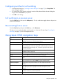
Managing routine tasks for servers
Button
Function
Menu
Changes the server listing between numerically by port or EID number and
alphabetically by name. After you press Print Scrn, changes the delay time before
the Main dialog box appears.
Flag
Changes the display, timing, color, and location of the status flag.
Local port operation 21
Button
Function
Broadcast
Controls multiple servers simultaneously through keyboard and mouse actions.
Scan
Sets up custom scan patters for up to 16 servers.
Security
Sets password to restrict server access. A valid password must be alphanumeric and
contain a minimum of five characters and a maximum of 15 characters. Permitted
characters are case sensitive and can consist of A–Z, 0–9, spaces and hyphens.
Enables the Screen Saver mode.
Switch
Changes the Switch mode to preemptive or cooperative.
Keyboard
Changes the keyboard country code reported by the interface adapter if queried.
Language
Enables a user to change the language displayed in the OSD. Changes the
language for help text, key mapping, and all screens.
Devices
Identifies device types attached to the console switch, including servers and other
legacy console switches. You can also modify the type of legacy console switches.
Names
Enables you to name the interface adapter.
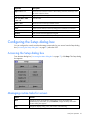
Changing the display behavior
From the Menu dialog box ("Accessing the Menu dialog box" on page 22), the display order of servers,
HP KVM Server Console Switch G2 connection mode, and a time to delay display of the OSD after
pressing the Print Scrn key can be changed. The display order setting alters how servers display in several
screens, including the Main, Devices, and Broadcast dialog boxes.
Accessing the Menu dialog box
To access the Menu dialog from the Main dialog box ("Accessing the Main dialog box" on page 17),
click Setup>Menu. The Menu dialog box appears.
Selecting the display order of servers
1.
From the Menu dialog box ("Accessing the Menu dialog box" on page 22), select Name to display
servers alphabetically by name.
Local port operation 22
-orSelect EID to display servers numerically by interface adapter ID number.
-orSelect Port to display servers numerically by port number.
2.
Click OK to save settings.
-orClick X to exit, or press the Esc key to exit without saving settings.
Selecting and setting the OSD hot key command
1.
Select the desired hot key sequence.
Clearing all boxes leaves the Print Screen as the default option.
2.
Choose one of the following options:
o
Click OK to save settings
o
Click X or press the Esc key to exit without saving settings.
Setting a screen delay time
Setting a time to delay the display of the OSD enables you to complete a soft switch ("Soft switching" on
page 19) without displaying the OSD. It is strongly recommended to leave the number of seconds (0-9)
the OSD is delayed to the default (0).
1.
From the Main dialog box ("Accessing the Main dialog box" on page 17), enter the number of
seconds (0–9) the OSD is delayed after pressing the Print Scrn key. Entering 0 instantly displays the
OSD with no delay.
2.
Click OK to save settings.
-orClick X to exit, or press the Esc key to exit without saving settings.
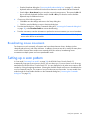
Controlling the status flag
The status flag appears on the desktop and shows the Name or EID number of the selected server or the
status of a particular port. Use the Flag dialog box ("Accessing the Flag dialog box" on page 24) to
change the flag display by server name or EID number or to change the flag color, opacity, display time,
and location on the desktop.
Flag
Description
Flag type by name
Flag type by EID number
Flag indicating that the user has been disconnected from all
systems
Flag indicating that the broadcast is activated
Flag indicating that the user is in share mode
Local port operation 23
Flag
Description
Control used to set flag position
Accessing the Flag dialog box
From the Main dialog box ("Accessing the Main dialog box" on page 17), click Setup>Flag. The Flag
dialog box appears.
Displaying the status flag
1.
From the Flag dialog box ("Accessing the Flag dialog box" on page 24), select Name or EID to
determine what information appears.
2.
Select Displayed to show the flag constantly, or select Timed to display the flag for only five seconds
after soft switching.
3.
Select a flag color in Display Color.
4.
In the Display Mode, select Opaque for a solid-color flag or Transparent to see the desktop through
the flag.
5.
Position the status flag on the desktop:
a. Click Set Position to gain access to the Position Flag screen.
b. Left-click and hold the title bar and drag to the desired location.
c.
6.
Right-click to return to the Flag dialog box.
Choose one of the following options:
o
Click OK to save settings.
o
Click X to exit, or press the Esc key to exit without saving settings.
NOTE: Changes made to the position flag are not saved until you click OK in the Flag dialog
box ("Accessing the Flag dialog box" on page 24).
Local port operation 24
Broadcasting to servers
Analog users can simultaneously control more than one server in a system to be sure that all selected
servers receive identical input. For each server receiving the broadcast, you can choose to broadcast
keystrokes and mouse movements independently.
NOTE: During broadcast, any users connected to a broadcast server will be disconnected and
unable to access any servers.
NOTE: You can broadcast to only one server per Expansion Module connection.
Accessing the Broadcast dialog box
From the Main dialog box ("Accessing the Main dialog box" on page 17), click Setup>Broadcast. The
Broadcast dialog box appears.
Activating the Broadcast dialog box
To activate broadcasting, from the Commands dialog box ("Accessing the Commands dialog box" on
page 38), select Broadcast Enable.
To deactivate broadcasting, from the Commands dialog box ("Accessing the Commands dialog box" on
page 38), clear Broadcast Enable.
Broadcasting keystrokes
The keyboard statistics must be identical for all servers receiving a broadcast to interpret keystrokes
identically. Specifically, the Caps Lock and Num Lock modes must be the same on all keyboards. While
the HP KVM Server Console Switch G2 attempts to send keystrokes to the selected servers simultaneously,
some servers can inhibit and thereby delay the transmission.
Broadcasting selected servers
1.
Select the keyboard and mouse using one of the following options:
Local port operation 25
2.
o
From the Broadcast dialog box ("Accessing the Broadcast dialog box" on page 25), select the
keyboard and mouse checkboxes for the servers that are to receive the broadcast commands.
o
Press the Up or Down Arrow keys to move the cursor to the target server. Then press the Alt + K
keys to select the keyboard checkbox and/or the Alt + M keys to select the mouse checkbox.
Repeat the step for additional servers.
Choose one of the following options:
o
Click OK to save the settings and return to the Setup dialog box.
o
Click X or press the Esc key to return to the Main dialog box.
3.
From the Main dialog box, click the Commands dialog box ("Accessing the Commands dialog box"
on page 38), select Broadcast Enable to activate broadcasting.
4.
From the user station, enter the information or perform the mouse movements you want to broadcast.
NOTE: Access by a second local user is disabled when broadcast mode is enabled. Only
servers within the list are accessible.
Broadcasting mouse movements
For the mouse to work accurately, all systems must have identical mouse drivers, desktops (such as
identically placed icons), and video resolutions. In addition, the mouse must be in exactly the same place
on all screens. Because these conditions are extremely difficult to achieve, broadcasting mouse
movements to multiple systems can have unpredictable results.
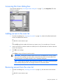
Setting up a scan pattern
In Scan mode ("Activating Scan mode" on page 28), the HP KVM Server Console Switch G2
automatically scans port to port (server to server).You can select up to 16 servers from a list of all servers
attached to the HP KVM Server Console Switch G2. You can display the list by either server name or EID
number by clicking the appropriate button. Selecting the checkbox beside each server to be added to the
scan list creates the scan list. The creation of a scan list does not start Scan mode. You must enable Scan
mode through the Scan Enable checkbox on the Commands dialog box ("Accessing the Commands
dialog box" on page 38).
Local port operation 26
Accessing the Scan dialog box
From the Main dialog box ("Accessing the Main dialog box" on page 17), click Setup>Scan. The Scan
dialog box appears.
Adding servers to the scan list
1.
From the Scan dialog box ("Activating Scan mode" on page 28), select the checkbox beside each
server to be added to the scan list.
-orDouble-click a server name or port.
-orPress the Alt key plus the number of the server you want to scan. You can select up to 16 servers.
2.
In the Scan Time box, enter the number of seconds (from 3 to 99) before the scan moves to the next
server in the sequence.
3.
Click OK to save settings.
-orClick Clear to remove all servers from the scan list.
IMPORTANT: Selecting the checkbox beside each server to be added to the scan list creates
the scan list. The creation of a scan list does not start the Scan mode. You must enable Scan
mode through the Scan Enable checkbox on the Commands dialog box.
NOTE: Servers will be scanned in the order they are selected. If you remove a server from the
Device Modify dialog box later, the change can affect a custom scan pattern.
Removing servers from the scan list
1.
From the Scan dialog box ("Activating Scan mode" on page 28), click the server to be removed.
-orDouble-click a server name or port.
-or-
Local port operation 27
Click Clear to remove all servers from the scan list.
2.
Click OK to save settings.
Activating Scan mode
1.
From the Commands dialog box ("Accessing the Commands dialog box" on page 38), select Scan
Enable.
2.
Click X to close the Commands dialog box.
NOTE: The scanning begins as soon as you click Scan.
Deactivating Scan mode
If the OSD is open, select a server.
-orIf the OSD is not open, move the mouse or press any key on the keyboard. Scanning stops at the currently
selected server.
-orFrom the Commands dialog box ("Accessing the Commands dialog box" on page 38), deselect Scan
Enable. Any active connections on the local port are disconnected.
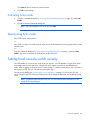
Setting local console switch security
The OSD enables you to set security on the local port consoles. You can establish a Screen Saver mode
that engages after the HP KVM Server Console Switch G2 remains unused for a user-definable time
delay. When engaged, the HP KVM Server Console Switch G2 remains locked until any key is pressed or
the mouse is moved. Then you can enter the password to log in.
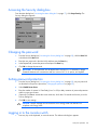
Use the Security dialog box ("Accessing the Security dialog box" on page 29) to lock your HP KVM
Server Console Switch G2 with password protection, set or change the password, and enable the screen
saver.
NOTE: If a password has been previously set, you must enter the password before you can
access the Security dialog box.
Local port operation 28
Accessing the Security dialog box
From the Main dialog box ("Accessing the Main dialog box" on page 17), click Setup>Security. The
Security dialog box appears.
Changing the password
1.
From the Security dialog box ("Accessing the Security dialog box" on page 29), click the New field
or double-click the New field.
2.
Enter the new password in the New field, and then press the Enter key.
3.
In the Repeat field, re-enter the password and press the Enter key.
4.
Click OK to change the password.
IMPORTANT: A valid password must be alphanumeric and be 5 to 15 characters in length.
Permitted characters are case-sensitive and can consist of A–Z, 0–9, spaces, and hyphens.
Setting password protection
1.
From the Security dialog box ("Accessing the Security dialog box" on page 29), set your password
as described in the previous procedure ("Changing the password" on page 29).
2.
Select Enable Screen Saver.
3.
Enter the number of minutes for Time Delay (from 1 to 99) to delay activation of password protection
and the screen saver feature.
4.
(Optional) Click Test to activate the screen saver test, which lasts 10 seconds and returns you to the
Security dialog box.
5.
Click OK to save settings.
CAUTION: Monitor damage can result from the use of energy mode with monitors not
compliant with Energy Star®.
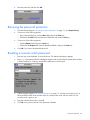
Logging in to the console switch
1.
Press any key on the keyboard, or move the mouse. The Authorize dialog box appears.
Local port operation 29
2.
Enter the password, and then click OK.
Removing the password protection
1.
From the Main dialog box ("Accessing the Main dialog box" on page 17), click Setup>Security.
2.
Choose one of the following options:
3.
4.
o
In the Security dialog box, click the New field and press the Enter key.
o
Double-click the New field, leave the New field blank, and press the Enter key.
Choose one of the following options:
o
Click the Repeat field and press the Enter key.
o
Double-click the Repeat field, leave the Repeat field blank, and press the Enter key.
Click OK if you want to eliminate the password.
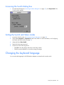
Resetting a console switch password
1.
Press any key on the keyboard, or move the mouse. The Authorize dialog box appears.
2.
Enter help in the password field. A dialog box appears with an HP technical support phone number
(1-800-474-6836), a 16-bit key, and the EID number of the console switch.
3.
Call HP technical support ("HP contact information" on page 47). Give the service person your 16bit key and EID number of the console switch. A one-time unlock code, which is specific to your
console switch, is given to you.
4.
Enter the one-time unlock code in the field.
5.
Click OK. Your previous console switch password is deleted.
Local port operation 30
Exiting screen saver mode
To exit the Screen Saver mode, press any key or move the mouse. The Main dialog box ("Accessing the
Main dialog box" on page 17) is displayed.
Activating Screen Saver mode without password protection
1.
If your HP KVM Server Console Switch G2 does not require a password to gain access to the
Security dialog box ("Accessing the Security dialog box" on page 29), proceed to step 2.
-orIf your HP KVM Server Console Switch G2 is password protected, refer to the Deactivating the
Screen Saver (on page 31) section, then go to step 2.
2.
Select Enable Screen Saver.
3.
Enter the number of minutes for Inactivity Time (1 to 99) to delay activation of the screen saver.
4.
(Optional) Click Test to activate the screen saver test, which lasts 10 seconds, then returns you to the
Security dialog box.
5.
Click OK to save settings.
CAUTION: Monitor damage can result from the use of energy mode with monitors not
compliant with Energy Star®.
NOTE: No server is selected after the activation of the screen saver mode disconnects the user
from a server. The status flag displays Free.
Deactivating the screen saver
1.
From the Security dialog box ("Accessing the Security dialog box" on page 29), deselect Enable
Screen Saver.
2.
Click OK to save settings.
To immediately activate the screen saver, press the Print Scrn key, and then press the Pause key. This
command only works when the user is connected to a server.
Configuring the Switch and Share modes
The Switch window can be used to set one of the following switch modes:
•
Preemptive (default setting)—Enables any user to select any server at any time; a request from
another user disconnects the current user without warning.
•
Cooperative—Maintains the current user connection; the current user will not be disconnected if
another user requests connection.
You can also enable or disable Share mode and specify a time-out period from the Switch window. Share
mode enables two users to access a primary server.
Local port operation 31
Accessing the Switch dialog box
1.
From the Main dialog box ("Accessing the Main dialog box" on page 17), click Setup>Switch. The
Switch window appears.
Setting the Switch and Share modes
1.
Access the Switch window ("Accessing the Switch dialog box" on page 32).
2.
Select either Preemptive or Cooperative as the Switch mode. For more information, see Configuring
the Switch and Share modes (on page 31).
3.
(Optional) Select Share Enable.
4.
Specify the share time-out period.
5.
Choose one of the following options:
o
Click OK to save the settings and return to the Setup window.
o
Click X or press the Esc key to exit without saving the settings.
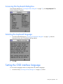
Changing the keyboard language
You can select the language for all USB Interface Adapters connected to the console switch.
Local port operation 32
Accessing the Keyboard dialog box
From the Main dialog box ("Accessing the Main dialog box" on page 17), click Setup>Keyboard. The
Keyboard dialog box appears.
Selecting the keyboard language
1.
From the Keyboard dialog box ("Accessing the Keyboard dialog box" on page 33), select the
keyboard country code. A Keyboard Warning appears.
2.
Click OK.
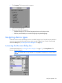
Setting the OSD interface language
You can use the Language window to configure the OSD interface languages.
1.
Access the Setup ("Accessing the Setup dialog box" on page 21) window.
Local port operation 33
2.
Click Language. The Language window appears.
3.
Select the desired language.
4.
Choose one of the following options:
o
Click OK to change the OSD interface language and return to the Setup window.
o
Click X or press the Esc key to exit without changing the keyboard language.
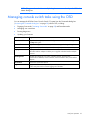
Assigning device types
While the console switch automatically discovers cascaded Compaq Server Console Switches attached to
your unit, you must specify the number of ports on the cascade Compaq Server Console Switch through
the Devices dialog box ("Accessing the Devices dialog box" on page 34).
Accessing the Devices dialog box
From the Main dialog box ("Accessing the Main dialog box" on page 17), click Setup>Devices. The
Devices dialog box appears.
NOTE: The Modify button is only available if a configurable Compaq Server Console Switch is
selected.
Local port operation 34
When the HP KVM Server Console Switch G2 discovers a cascaded HP KVM Server Console Switch G2,
the port numbering changes automatically to accommodate each server. For example, if the HP KVM
Server Console Switch G2 is connected to port 02, the switch port is listed as 02, and each server under
it is numbered sequentially 02-01, 02-02, and so on.
However, when a HP KVM Server Console Switch G2 discovers a cascaded Compaq Server Console
Switch, you must select the number of ports on the Compaq Server Console Switch through the Device
Modify dialog box.
Modifying device types
1.
From the Devices dialog box ("Accessing the Devices dialog box" on page 34), select the Port
number.
2.
Click Modify. The Device Modify dialog box appears.
3.
Select the number of ports supported by the cascaded Compaq Server Console Switch. If the number
of ports on the tiered switch is not listed, click Other and enter a port number between 4 and 24.
4.
Click OK.
5.
Repeat the previous steps for each port the user wants to assign a device type.
6.
Choose one of the following options:
o
Click OK in the Devices dialog box to save settings.
o
Click X to exit, or press the Esc key to exit without saving settings.
NOTE: Changes made in the Device Modify dialog box are not saved until you click OK in the
Devices dialog box.
Accessing the Names dialog box
From the Main dialog box ("Accessing the Main dialog box" on page 17), click Setup>Names. The
Names dialog box appears.
NOTE: If the server list has changed since it was last displayed, the mouse cursor turns into an
hourglass as the list automatically updates. No mouse or keyboard input is accepted until the
list update is complete.
Local port operation 35
Assigning server names
Use the Names dialog box ("Accessing the Names dialog box" on page 35) to identify individual servers
or serial devices by name rather than by port number. The Names list is always sorted by port order, and
the names are stored in the Interface Adapter. If you move the Interface Adapter or server to another
switch port, the HP KVM Server Console Switch G2 recognizes the names and configurations.
Assigning names to servers
1.
From the Names dialog box ("Accessing the Names dialog box" on page 35), select the name or
port number and click Modify. The Name Modify dialog box appears.
2.
In the New Name field, enter a name. Names can be 1 to 15 characters in length. Permitted
characters are case-sensitive and can consist of A–Z, 0–9, spaces, and hyphens.
3.
Click OK to transfer the new name to the Names dialog box.
4.
Repeat steps the previous steps for each server in the system.
5.
Choose one of the following options:
o
Click OK to save settings.
o
Click X to exit, or press the Esc key to exit without saving settings.
Local port operation 36
NOTE: Changes made in the Name Modify dialog box are not saved until you click OK in the
Names dialog box.
Managing console switch tasks using the OSD
You can manage the HP KVM Server Console Switch G2 system from the Commands dialog box
("Accessing the Commands dialog box" on page 38) with the OSD, including:
•
Engaging Scan mode ("Activating Scan mode" on page 28) and Broadcast mode
•
Managing user connections
•
Running diagnostics
•
Updating your firmware
Feature
Purpose
Broadcast Enable
Begins broadcasting to your servers. Configures a server list for broadcasting under
the Setup dialog box.
Scan Enable
Begins scanning your servers. Sets up a list for scanning in the Setup dialog box.
IA Status
Upgrades multiple interface adapters simultaneously.
Display Versions
Displays version information for the console switch, and firmware information for
individual interface adapters. Enables you to upgrade individual interface adapter
firmware.
Run Diagnostics
Validates the integrity of your system, including memory, firmware CRC,
communication interfaces, switch controllers, local and remote video, and interface
adapters.
Device Reset
Resets local console PS2 devices
Log Out
Logs you out of the OSD. If password protection is enabled, you must enter the
screen saver password to continue logging out of the OSD.
Local port operation 37
Accessing the Commands dialog box
From the Main dialog box ("Accessing the Main dialog box" on page 17), click Commands. The
Commands dialog box appears.
NOTE: The Log Out button is only active if a password is set. For more information on setting
a password, see Setting password protection (on page 29).
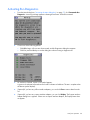
Running system diagnostics
Clicking Run Diagnostics ("Activating Run Diagnostics" on page 39) runs a command to check the main
board functions subsystems (memory, intra-board communications, HP KVM Server Console Switch G2
control, and the video channels) for each system controller.
Test
Description
Memory Test
Reports the condition of the main board RAM. This indicator displays the results of
the memory tests performed at system reboot.
Firmware CRCs
Validates the current firmware images stored in the system FLASH by comparing a
CRC value on each image and comparing those results to the expected values.
Comm Interfaces
Verifies the intra-board communication subsystems are accessible and functional by
querying the communications controller and performing basic register level tests.
Switch Controller
Verifies the switch matrix controller is accessible and functional by querying the
switch matrix controller and performing basic register level tests.
Local Video
Verifies that all the video channel subsystems are accessible, functional, and
performing basic register level tests.
Online IAs
Indicates the total number of currently connected and powered interface adapters.
Offline IAs
Indicates the number of interface adapters that have been connected successfully in
the past and are powered down.
Suspect IAs
Indicates the number of interface adapters that have been detected but are either
unavailable for connection or have dropped packets during the ping tests.
Local port operation 38
Activating Run Diagnostics
1.
From the Main dialog box ("Accessing the Main dialog box" on page 17), click Commands>Run
Diagnostics. A warning message appears indicating that all users will be disconnected.
2.
Choose one of the following options:
3.
o
Click OK to begin. All users are disconnected, and the Diagnostics dialog box appears.
o
Click X or press the Esc key to exit the dialog box without running a diagnostic test.
As each test is finished, a pass or fail symbol appears.
A green circle indicates a passed test and a red X indicates a failed test. The test is complete when
the last test symbol displays.
4.
(Optional) If you have any offline interface adapters, you can click Clear to remove them from the
list.
5.
(Optional) If you have any suspect interface adapters, you can click Display. The Suspect interface
adapter dialog box is appears. If there are no suspect interface adapters, the Display button does
not appear.
Local port operation 39
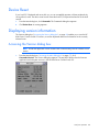
Device Reset
If your local PS/2 keyboard and mouse lock up, you can re-establish operation of these peripherals by
issuing a device reset. The device reset function resets the local PS/2 keyboard and mouse for the local
console.
1.
From the Main dialog box, click Commands. The Commands dialog box appears.
2.
Click Device Reset. A warning appears.
Displaying version information
The Versions dialog box ("Accessing the Version dialog box" on page 40) enables you to view the HP
KVM Server Console Switch G2 versions, as well as keyboard and mouse information for the currently
selected server.
Accessing the Version dialog box
NOTE: Provide the application version number when communicating with HP customer service
centers.
1.
From the Main dialog box ("Accessing the Main dialog box" on page 17), click
Commands>Versions. The Version dialog box appears. The top half of the box lists the firmware
application and subsystem versions in the HP KVM Server Console Switch G2.
Local port operation 40
Upgrading the firmware
Upgrading the console switch firmware
1.
Connect the serial cable to the serial port on the PC (must be running Microsoft® Windows®) and to
the serial port ("Console switch components" on page 11) on the rear panel of the HP KVM Server
Console Switch G2.
2.
Go to the folder where the firmware files are saved and run the ApplianceUpDate.exe file.
NOTE: The .bin files must be in the same folder as the ApplianceUpDate.exe file.
3.
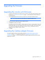
Enter the COM port number being used to load the firmware.
4.
Click Load. The update process begins.
The update process has three updates—Loading Application Firmware, Loading Graphics Chip, and
Loading System Data. You see a progress bar for each of those three updates. The firmware update
is not done until all updates have been loaded. When the firmware is updated, the following
message, indicating "Update Complete" appears.
5.
Click Done.
Upgrading the interface adapter firmware
The Interface Adapter firmware can be loaded individually ("Loading interface adapter firmware
individually" on page 42), or upgraded simultaneously ("Upgrading interface adapter firmware
simultaneously" on page 42). The servers attached to the interface adapters must be powered on while
upgrading the firmware.
Upgrading the firmware 41
Upgrading interface adapter firmware simultaneously
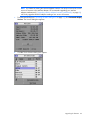
1.
From the Main dialog box ("Accessing the Main dialog box" on page 17), click Commands>IA
Status. The IA Status dialog box appears.
2.
Select PS/2, USB, or Serial, and then click Upgrade. The IA Upgrade dialog box appears.
NOTE: You can configure automatic upgrades of all interface adapters connected to the
console switch by checking the Auto Upgrade box in the IA Status window.
3.
Click OK to save settings.
4.
Press the Esc key to return to the Main dialog box ("Accessing the Main dialog box" on page 17).
The OSD indicators appear yellow while the upgrade is in progress. The indicators change to red
and then to green when the upgrade is complete.
NOTE: Wait until the OSD indicators are displayed as green before continuing.
Loading interface adapter firmware individually
Upgrading the firmware 42
NOTE: This method of loading the interface adapter firmware will always overwrite the current
version of firmware in the interface adapter. HP recommends upgrading your interface
adapters simultaneously ("Upgrading interface adapter firmware simultaneously" on page 42),
which only upgrades interface adapters needing a new version of firmware.
1.
From the Main dialog box ("Accessing the Main dialog box" on page 17), click Commands>Display
Versions. The Version dialog box appears.
2.
Click IA. The IA Selection dialog box appears.
Upgrading the firmware 43
3.
Select the individual interface adapter, and click Version. The IA Version dialog box appears.
4.
Click Load Firmware.
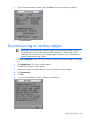
Decommissioning an interface adapter
IMPORTANT: Decommissioning an interface adapter restores the factory defaults, removing
any assigned server names and resetting any other configurations, while leaving the EID
unchanged. After decommissioning an interface adapter, reboot the server connected to the
interface adapter before using it again.
1.
Access the Commands window. For more information, see Accessing the Main dialog box (on page
17).
2.
Click Display Version. The Version window appears.
3.
Click IA. The IA Selection window appears.
4.
Select a server that is connected to the rack console switch with an interface adapter.
5.
Click Decommission.
6.
Click OK.
7.
To close the Target Selection window, click X or press the Esc key.
Upgrading the firmware 44
Troubleshooting
Connection length requirements
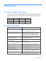
The HP KVM Server Console Switch G2 offers optimum video performance when the distance between
the server and console switch is 15 m (50 ft) or less (1280 x 1024 at 75 Hz). The system is capable of
operation at distances up to 30 m (100 ft) at reduced video resolutions (800 x 640 at 60 Hz, worst
case).
Distance
1280 x 1024
1024 x 768
800 x 640
15.24 m (50 ft)
X
X
X
22.86 m (75 ft)
—
—
X
30.48 m (100 ft)
—
—
X
Troubleshooting table
Problem
Solution
The local user cannot view the OSD copyright
notice.
•
Be sure that the power source is valid.
•
Be sure that the cables are connected properly.
•
Be sure that the monitor is valid.
The OSD copyright notice is distorted.
The local user cannot view the OSD flag.
Preview the preferences in the OSD to determine if the
local port display has been disabled or set to time out. If
the preferences are set to not display the OSD flag or to
have the flag time out, then the OSD flag does not appear.
The local user cannot activate or view the OSD,
and the OSD flag disappears.
Be sure that the local port keyboard is connected properly
and that the keyboard is valid.
The OSD is distorted or not readable on the
local port video display.
Be sure that the monitor supports the refresh rate to which
target server is set.
The activity indicator light ("Console switch
components" on page 11) does not display
when the console switch is powered on.
•
Be sure that the console switch is powered on and that
the power source is valid.
•
Be sure that the cables are connected properly
The system does not recognize the HP IP Console All HP IP Console Switches must be upgraded with
Switch.
firmware version 3.0.0 or later.
The console switch system is inaccessible
because the password is lost.
Call the HP Customer Support Center ("HP contact
information" on page 47).
Video displays are all green or red.
•
Check the UTP CAT5 cable for breaks or bad crimps.
•
Check the VGA connection for bent pins.
The screen saver does not turn on.
Be sure to click OK to confirm the screen saver selection.
Click X or press the Esc key to cancel the command.
Troubleshooting 45
Problem
Solution
When connecting a serial interface adapter to a
server running Linux Red Hat or SLES, the
numeric keypad keys on a PC keyboard do not
map to VT100 emulation under the Linux shell.
Using the numeric keypad with the vi text editor
causes function characters to appear instead of
numbers.
•
Use the "printenv" command to show the TERM
assigned under Linux. It can be matched appropriately
with other termcap entries by editing the profile or
setting the TERM = "ansi". For PC keyboards, ANSI is
the most compatible emulation.
•
Edit you /etc/inittab as:
s0:2345:respawn:sbin/agetty -h ttyS0
115200, 9600 ansi
Where ttyS0 is the serial device name where the serial
interface adapter is connected. Then as a shell prompt,
enter init q, or reboot the system.
The video resolution is distorted.
For more information, see the Connection Length Table
("Connection length requirements" on page 45).
Troubleshooting 46
Technical support
Before you contact HP
Be sure to have the following information available before you call HP:
•
Technical support registration number (if applicable)
•
Product serial number
•
Product model name and number
•
Product identification number
•
Applicable error messages
•
Add-on boards or hardware
•
Third-party hardware or software
•
Operating system type and revision level
HP contact information
For the name of the nearest HP authorized reseller:
•
See the Contact HP worldwide (in English) webpage
(http://welcome.hp.com/country/us/en/wwcontact.html).
For HP technical support:
•
•
In the United States, for contact options see the Contact HP United States webpage
(http://welcome.hp.com/country/us/en/contact_us.html). To contact HP by phone:
o
Call 1-800-HP-INVENT (1-800-474-6836). This service is available 24 hours a day, 7 days a
week. For continuous quality improvement, calls may be recorded or monitored.
o
If you have purchased a Care Pack (service upgrade), call 1-800-633-3600. For more
information about Care Packs, refer to the HP website (http://www.hp.com/hps).
In other locations, see the Contact HP worldwide (in English) webpage
(http://welcome.hp.com/country/us/en/wwcontact.html).
Technical support 47
Regulatory compliance notices
Regulatory compliance identification numbers
For the purpose of regulatory compliance certifications and identification, this product has been assigned
a unique regulatory model number. The regulatory model number can be found on the product nameplate
label, along with all required approval markings and information. When requesting compliance
information for this product, always refer to this regulatory model number. The regulatory model number is
not the marketing name or model number of the product.
Federal Communications Commission notice
Part 15 of the Federal Communications Commission (FCC) Rules and Regulations has established Radio
Frequency (RF) emission limits to provide an interference-free radio frequency spectrum. Many electronic
devices, including computers, generate RF energy incidental to their intended function and are, therefore,
covered by these rules. These rules place computers and related peripheral devices into two classes, A
and B, depending upon their intended installation. Class A devices are those that may reasonably be
expected to be installed in a business or commercial environment. Class B devices are those that may
reasonably be expected to be installed in a residential environment (for example, personal computers).
The FCC requires devices in both classes to bear a label indicating the interference potential of the device
as well as additional operating instructions for the user.
FCC rating label
The FCC rating label on the device shows the classification (A or B) of the equipment. Class B devices
have an FCC logo or ID on the label. Class A devices do not have an FCC logo or ID on the label. After
you determine the class of the device, refer to the corresponding statement.
Class A equipment
This equipment has been tested and found to comply with the limits for a Class A digital device, pursuant
to Part 15 of the FCC Rules. These limits are designed to provide reasonable protection against harmful
interference when the equipment is operated in a commercial environment. This equipment generates,
uses, and can radiate radio frequency energy and, if not installed and used in accordance with the
instructions, may cause harmful interference to radio communications. Operation of this equipment in a
residential area is likely to cause harmful interference, in which case the user will be required to correct
the interference at personal expense.
Class B equipment
This equipment has been tested and found to comply with the limits for a Class B digital device, pursuant
to Part 15 of the FCC Rules. These limits are designed to provide reasonable protection against harmful
interference in a residential installation. This equipment generates, uses, and can radiate radio frequency
Regulatory compliance notices
48
energy and, if not installed and used in accordance with the instructions, may cause harmful interference
to radio communications. However, there is no guarantee that interference will not occur in a particular
installation. If this equipment does cause harmful interference to radio or television reception, which can
be determined by turning the equipment off and on, the user is encouraged to try to correct the
interference by one or more of the following measures:
•
Reorient or relocate the receiving antenna.
•
Increase the separation between the equipment and receiver.
•
Connect the equipment into an outlet on a circuit that is different from that to which the receiver is
connected.
•
Consult the dealer or an experienced radio or television technician for help.
Declaration of conformity for products marked with
the FCC logo, United States only
This device complies with Part 15 of the FCC Rules. Operation is subject to the following two conditions:
(1) this device may not cause harmful interference, and (2) this device must accept any interference
received, including interference that may cause undesired operation.
For questions regarding this product, contact us by mail or telephone:
•
Hewlett-Packard Company
P. O. Box 692000, Mail Stop 530113
Houston, Texas 77269-2000
•
1-800-HP-INVENT (1-800-474-6836). (For continuous quality improvement, calls may be recorded
or monitored.)
For questions regarding this FCC declaration, contact us by mail or telephone:
•
Hewlett-Packard Company
P. O. Box 692000, Mail Stop 510101
Houston, Texas 77269-2000
•
1281-514-3333
To identify this product, refer to the part, series, or model number found on the product.
Modifications
The FCC requires the user to be notified that any changes or modifications made to this device that are
not expressly approved by Hewlett-Packard Company may void the user’s authority to operate the
equipment.
Cables
Connections to this device must be made with shielded cables with metallic RFI/EMI connector hoods in
order to maintain compliance with FCC Rules and Regulations.
Regulatory compliance notices
49
Canadian notice (Avis Canadien)
Class A equipment
This Class A digital apparatus meets all requirements of the Canadian Interference-Causing Equipment
Regulations.
Cet appareil numérique de la classe A respecte toutes les exigences du Règlement sur le matériel
brouilleur du Canada.
Class B equipment
This Class B digital apparatus meets all requirements of the Canadian Interference-Causing Equipment
Regulations.
Cet appareil numérique de la classe B respecte toutes les exigences du Règlement sur le matériel
brouilleur du Canada.
European Union regulatory notice
This product complies with the following EU Directives:
•
Low Voltage Directive 2006/95/EC
•
EMC Directive 2004/108/EC
Compliance with these directives implies conformity to applicable harmonized European standards
(European Norms) which are listed on the EU Declaration of Conformity issued by Hewlett-Packard for this
product or product family.
This compliance is indicated by the following conformity marking placed on the product:
This marking is valid for non-Telecom products and EU harmonized Telecom products (e.g. Bluetooth).
This marking is valid for EU non-harmonized Telecom products.
*Notified body number (used only if applicable—refer to the product label)
Hewlett-Packard GmbH, HQ-TRE, Herrenberger Strasse 140, 71034 Boeblingen, Germany
Regulatory compliance notices
50
Japanese notice
Korean notice
Class A equipment
Class B equipment
Power cord statement for Japan
Regulatory compliance notices
51
Acronyms and abbreviations
CRC
cyclic redundant checks
EID
electronic identification number
IA
interface adapter
KVM
keyboard, video, and mouse
OSD
on-screen display
SLES
SUSE Linux Enterprise Server
USB
universal serial bus
UTP
unshielded twisted pair
VDC
voltage direct-current
VGA
video graphics array
Acronyms and abbreviations
52
Index
A
accessing the Broadcast dialog box 25
accessing the Commands dialog box 38
accessing the Devices dialog box 34
accessing the Flag dialog box 24
accessing the keyboard dialog box 33
accessing the Main dialog box 17
accessing the Menu dialog box 22
accessing the Names dialog box 35
accessing the Scan dialog box 27
accessing the Security dialog box 29
accessing the Setup dialog box 21
accessing the Switch dialog box 32
accessing the Version dialog box 40
activating Run Diagnostics 39
activating Scan mode 28
activating screen saver mode without password
protection 31
adding servers, scan list 27
assigning device types 34
assigning server names 36
B
Broadcast dialog box 25, 26
broadcasting 25, 26
C
cables, FCC compliance 49
Canadian notice 50
cantilever mount 7
cascading console switches 14, 15
changing the display behavior 22
changing the keyboard language 32
changing the password 29
changing the USB keyboard language 32
class A equipment 48
class B equipment 48
compatible console switch models 14
components 11
configuring soft switching 20
configuring the interface adapter 13
configuring the Switch and Share modes 31
connection length 45
console switch, connecting 12
console switch, managing tasks using OSD 37
console switch, resetting a password 30
console switches, cascading 14, 15
contacting HP 47
controlling the status flag 23
D
deactivating Scan mode 28
deactivating the screen saver 31
Declaration of Conformity 49
decommissioning an interface adapter 44
Device Reset 40
device types, assigning 34
device types, modifying 35
display behavior, changing 22
displaying the status flag 24
displaying version information 40
E
exiting Screen Saver mode 31
F
Federal Communications Commission (FCC)
notice 48, 49
firmware, loading interface adapter individually 42
H
HP IP Console Switch 14
I
installation checklist 6
installation, cantilever mount 8
installation, side mount 9
installation, standard-mount 7
installing a PS/2 or USB interface adapter 13
installing the HP KVM Server Console Switch 6
interface adapter configuration 13
interface adapter firmware, loading 42
interface adapter firmware, upgrading 41, 42
Index 53
interface adapter, decommissioning 44
interface adapter, installing 13
J
Japanese notice 51
K
required items not included 6
required tools 6
resetting devices 40
routine tasks, managing for servers 21
running system diagnostics 38
S
OSCAR, selecting and setting the hot key
command 23
OSCAR, setting the interface language 33
OSD, managing server tasks 37
OSD, navigation keys 20
overview of installation process 6
Scan dialog box 26, 27, 28
scan list, adding servers 27
Scan mode, activating 28
Scan mode, deactivating 28
scan pattern, setting up 26
screen delay time 23
screen saver mode, activating without password
protection 31
Screen Saver mode, exiting 31
screen saver, deactivating 31
Security dialog box 28, 29, 31
selecting servers 19
selecting the display order of servers 22
selecting the keyboard language 33
server names 36
server status 19
server, soft switching 19, 20
servers, selecting 19
servers, viewing 18
setting local console switch security 28, 29, 31
setting password protection 29
setting the OSCAR interface language 33
setting the Switch and Share modes 32
setting up a scan pattern 26
Share mode 31
side-mount 9
soft switching 19, 20
standard-mount (1U) 7
status flag, controlling 23
Switch mode 31
system diagnostics 38
P
T
password protecting the console switch 29
password, changing 29
Port column, viewing 18
technical support 47
troubleshooting 45
keyboard language, changing 33
kit contents 6
Korean notices 51
L
loading interface adapter firmware 42
local port operation 17
logging in to the HP KVM Server Console Switch
G2 29
M
managing routine tasks for servers 21
managing server tasks 37
Menu dialog box 22
modes, Switch and Share 31, 32
modifications, FCC notice 49
modifying device types 35
N
Names dialog box 36
O
R
rack mounting, console switch 7
regulatory compliance identification numbers 48
regulatory compliance notices 48
removing servers, scan list 27
V
versions, displaying 40
viewing, port column 18
viewing, server status 19
Index 54