1
80
HP KVM Server Console Switch User Guide
Troubleshooting Table
Problem
Troubleshooting
The local user cannot view the OSD copyright
notice.
•
Be sure that the power source is valid.
•
Be sure that the cables are connected properly.
-or-
•
Be sure that the monitor is valid.
The OSD copyright notice is distorted.
The local user cannot view the OSD flag.
Preview the preferences selected in the OSD to
determine if the local port display has been disabled
or set to time out. If the preferences are set to not
display the OSD flag or to have the flag time out, then
the OSD flag does not display.
The local user cannot activate or view the
OSD, and the OSD flag disappears.
Be sure that the local port keyboard is connected
properly and that the keyboard is valid.
The OSD is distorted or not readable on the
local port video display.
Be sure that the monitor supports refresh rate to which
target server is set.
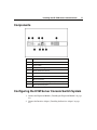
The activity indicator light ("Components" on
page 17) does not display when the HP KVM
Server Console Switch is powered on.
•
Be sure that the HP KVM Server Console Switch is
powered on and that the power source is valid.
•
Be sure that the cables are connected properly.
The system does not recognize the HP IP
Console Switch.
All HP IP Console Switches must be upgraded with
SoftPaq firmware version 2.1.1 or later.
The system does not recognize the Compaq
Server Console Switch.
All Compaq Server Console Switches must be
upgraded with SoftPaq firmware version 2.1.0 or later.
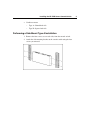
An Expansion Module ("Installing the
Expansion Module" on page 23) is not being
recognize by a Compaq Server Console
Switch.
An Expansion Module ("Installing the Expansion
Module" on page 23) is considered a level of
cascading ("Cascading Console Switches" on page
27) and therefore cannot be used in combination with
a cascaded Compaq Server Console Switch.
The HP KVM Server Console Switch system
is inaccessible after losing the password.
Call the HP Customer Support Center for more
detailed instructions.
The OSD is inaccessible.
Press the Ctrl key twice.
Servers are still listed although they have
been disconnected.
From the Diagnostics dialog box ("Activating Run
Diagnostics" on page 71), click Clear.
HP CONFIDENTIAL
File Name: 339674-1.doc Last Saved On: 8/14/03 3:54 PM