1
Monomachine SFX-6/60 USER’S MANUAL Rev:3 for OS 1.04. This manual is copyright (C) 2004 Elektron ESI AB. All reproduction without
written authorization is strictly prohibited. The information in this manual may change without notice. Elektrons product names, logotypes,
titles, words or phrases may be registered and protected by Swedish and international law. All other brand or product names are trademarks or registered trademarks of their respective holders.
Monomachine SFX-6/60 USER’S MANUAL Table Of Contents
INTRODUCTION1-1
CONVENTIONS IN THIS MANUAL..................................................................................................... 1-1
THE PHILOSOPHY OF THE MONOMACHINE............................................................1-2
KEEP IN MIND..................................................................................................................................... 1-2
HIGHLIGHTS ....................................................................................................................................... 1-2
USER INTERFACE AND CONNECTORS ....................................................................1-4
FRONT / MAIN CONTROL PANEL ..................................................................................................... 1-4
KEYBOARD INTERFACE, SFX-6........................................................................................................ 1-6
REAR CONNECTORS ........................................................................................................................ 1-6
ADDITIONAL REAR CONNECTORS, SFX-6...................................................................................... 1-7
RACK MOUNT KIT (SFX-60 ACCESSORY) ....................................................................................... 1-7
RACK MOUNT KIT ASSEMBLY ..................................................................................................... 1-7
CONNECTING THE UNIT ................................................................................................................... 1-7
CARE INSTRUCTIONS ....................................................................................................................... 1-8
THE LCD USER INTERFACE.......................................................................................1-9
LAYER EDIT AND WINDOWS ............................................................................................................ 1-9
QUICK START ............................................................................................................ 1-11
SELECTING AND PLAYING A PATTERN ......................................................................................... 1-11
PLAYING IN MULTI TRIG MODE ...................................................................................................... 1-12
EXPLORING A PATTERN ................................................................................................................. 1-12
RECORDING A PATTERN USING GRID COMPOSING .................................................................. 1-13
PATTERN LIVE RECORDING ........................................................................................................... 1-13
PARAMETER LOCKS........................................................................................................................ 1-14
MONOMACHINE OVERVIEW ....................................................................................1-15
CHOOSE YOUR WAY OF WORKING............................................................................................... 1-15
SIX INDIVIDUAL TRACKS ........................................................................................................... 1-15
SIX TRACK SEQUENCING.......................................................................................................... 1-15
MIDI SEQUENCING ..................................................................................................................... 1-15
POLY MODE................................................................................................................................. 1-15
MULTI TRIG MODE ...................................................................................................................... 1-15
MULTI MAP MODE....................................................................................................................... 1-15
MONOMACHINE SYNTHESIS ARRANGEMENT ......................................................1-17
MONOMACHINE KITS ...................................................................................................................... 1-18
LOADING A KIT............................................................................................................................ 1-19
LOADING A CLEAR KIT............................................................................................................... 1-19
SAVING AND NAMING A KIT ...................................................................................................... 1-19
UNDO KIT..................................................................................................................................... 1-20
KIT EDITING...................................................................................................................................... 1-20
ASSIGN A MACHINE TO A TRACK............................................................................................. 1-21
SETTING THE MIX BUS .............................................................................................................. 1-22
PARAMETER EDITING ..................................................................................................................... 1-22
TRACK EFFECTS.......................................................................................................1-25
LEVEL................................................................................................................................................ 1-25
AMPLIFICATION PAGE..................................................................................................................... 1-25
AMPLIFIER ENVELOPE .............................................................................................................. 1-25
DISTORTION................................................................................................................................ 1-26
TRACK VOLUME ......................................................................................................................... 1-27
PAN............................................................................................................................................... 1-27
PORTAMENTO............................................................................................................................. 1-27
I of IV
FILTER PAGE .................................................................................................................................... 1-28
BASIC FILTER CONTROLS ......................................................................................................... 1-28
FILTER TRACKING ...................................................................................................................... 1-29
EFFECTS PAGE ................................................................................................................................ 1-30
EQ................................................................................................................................................. 1-30
DELAY .......................................................................................................................................... 1-31
LOW FREQUENCY OSCILLATORS (LFO’s)..............................................................1-33
LFO CONTROLS ............................................................................................................................... 1-33
PAGE AND DESTINATION........................................................................................................... 1-33
TRIG MODE.................................................................................................................................. 1-34
WAVEFORM ................................................................................................................................. 1-35
SPEED.......................................................................................................................................... 1-35
INTERLACE.................................................................................................................................. 1-35
DEPTH.......................................................................................................................................... 1-35
ADDITIONAL KIT SETTINGS .....................................................................................1-37
ASSIGN ............................................................................................................................................. 1-37
JOYSTICK .................................................................................................................................... 1-38
VELOCITY .................................................................................................................................... 1-38
KEY TRACKING ........................................................................................................................... 1-38
TRIG TRACK SETTINGS .................................................................................................................. 1-39
TRIG POS..................................................................................................................................... 1-39
TRIG PORTAMENTO ................................................................................................................... 1-39
LEGATO TRIG MODES ................................................................................................................ 1-39
MULTI TRIG ....................................................................................................................................... 1-40
MULTI TRIG ALL TRACK ............................................................................................................. 1-40
MULTI TRIG SPLIT MODE ........................................................................................................... 1-41
MULTI TRIG SEQUENCER START AND SEQUENCER TRANSPOSE ...................................... 1-41
MULTI ENV ........................................................................................................................................ 1-42
THE PATTERN SEQUENCER ....................................................................................1-43
PATTERN SELECTION ................................................................................................................ 1-43
COMPOSING A PATTERN ................................................................................................................ 1-44
RECORDING PREPARATIONS ................................................................................................... 1-44
GRID COMPOSING...................................................................................................................... 1-44
LIVE RECORDING ....................................................................................................................... 1-46
PARAMETER LOCKS........................................................................................................................ 1-46
PARAMETER LOCKS IN GRID COMPOSING MODE................................................................. 1-47
PARAMETER LOCKS IN LIVE RECORDING MODE .................................................................. 1-48
ADVANCED SEQUENCER CONTROL ............................................................................................. 1-48
TRIG TRACKS.............................................................................................................................. 1-48
TRIGLESS TRIGS ........................................................................................................................ 1-49
PITCHLESS TRIGS ...................................................................................................................... 1-50
SUMMARY.................................................................................................................................... 1-51
THE LINK BETWEEN KITS AND PATTERNS................................................................................... 1-51
SCALE, PAGES AND TIME SIGNATURES....................................................................................... 1-51
SCALE SETUP ............................................................................................................................. 1-51
TEMPO .............................................................................................................................................. 1-52
THE TEMPO SCREEN ................................................................................................................. 1-52
TAP TEMPO ................................................................................................................................. 1-53
EXTERNAL SYNCHRONISATION ............................................................................................... 1-53
PATTERN CHAINING ........................................................................................................................ 1-53
PATTERN COPY CLEAR PASTE ...................................................................................................... 1-54
FULL PATTERN COPY................................................................................................................. 1-54
TRACK COPY............................................................................................................................... 1-55
SUPER COPY .............................................................................................................................. 1-56
NOTE COPY................................................................................................................................. 1-57
PAGE COPY ................................................................................................................................. 1-57
II of IV
ADDITIONAL SEQUENCER FEATURES ...................................................................1-59
THE ARPEGGIATOR......................................................................................................................... 1-59
ARPEGGIATOR BASIC SETTINGS ............................................................................................. 1-59
ARPEGGIATOR MODES IN DEPTH............................................................................................ 1-60
ARPEGGIATOR ENVELOPE TRIGGING SWITCHES................................................................. 1-61
ARPEGGIATO RHYTHM AND OFFSET TRACK ......................................................................... 1-61
TRANSPOSE..................................................................................................................................... 1-62
SWING............................................................................................................................................... 1-63
THE SWING TRACK .................................................................................................................... 1-63
SLIDE ................................................................................................................................................ 1-65
THE MUTE MODE............................................................................................................................. 1-66
MINIMISING THE MUTE WINDOW ............................................................................................. 1-67
POLY MODE...................................................................................................................................... 1-68
THE MIDI SEQUENCER.............................................................................................1-69
USING THE MIDI SEQUENCER.................................................................................................. 1-69
THE MAIN MIDI SEQUENCER INTERFACE ............................................................................... 1-70
COMPARISON WITH THE INTERNAL SEQUENCER................................................................. 1-71
THE SONG SEQUENCER..........................................................................................1-73
SONG FILE OPERATIONS ............................................................................................................... 1-73
LOAD SONG ................................................................................................................................ 1-73
SAVE SONG ................................................................................................................................. 1-74
SONG PLAY ...................................................................................................................................... 1-75
SONG TRANSPORT .................................................................................................................... 1-75
SONG EDITING................................................................................................................................. 1-76
SONG EDIT TRANSPORT ........................................................................................................... 1-77
SONG TRACK TRANSPOSE....................................................................................................... 1-78
SONG EXTRA .............................................................................................................................. 1-78
SONG LOOPS AND JUMPS ........................................................................................................ 1-79
MONOMACHINE ROUTING .......................................................................................1-81
ADDRESSING THE AUDIO OUTPUTS ....................................................................................... 1-81
THE FX MACHINES ..................................................................................................................... 1-81
USING THE AUDIO INPUTS........................................................................................................ 1-82
NEIGHBOUR ROUTING .............................................................................................................. 1-83
MIX BUS ROUTING ..................................................................................................................... 1-84
ROUTING MODE AB=MIX ........................................................................................................... 1-85
ROUTING MODE 6xMONO ......................................................................................................... 1-85
GLOBAL SETTINGS ...................................................................................................1-87
GLOBAL AUDIO SETTINGS ............................................................................................................. 1-87
MASTER TUNE ............................................................................................................................ 1-88
GLOBAL ROUTING...................................................................................................................... 1-88
MONOMACHINE AND MIDI .............................................................................................................. 1-89
MIDI CHANNELS............................................................................................................................... 1-89
INDIVIDUAL TRACK CHANNELS................................................................................................ 1-90
MULTI TRIG CHANNEL ............................................................................................................... 1-90
MULTI MAP CHANNEL ................................................................................................................ 1-90
AUTO TRACK CHANNEL ............................................................................................................ 1-90
ALL CHANNELS........................................................................................................................... 1-90
MIDI CONTROL DATA....................................................................................................................... 1-91
CONTROL OUT1.......................................................................................................................... 1-91
CONTROL OUT2.......................................................................................................................... 1-91
CONTROL IN................................................................................................................................ 1-92
MULTI MAP........................................................................................................................................ 1-93
MULTI MAP EDITOR .................................................................................................................... 1-93
III of IV
SYSEX FILE OPERATIONS1-94
SYSEX SEND ............................................................................................................................... 1-94
SYSEX RECEIVE ......................................................................................................................... 1-95
MIDI SEQUENCER SETTINGS......................................................................................................... 1-97
CREDITS.....................................................................................................................1-99
PRODUCT DESIGN AND DEVELOPMENT...................................................................................... 1-99
INDUSTRIAL DESIGN....................................................................................................................... 1-99
ADDITIONAL DESIGN....................................................................................................................... 1-99
FACTORY DEFAULT SOUND DESIGN ............................................................................................ 1-99
CONTACT INFORMATION .......................................................................................1-100
ELEKTRON SUPPORT ................................................................................................................... 1-100
MONOMACHINE WEBSITE ............................................................................................................ 1-100
ELEKTRON WEBSITE .................................................................................................................... 1-100
POSTAL ADDRESS......................................................................................................................... 1-100
PRODUCT UPDATES...............................................................................................1-101
Appendix A:
MACHINE REFERENCE
SUPERWAVE............................................................................................................... A-1
SUPERWAVE SAW “SWAVE-SAW” ....................................................................................................A-1
SUPERWAVE PULSE “SWAVE-PULSE”.............................................................................................A-2
SUPERWAVE ENSEMBLE ..................................................................................................................A-3
SID ............................................................................................................................... A-4
SID 6581 ..............................................................................................................................................A-4
DIGIPRO ...................................................................................................................... A-5
DIGIPRO WAVE “DPRO-WAVE” .........................................................................................................A-5
DIGIPRO BEAT BOX “DPRO-BBOX” ..................................................................................................A-5
FM+ .............................................................................................................................. A-7
FM+STATIC “FM+STAT” ......................................................................................................................A-7
FM+PARALLELL “FM+PAR” ................................................................................................................A-8
FM+DYNAMIC “FM+DYN” ...................................................................................................................A-8
VO .............................................................................................................................. A-10
VO-6...................................................................................................................................................A-10
FX............................................................................................................................... A-12
THRU .................................................................................................................................................A-12
REVERB ............................................................................................................................................A-12
CHORUS ...........................................................................................................................................A-13
DYNAMIX...........................................................................................................................................A-13
DYNAMIX TUTORIAL...................................................................................................................A-14
Appendix B:
MIDI CONTROL REFERENCE
MONOMACHINE MIDI SPECIFICATION ....................................................................................... 1-1
NOTE ON & NOTE OFF MESSAGES............................................................................................ 1-1
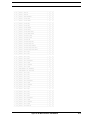
CONTROL CHANGE MESSAGES................................................................................................. 1-2
NRPN MAPPING ............................................................................................................................ 1-5
OTHER MIDI MESSAGES.............................................................................................................. 1-6
IV of IV
Monomachine SFX-6/60
USER’S MANUAL
Copyright 2004 ELEKTRON ESI AB
INTRODUCTION
Thank you for choosing the Monomachine SFX-6/60 as your companion in
music creation. The SFX-6/60 is a powerful and intuitive tool for creating
sounds, melodies and musical compositions of all kinds. We hope you will
have a lot of fun while exploring the vast possibilities of the Monomachine.
To make the most of the SFX-6/60, we would like you to carefully read the
relevant parts of this manual before operating the instrument.
CONVENTIONS IN THIS MANUAL
In this manual we have used certain conventions for indicating input using
knobs and buttons through the user interface. These conventions are listed
below.
Keys (buttons) are written in upper case with bold style, and they are
enclosed in brackets. For instance, the key “function” on the main panel is
written [FUNCTION].
Encoders (knobs) are written in upper case with bold, italic style. For
instance, the encoder “level” is written LEVEL.
LED indicators like the record LED are written <RECORD>.
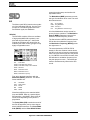
The following symbols are used throughout the manual:
This symbol indicates information that you need to pay attention to.
This symbol indicates a tip that might make it easier interacting with
the SFX-6/60.
1
THE PHILOSOPHY OF THE MONOMACHINE
THE PHILOSOPHY OF THE MONOMACHINE
Synthesizers are available in many different types and forms. Nevertheless,
for most part they follow the norm how a synthesizer of its era is expected to
be. Development for musicians tools generally comes in form of new synthesis techniques or increase in polyphony, memory or other quantitative
elements. The advances in the music machine world have brought numerous good inventions for musicians. However, we believe the core of usability
is easily lost in the hunt for the highest specifications.
With the Monomachine we have tried creating a synthesizer free from prejudice, and focus on what actually spur creativity and not let the technology
stand in your way. We want to inspire you to make sounds and music you
didn't even think of when you first sat down.
We have put all our efforts into explore, to the fullest extent, the concept we
believe is one of the most creative in the history of synthesizers - the monophonic synthesizer with a tightly integrated sequencer. The Monomachine
offers ground breaking sound synthesis machines, divided into five Monosynths, together with dedicated Track Effect engines. The sound synthesis
tracks are controlled through the worlds most advanced pattern based
sequencer, inspired from the concepts of grid programmed drum machines.
KEEP IN MIND
The Monomachine is a very multifaceted synthesizer. Depending on how
you choose to use it certain aspects of it will be most important to you. We
have combined what we have enjoyed most of the traditions of synthesizers
with many new creative approaches.
Try to find your own way of working, whether it being using the song
sequencer to build complete songs, building patterns for real-time manipulation using the Multi Trig function, or using your favourite sound in poly mode.
This users manual will guide you through all the functions, and give some
hints on applications, but you will probably appreciate the full capabilities
after some time of use.
HIGHLIGHTS
• 6 Track Internal Sequencer with sound synthesis
• 6 Track External MIDI Sequencer
• 5x Monosynths: SuperWave, SID, DigiPRO, FM+, VO
• 6x Tape-style Tempo synced delays
• 18x Tempo synced LFO's
• Full real-time control
• Man-Machine potential
2
Monomachine SFX-6/60 USER’S MANUAL
THE PHILOSOPHY OF THE MONOMACHINE
Monomachine SFX-6/60 USER’S MANUAL
3
USER INTERFACE AND CONNECTORS
USER INTERFACE AND CONNECTORS
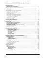
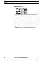
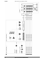
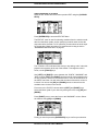
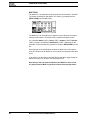
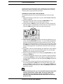
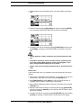
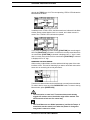
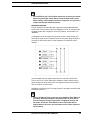
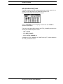
FRONT / MAIN CONTROL PANEL
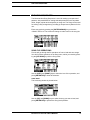
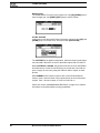
The Monomachine SFX-6 main control panel / SFX-60 front panel:
1.
Master volume control. Sets the volume for the main output and headphone jack.
2.
The LCD graphical interface display.
3.
LEVEL encoder. Sets the overall volume level of the track in focus.
4.
DATA ENTRY encoders. Used for tweaking parameters for the
machines and effects.
• The DATA ENTRY and LEVEL encoders allow accelerated editing by
pressing the knob while turning it.
4
5.
[DATA PAGE] selection keys. These keys are used for selecting the
focus of the DATA ENTRY encoders. The current selection is indicated
by the <DATA PAGE> LED’s to the left of these keys. Press both [DATA
PAGE] keys simultaneously to open the Multi Env window.
6.
[TRACK] keys 1-6. These keys are used for selecting which track is in
focus of editing. The secondary function is to [MUTE] or activate the
track. The <TRACK> LED’s are located to the left of the [TRACK] keys.
These indicate which tracks are active or muted, and also which track is
in the editing focus. The LED colours indicate as follows: Green =
Active, Non-lit = Muted, Red = Active in focus, Yellow = Muted in focus
7.
[TEMPO] key. Press to bring up the tempo window for adjustment. The
current tempo is always indicated by the speed the <TEMPO> LED is
flashing. Holding function you can use [TEMPO] for tapping the tempo.
Monomachine SFX-6/60 USER’S MANUAL
USER INTERFACE AND CONNECTORS
8.
[FUNCTION] key. Press and hold it for accessing the secondary function of another key.
9.
[KIT/SONG] key. Calls the kit or the song menu, depending which
mode is chosen. The secondary function is calling the [GLOBAL]
menu.
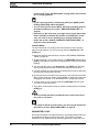
10. [TRIG] keys 1 to 16. Main functions of these keys are as keyboard for
trigging notes, and for editing notes in grid edit mode. Also used for
choosing pattern, if pressed while holding [BANK] keys. When functioning as musical keyboard, the notes are played with velocity 80. Hold
[FUNCTION] while playing to play with full velocity (127).
11. [PATTERN/SONG] key. Switches between pattern and song sequencer
mode. The current sequencer mode is indicated by the <PATTERN>
and <SONG> LED’s. The secondary function is to set the unit in
[POLY] mode.
12. [ENTER/YES] and [EXIT/NO] keys. Used for entering and exiting
menus and for confirming choices or aborting functions.
13. The [CURSOR] keys. Used for menu navigation. The [CURSOR] keys
are individually named [UP], [DOWN], [LEFT] and [RIGHT].
When in base pattern edit mode, [UP] and [DOWN] are used for setting
the octave for the [TRIG] keys.
14. [BANK GROUP] key. Used for switching between bank group A to D
and E to H. The <BANK GROUP> LED’s to the right indicate the current
selection. The secondary function is to enter the dedicated [MUTE
MODE].
15. [A/E], [B/F], [C/G] and [D/H] [BANK] keys. Hold one of the [BANK]
keys and then press one of the [TRIG] keys to select the pattern (A01H16) indicated by the label of the [BANK] key and the <BANK
GROUP> LED’s. The secondary functions are to edit the track settings
for [ARPEGGIATO], [TRANSPOSE], [SWING] and [SLIDE].
16. [REC], [PLAY], [STOP] keys. The [REC] key is used for toggling grid
edit mode on/off. [PLAY] Initiates playback of a pattern or song. Pressing [PLAY] a second time pauses playback. Press [PLAY] while holding
[REC] to enter live recording mode. [STOP] halts the playback of a pattern or song. Press [STOP] twice to rewind the song and turn off all
sound and reset various things. In grid edit mode, the <RECORD> LED
gives a steady light, while in live recording it flashes. The secondary
functions of the keys are [COPY], [CLEAR] and [PASTE].
17. [SCALE] key. In grid recording mode: switches the trig page focus of
the [TRIG] keys if the scale length exceed 16. The trig positions are
organised in up to four pages with 16 positions in each. The <TRIG
PAGE> above the [SCALE] key indicate which page is currently being
edited or played. The secondary function is calling the [SCALE
SETUP] menu.
18. [TRIG SELECT] key. Switches which trig track is programmed from the
[TRIG] keys. The <TRIG TRACK> LED’s to the left indicate the current
Trig Track selection. The secondary function is to enter or exit the [MIDI
SEQ] mode.
Monomachine SFX-6/60 USER’S MANUAL
5
USER INTERFACE AND CONNECTORS
KEYBOARD INTERFACE, SFX-6
1. Joystick, for real-time expression control. The joystick can individually
control parameters for all tracks.
2. Keyboard, for real-time playing, real-time recording and grid recording.
3. [MULTI TRIG] key, used for toggling the Multi Trig mode. The current
state of the Multi Trig is indicated by the <MULTI TRIG> LED above. The
secondary function is to toggle the [MULTI MAP] mode. Multi Map is indicated by the <MULTI TRIG> LED flashing.
4. [OCTAVE] keys. Control which octaves the Keyboard is playing, and
which notes are represented on the <KEYBOARD> LED’s.
5. <KEYBOARD> LED’s. Shows the notes being played on the active track,
or programmed on a step selected in Grid edit mode.
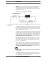
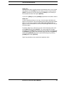
REAR CONNECTORS
1. Power On/Off switch (SFX-60 only).
2. AC 6 Volt power in (SFX-60 only).
• Caution! Use only an Elektron-approved power supply with your
Monomachine SFX-60. Tip specifications: 5.5mm outer diameter,
2.5mm inner diameter, Electrical specifications: 6 Volts AC at
2000mA, 50/60Hz. Using the wrong type of adapter may result in
damage to your unit. Damage caused by the use of incorrect power
supply is not covered by warranty.
3. MIDI Thru/Out/In
4. Audio Input B/A
5. Individual Audio Outputs F/E/D/C
6. Main/Individual Audio Outputs B/A
7. Stereo Headphone Outputs (Amplified copy of output AB)
6
Monomachine SFX-6/60 USER’S MANUAL
USER INTERFACE AND CONNECTORS
ADDITIONAL REAR CONNECTORS, SFX-6
1. AC 115/230V 50/60Hz Input with integrated fuse holder and spare fuse
storage.
• Caution! Although the Monomachine SFX-6 can accept both 115 and
230 Volts main current, both the voltage selector and the fuse need
to be matched to the voltage. The fuse holder has two sections. The
inner is the one currently in use.
For 115V operation the fuse should be specified as 250mA, 125V.
For 230V operation the fuse should be specified as 125mA, 250V.
2. Power On/Off switch.
3. Voltage selector.
• Caution! If you want to change the voltage for the Monomachine,
please take notice of the warning of first point of this section.
RACK MOUNT KIT (SFX-60 ACCESSORY)
The Monomachine SFX-60 can be rack mounted in a standard 19” rack,
using the SFX-60/SPS-1 rack mount kit which is ordered separately. When
rack mounted, the SFX-60 occupies four standard height units plus additional space needed to accommodate cables plugged into the unit at the
back.
RACK MOUNT KIT ASSEMBLY
Make sure that you use screwdriver of the right size, and is in good condition. Use the included “M3” sized screws to secure the rack mount consoles
on each side of the SFX-60. Make sure that all screws are fastened for
secure operation of the unit.
CONNECTING THE UNIT
Follow the basic guide below to power up your unit first time.
1. For SFX-6: Insert the supplied power cord in a grounded wall socket,
specified as the voltage selector on the back of your SFX-6.
For SFX-60: Insert the supplied AC adapter into the wall socket, and connect the small plug into the rear of the unit.
2. Connect the Main Audio Out A/B from the Monomachine to your mixer or
amplifier, and/or connect a pair of stereo headphones to the Headphone
Output.
3. If MIDI control is desired, connect the MIDI OUT from the Monomachine
to the MIDI IN of the device you wish to send data to. Connect the MIDI
IN of the Monomachine to the MIDI OUT of device that you wish to
receive data from. The MIDI THRU port is “echoing” the data coming in
Monomachine SFX-6/60 USER’S MANUAL
7
USER INTERFACE AND CONNECTORS
from the MIDI IN port, so it can be used for daisy chaining other MIDI
units.
4. Switch all units on.
5. If you do not have any previous experience of the Monomachine we sug-
gest that you follow the “QUICK START” on page 11.
CARE INSTRUCTIONS
To ensure many years of trouble free operation, please follow the advice
below:
• Never use any aggressive cleaners on the casing or the LCD overlay. Remove dust, dirt and fingerprints with a soft dry cloth. More
persistent dirt can be removed with a slightly damp cloth using only
water.
• Never use sharp objects near the display to avoid scratches or damage. Also avoid applying any pressure to the display itself.
• When transporting the Monomachine, try to use the box in which it
was originally shipped with the padding supplied, or equivalent
packaging. For the SFX-60 we can recommend using the specially
designed transportation bag for sale at the Elektron webpage.
• Make sure that you place the unit on a stable surface before use. If
you mount the unit in a rack, be sure to tighten all four screws in the
rack mount holes.
• The memory used for storing patches and kits is powered by a battery inside the unit. It will hold data at least 6 years before needing
replacement. If the battery needs replacement, the “battery low”
message will appear in the display. Contact Elektron support or your
nearest repair center.
8
Monomachine SFX-6/60 USER’S MANUAL
THE LCD USER INTERFACE
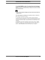
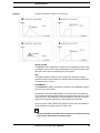
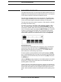
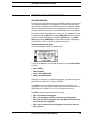
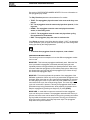
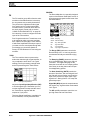
THE LCD USER INTERFACE
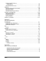
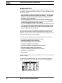
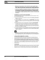
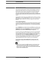
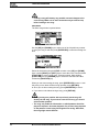
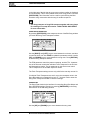
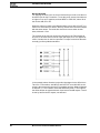
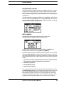
The center of the Monomachine SFX-6/60 editing is the LCD graphical interface display. The main interface screen for base pattern edit mode is printed
below:
1. The current tempo. This will show EXT when synced to external tempo.
2. Level bar showing the overall volume level of the machine on the track in
focus.
3. Up to eight Data Entry parameters. At the top are up to four characters
which is an abbreviation that indicate their current function. Below the
function name is a symbol that display the current value of the parameter.
This value will also be displayed in figures as the parameter is altered or
the encoder is pressed.
4. Four rectangular boxes showing the playback position in the pattern.
5. The playback/recording status shown by the standard “rec”, “play” and
“stop” symbols.
6. Name and number of the current kit.
7. The index of the current pattern, ranging from A01 to H16.
8. Specification of the Mono-synth and machine of the track in focus.
LAYER EDIT AND WINDOWS
When a function puts a window on top of the base control window, it will
change the function of certain keys and/or encoders. The keys that are not
used or blocked can still be used to control the layer underneath. For example, when you have called the tempo function it will make use of the LEVEL
encoder, but you can still use the DATA ENTRY knobs to control the Data
Entry parameters of the track in focus.
All windows can be closed using the [EXIT/NO] key.
Monomachine SFX-6/60 USER’S MANUAL
9
THE LCD USER INTERFACE
10
Monomachine SFX-6/60 USER’S MANUAL
QUICK START
QUICK START
This quick start will guide you through some of the basic operations get you
started using the Monomachine. First connect your unit as described in section “CONNECTING THE UNIT” on page 7.
• The DATA ENTRY encoders have accelerated editing when pressed.
By default, the knobs increase/decrease the parameter value in
steps of +1/-1. When pressed, the step length is higher, allowing
quicker adjustments.
This guide assumes you have a Monomachine SFX-6 Keyboard or SFX-60
Tabletop with a midi keyboard connected. If you have a SFX-60 you need to
take care to set the midi keyboard to play on the correct midi channel. When
we refer to play a sound in Multi Trig mode, a MIDI keyboard should be
sending on the Multi Trig channel. By default this is set to MIDI channel 7.
When playing on a specific track we recommend using the Auto Track channel which will switch focus depending on which track is selected with the
[TRACK] keys. By default the Auto Channel is assigned to midi channel 9.
Please refer to section “MIDI CHANNELS” on page 89 for more information
on the MIDI channel assignment of the Monomachine.
SELECTING AND PLAYING A PATTERN
1. Verify that the <PATTERN> LED is lit and the <SONG LED> is not. If this
isn’t the case, press the [PATTERN/SONG] key.
2. Check the <BANK GROUP> LED to see if bank group A-D or E-H is
active. If needed press [BANK GROUP] key to toggle the active bank
group. For this demonstration use group A-D.
3. To select pattern A01, press and hold the pattern selection key [A/E] and
then press the [TRIG] key 1. You can see the index of the currently
selected pattern in the lower left corner of the display. Each pattern automatically loads the kit it was created with. The name of the kit is also
shown in the display.
4. To listen to the pattern, press the [PLAY] key. The pattern starts playing
and loops back to the beginning again when it has reached its end.
Pressing [PLAY] while playing pauses the playback.
5. To change pattern during playback, simply select a pattern the same way
as in step 3. The display will show the selected pattern beside the current
one, but with an arrow pointing between them. This indicates that once
the current pattern has played to its end, the new selected pattern will
start playing.
Monomachine SFX-6/60 USER’S MANUAL
11
QUICK START
6. To stop the playback of the pattern, press the [STOP] key.
PLAYING IN MULTI TRIG MODE
1. Select a pattern, ranging from A01-D16. All the Monomachine presets are
located in this range. Make sure the sequencer is stopped.
2. Enter Multi Trig Mode. On SFX-6 press the [MULTI TRIG] key and check
that the <MULTI TRIG> LED is lit with a steady light. For SFX-60 select
the Multi Trig channel on your midi keyboard.
3. Play some notes!
4. Depending on the trig mode selected in the kit a number of things could
happen. Please refer to section “MULTI TRIG” on page 40 for a the full
story.
• All presets of the Monomachine are designed as patterns with associated kits that can be played in Multi Trig mode. To explore the presets, select the patterns between A01 and D16, and play them in
Multi Trig mode as described in this section.
EXPLORING A PATTERN
1. Select a pattern as described above.
2. Make sure the sequencer is stopped and that Multi Trig Mode is switched
off on the SFX-6 (<MULTI TRIG> LED not lit) and that the sequencer is
not in grid composing mode (<REC> LED not lit). Use the Auto Channel if
using an external MIDI control keyboard.
3. Select one of the six tracks as the active track by pressing a [TRACK]
key.
4. For each track the machine loaded is displayed in the lower left corner of
the display.
5. Play some notes on each of the tracks, either using the keyboard or the
[TRIG] keys. Note that it’s possible that not all tracks will sound, the track
can be an FX that needs input from another track or silenced due to the
output assigning, machine selection or Track Effect settings.
6. Use the [DATA PAGE] keys to navigate between the Data Pages. The
<DATA PAGE> LED’s will indicate the current selection. Select the Synthesis page.
7. Now, turn any of the DATA ENTRY knobs to tweak the machine synthesis
parameters on the selected track. You can change any parameters without fear of loosing presets or other kits stored, as the changes will not be
saved if you do not choose to perform the Kit Save action. The parameters presented on the Synthesis page are specific to the machine loaded.
See Appendix: A for information about the parameters and functions of
the machines.
8. Continue to the Track Effect pages, named Amplification, Filter and
Effects pages and explore the wide range of sound shaping tools available. The parameters on these pages are always placed in the same order
to assist the sound creation process. You can find information about the
Track Effects on page 25.
12
Monomachine SFX-6/60 USER’S MANUAL
QUICK START
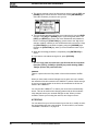
RECORDING A PATTERN USING GRID COMPOSING
1. You can input notes into a pattern of the sequencer, both while it is play
and stop mode. First select the pattern you wish to edit. You might want to
select an empty pattern, as all changes are made “live” to the pattern. As
factory default, patterns E01-H16 are clear.
2. If you wish you can change the kit assigned to the pattern by selecting
pressing the [KIT] key, then select LOAD in the menu, and select the kit
you prefer from the list presented.
3. Press the [RECORD] key to enter grid recording mode. The <RECORD>
LED should be firmly lit.
4. Select the active track using the [TRACK] keys.
5. Press a [TRIG] key to add a Note On trig. A Note On trig is indicated by a
red <TRIG> LED. To set the pitch of the note, press the corresponding
key on the keyboard while the [TRIG] button is held. You can also use the
[CURSOR] keys to edit the programmed pitch. Pressing the same [TRIG]
key once more removes the Note On.
6. To enter a Note Off trig, press a [TRIG] key while holding the [FUNC-
TION] key. To remove a Note Off the same [TRIG] key must be pressed
twice. A Note Off is indicated by a yellow <TRIG> LED.
7. To change the pitch of a note, press and hold the [TRIG] key. You will see
a mini keyboard pop up in the lower left corner of the screen. Either press
the new note on the keyboard or use the [CURSOR] keys to select the
new note. When done release the [TRIG] key.
8. To edit other tracks, change the active track using the [TRACK] keys.
PATTERN LIVE RECORDING
1. The live recording mode allows you to record notes in real-time while the
pattern is playing. To start this mode, press and hold [RECORD] and then
[PLAY].
2. You can now play notes on the track you want to record. All played notes
will be quantised and recorded to the closest trig step.
3. If a note is played on a position where there already was a note pro-
grammed the new note will replace the note on that step.
4. To erase notes on live recording mode hold [EXIT/NO] while the notes
you want to remove are heard.
5. The pattern will loop and be ready for further recording until you press the
[STOP] key.
Monomachine SFX-6/60 USER’S MANUAL
13
QUICK START
PARAMETER LOCKS
1. To lock parameters to a specific trig in the pattern in grid composing
mode, then hold a [TRIG] key and turn or click an encoder. The parameter connected to the encoder will be inverted to indicate that it now is has
a parameter lock. The corresponding <TRIG> LED will flash rapidly to
indicate that a parameter is locked for that step.
2. In live recording mode, you can lock parameters by turning a knob while
recording.
3. Parameters can be locked for any parameter and track. To lock parame-
ters for a new track, select that track with the [TRACK] button and repeat
the steps above.
4. To remove a single lock in grid edit mode, press and hold the [TRIG] key
and click the encoder connected to the parameter you wish to remove.
You will see that the inverted square around the parameter is removed.
To remove all parameter locks for a trig, hold the [TRIG] key and press
[CLEAR]. The locks are also cleared when the note is removed.
14
Monomachine SFX-6/60 USER’S MANUAL
MONOMACHINE OVERVIEW
MONOMACHINE OVERVIEW
The sound generating structure of the Monomachine differs in many ways
from what is common for contemporary sound synthesizers and sequencers. The SFX-6/60 offers six tracks of audio synthesis/FX, effects and
sequencing. All six tracks are fully equipped with a sound generating or
sound effecting machine of choice, Track Effect engine including amplifier
envelope, LP/BP/HP filter, synchronised tape-style delay, three LFO’s and
the most refined step sequencer. Please refer to figure “Monomachine
sound synthesis overview” on page 16 for an overview of the general structure of the Monomachine.
CHOOSE YOUR WAY OF WORKING
The Monomachine offers you many ways of working. The six tracks of synthesis can be approached in several ways. Some suggestions how you
could organise your work is described below. All the techniques presented
will be discussed in detail later in this manual.
SIX INDIVIDUAL TRACKS
Each of the six tracks can be programmed with individual sound generating
machines and sound and effects settings. All tracks can be controlled by
their dedicated MIDI channel if preferred. Using the Monomachine this way
offers you access to six independent tracks of monophonic synthesis.
SIX TRACK SEQUENCING
The six tracks can be controlled by the Monomachine sequencer. In addition
to the traditional pitch and note on/off commands, it allows direct control
over all sound generating parameters and envelope trigs.
MIDI SEQUENCING
Six additional tracks of polyphonic MIDI sequencing for controlling external
gear are lined up beside the sequencer for the internal sound generating
tracks.
POLY MODE
By entering Poly mode the Monomachine dedicates all six sound generating tracks to offer one track of six-voice polyphonic sound.
MULTI TRIG MODE
In Multi Trig mode, all six sound generating tracks are controlled from one
single control track. The sequencer can be a part of the control, and your
sequencers can be transposed in real-time. This way you can construct the
most dynamic and complex monophonic super-sounds imaginable. The presets of the Monomachine are designed to be used in this mode.
MULTI MAP MODE
Using the Multi Map mode you can lay out your sequences over a keyboard,
for live or studio use.
Monomachine SFX-6/60 USER’S MANUAL
15
FIGURE 1.
Monomachine sound synthesis overview
16
Monomachine SFX-6/60 USER’S MANUAL
MONOMACHINE SYNTHESIS ARRANGEMENT
MONOMACHINE SYNTHESIS ARRANGEMENT
The basic sound generating unit in the Monomachine is a machine. Each
machine is designed for generating sounds from a specific technique or
method, such as analogue style pulse, SID MOS6581 or dynamic FM. The
sound generating machines allows you to get many different starting points
with varied sound characteristics.
The machines are grouped in so called Mono-synths. It can be viewed as if
the machines in a Mono-synth belong to the same family. For example, in
the FM+ family there are a total of 3 machines for static, parallel and
dynamic FM synthesis. Despite the fact that each machine is based on the
family synthesis, each machine can have a unique parameter set. The
parameters are selected individually to give the user the best control of the
machines. There is a special Mono-synth named FX. The machines in this
family do not generate sounds, but offers effects for other tracks.
Description of Mono-synths and their parameters are covered in
Appendix: A.
Each of the six tracks can have any machine assigned to it. The assignment
of machines and their parameter settings are collected in kits. Editing the
kits is discussed in section “KIT EDITING” on page 20.
All six tracks have their dedicated effect modules. The effect modules are
named Track Effect Systems. The amplifier envelope generator is detached
from the synthesis, and can be found as part of the Track Effect System.
Each Track Effect delivers hi/lo/band-pass resonant 24-db filter with envelope and individual Q-control, 1-band eq, sample rate reduction, distortion
and tempo synchronised tape-style delay. You will also find controls for left/
right-pan and portamento speed among the Track Effects Data Entry pages.
The Track Effect System is explained in section “TRACK EFFECTS” on
page 25.
Each track offers three powerful Low Frequency Oscillators (LFO’s). The
three LFO’s offer identical functionality, and can be assigned to any
machine, Track Effect or LFO parameter. You will find more information
about the LFO’s on page 33.
Monomachine SFX-6/60 USER’S MANUAL
17
MONOMACHINE SYNTHESIS ARRANGEMENT
MONOMACHINE KITS
The Monomachine do not arrange sounds in what is commonly referred to
as “patches”. The Monomachine equivalence of a “patch” depends on which
way you are using it.
• If you use the six tracks as individual synthesizers, or in poly mode,
then you could see the kit as carrying six “patches”. The kit would
then be the equivalence to what in common synthesizer terms is
referred to as a “performance”.
• If you use the Multi Trig mode, then all six tracks would be trigged
from the Multi Trig track. A kit would then be the direct equivalence
of what is commonly referred to as a “patch”.
• If you use the Multi Trig mode and incorporates the sequencer, then
your “patch” would incorporate both the kit and the sequencer pattern from which it is linked. This is how and the presets that come
with your Monomachine are set up.
If you are used to the structure of ordinary synthesisers, the Monomachine
way of structuring sounds in patterns and kit might be confusing at first.
Hopefully, after some time of use you will appreciate the flexibility and ease
of use of the Monomachine implementation.
As a reference, Monomachine kits hold the information specified below:
•
•
•
•
•
•
•
•
•
The machines selected for each of the 6 tracks
Parameter settings for the 6 machines
Parameter settings for the 6 Track Effects
Parameter settings for the 6x3 LFO’s
Parameter settings for the 6 MIDI sequencer tracks
Input and output routings for the 6 tracks.
Trig track and Multi Trig settings for the 6 tracks.
Parameters for the Multi-env.
The Kit name
All kits are battery backed and user definable. A total of 128 user kits can be
stored in memory.
You access all the parameters that are stored in kits from the Data Entry
pages, and in the KIT menu. Open the main kit menu with the [KIT] key.
18
Monomachine SFX-6/60 USER’S MANUAL
MONOMACHINE SYNTHESIS ARRANGEMENT
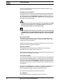
LOADING A KIT
1. Open the KIT window.
2. Use the arrow keys to move to the “LOAD” icon. Press [ENTER/YES] to
call the LOAD KIT menu.
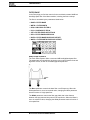
3. The screen presents a list of the kits stored in memory. Use the [UP] and
[DOWN] keys to choose among the 128 kit slots. Press [ENTER/YES] to
load the kit of your choice.
If you want to exit without loading a kit, press [EXIT/NO].
• The kit currently loaded is indicated by an inverted selection box.
The focus, when moved away from the kit currently loaded, is a hollow square box.
LOADING A CLEAR KIT
To get a clean kit, open the KIT LOAD window as described above and load
a position where no kit was previously saved. The clear positions are indicated with “--” as the kit in the square box focus below.
After loading a clear kit, you will get six tracks loaded with the GND>SIN
machine, and all Track Effects and other parameters reset to default values.
SAVING AND NAMING A KIT
1. Open the kit window.
2. Use the arrow keys to move to the “SAVE” icon. Press [ENTER/YES] to
open the KIT SAVE menu.
Monomachine SFX-6/60 USER’S MANUAL
19
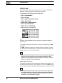
MONOMACHINE SYNTHESIS ARRANGEMENT
3. The screen presents a list of the kits stored in memory. Use the [UP] and
[DOWN] keys to choose from the 128 kit slots. Press [ENTER/YES] to
select the slot where you want to save your kit.
4. The next window appearing will allow you to name the kit. Use the LEVEL
encoder or the [UP] and [DOWN] keys to cycle through the letters. The
[LEFT] and [RIGHT] keys move the cursor backwards and forwards on
the line. Pressing the [FUNCTION] key gives access to the “high score”
selection method, in which you see all characters at the same time. Keep
the [FUNCTION] key held while navigating using the [CURSOR] keys.
Release the [FUNCTION] key, when you have located the letter of your
choice.
5. When the kit naming procedure is completed, press [ENTER/YES] to
save it.
6. If you want to exit without saving the kit, press [EXIT/NO].
• You can copy paste and clear kits in the Kit load and save windows.
Press the [COPY], [CLEAR] or [PASTE] keys while holding [FUNCTION] to perform the preferred action.
UNDO KIT
There is a special kit in the first position of the kit list named the “UNDO
KIT”.
When you have made unsaved changes to a kit and a new one is loaded,
the unsaved old kit will be stored in the “UNDO KIT” position. When saving a
kit over an occupied position in the kit list, the overwritten kit will also be
saved in the “UNDO KIT”.
You can load the “UNDO KIT” to restore your most recent unintentionally
lost kit. This can be useful when changing pattern and the kit is automatically changed so that your unsaved changes are lost. When you have
needed to restore your kit using the undo kit, don’t forget to save it.
KIT EDITING
You can either form your kit from scratch from a clear kit, or modify an existing one and then save it to a new position. To load a clear kit, see section
“LOADING A CLEAR KIT” on page 19.
20
Monomachine SFX-6/60 USER’S MANUAL
MONOMACHINE SYNTHESIS ARRANGEMENT
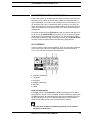
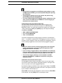
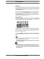
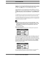
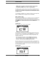
ASSIGN A MACHINE TO A TRACK
Open the KIT window and select menu position EDIT using the [CURSOR
KEYS].
Press [ENTER/YES] to enter the EDIT KIT Menu.
The EDIT KIT menu is used for selecting machines from the selection available from the Mono-synths, and for specifying to which audio mix bus the
output should be directed. For FX machines you also select the audio input
for the machine. Read more about FX machines and routing in section
“MONOMACHINE ROUTING” on page 81.
The <TRACK> LED’s indicate which track you are editing, and it is also displayed in the name bar at the top of the window. To change the track in
focus, use the [TRACK] keys.
Use [LEFT] and [RIGHT] to move between the “SYNTH”, “MACHINE” and
“MIX” columns. [LEFT] and [RIGHT] are also used for moving between the
out bus positions, and for FX machines as well to move to the selections in
the INPUT row below. You will notice that the name of the active column is
inverted. You can use the [UP] and [DOWN] arrows to choose from the
available menu choices in the column.
First move to the “SYNTH” column with the [LEFT] and [RIGHT] keys.
Select the Mono-synth of your choice by moving the focus using [UP] and
[DOWN].
Press [RIGHT] once to move the focus to the “MACHINE” column. Select
the machine using [UP] and [DOWN].
Finally you need to press the [ENTER/YES] key to confirm your selection.
Monomachine SFX-6/60 USER’S MANUAL
21
MONOMACHINE SYNTHESIS ARRANGEMENT
• The Mono-synth and the machine currently assigned to the track are
indicated by inverted selection boxes. The focus, when moved away
from the machine currently loaded, is a hollow square box. When
[ENTER/YES] is pressed, the current focus will be assigned, thus
changing the square hollow focus to the inverted box.
• From inside the Edit Kit window you can copy clear and paste the
machine selection, together with all parameter settings of the Data
Entry pages using the [COPY], [CLEAR] and [PASTE] keys while
holding [FUNCTION]. See section “SUPER COPY” on page 56 for
more information.
SETTING THE MIX BUS
The Mix bus settings can be used for directing to which audio outputs the
audio of the machine should go. It can also be used for advanced routing
using FX machine effects.
When FX machines are not used for any tracks, and the master routing is
not changed from the default “3xSTEREO”, the OUT BUS selection in the
MIX column only select to which pair(s) of stereo outputs the audio output of
the machine will be directed.
For more information on FX machines and how the Mix bus routing can benefit them, please check section “MONOMACHINE ROUTING” on page 81.
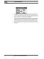
PARAMETER EDITING
Each Monomachine track offers 56 parameters for the sound generation
and effects. They are divided into seven pages with eight parameters in
each.
The sound generating machines forms their sound from one page of up to
eight parameters, named the Synthesis parameters. The Track Effects are
composed from 24 parameters, divided into three pages of Amplification,
Filter and Effects. There are also three pages for the LFO’s, these brings 24
parameters in total.
First, exit all windows using [EXIT/NO], and see to that you are in the base
pattern edit mode (see section “RECORDING PREPARATIONS” on
page 44). You should see the base window displayed below. The visual
parameter names and symbols will depend on the machine assigned.
Use the [DATA PAGE] keys to control the focus of the DATA ENTRY encoders. The <DATA PAGE> LED’s will indicate the current focus and the visual
parameters will be updated depending on the focus.
22
Monomachine SFX-6/60 USER’S MANUAL
MONOMACHINE SYNTHESIS ARRANGEMENT
Turn the DATA ENTRY encoders. The corresponding visual parameter on
the LCD screen should be updated accordingly. Press and turn the DATA
ENTRY encoders for accelerated editing. Just press it to see the numerical
value of the parameter.
• If you want to keep the changes you have done to the kit, don’t forget to save it!
The TUNE parameter is available for all synthesis machine. It allows fine
pitch tuning of 100 cents up or down.
For information about the various Mono-synths, and their respective
machines, please see Appendix: A. Here you will find background information about all the Mono-synths, and specifications of the parameters of all
machines.
For information about the Track Effects, please refer to section “TRACK
EFFECTS” on page 25. For information about the LFO’s, please refer to
section “LOW FREQUENCY OSCILLATORS (LFO’s)” on page 33.
Monomachine SFX-6/60 USER’S MANUAL
23
MONOMACHINE SYNTHESIS ARRANGEMENT
24
Monomachine SFX-6/60 USER’S MANUAL
TRACK EFFECTS
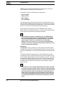
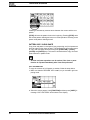
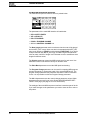
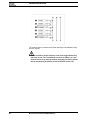
TRACK EFFECTS
The Track Effects are independent effects systems, available to the six
tracks as extensions to the machine synthesis. This chapter is a reference
to all the functions you will find on the Data Entry pages.
The Track Effects are applied to the sound signal in stereo in the order as
described in the figure below:
First select a track using the [TRACK] keys that you want to alter the Track
Effects for. If you want to hear the effect of the EQ or the Filter, it is wise to
choose a machine that generates full harmonic contents, such as the
SWAVE-SAW. The GND-SIN only contains power in one single frequency,
and will not provide a good base for understanding of the EQ and Filter.
Then use the [DATA PAGE] keys to locate the relevant Data Entry page.
The <DATA ENTRY> LED’s indicates which Data Entry page is currently
selected, and the DATA ENTRY encoders now control the parameters of the
Data Entry page selected.
LEVEL
The Level (“LEV”) parameter is available from all Data Entry pages. You can
always reach it with the dedicated LEVEL encoder.
Level controls the overall audio level of the track. It is applied at the end of
the audio signal path of the track. The Level is designed as a master level
control that can not be locked or assigned as a destination from the LFO’s or
Assign. If you want to do this, use the Track Volume parameter on the
Amplification page. See section “TRACK VOLUME” on page 27 for more
information on this parameter.
AMPLIFICATION PAGE
In the Amplification page you find the controls for the amplifier envelope
(AHDR), Distortion, Volume, Pan and Portamento.
AMPLIFIER ENVELOPE
The amplifier envelope is trigged every time an AMP-trig is received. This
normally happens when a key has been pressed on the Keyboard or the
[TRIG] keys, or played from the sequencer or received over MIDI. The
Monomachine SFX-6/60 USER’S MANUAL
25
TRACK EFFECTS
AMP-trig can be controlled individually from the sequencer, see section
“TRIG TRACKS” on page 48 for more information.
The amplifier envelope is controlled by the parameters:
•
•
•
•
ATK = ATTACK
HOLD = HOLD
DEC = DECAY
REL = RELEASE
The Attack parameter controls how long time the envelope takes to reach
full level, after the AMP-trig has been received. The full level is then held for
the amount of time specified by the Hold parameter. The level then declines
down to zero, by the time specified by the Decay parameter.
If the key played is released at any time (in MIDI this event is named
NOTE_OFF), the release phase take over. The level will then decline down
to zero by the time specified by the Release parameter.
• The traditional envelope for synthesizers is in the ADSR (Attack,
Decay, Sustain, Release) form. For the Monomachine the Sustain
has been exchanged for Hold. The Hold parameter is very handy
when using the sequencer, as it allows you to skip setting
NOTE_OFF events in normal use. If you want to simulate ADSR
behaviour you can use the ramp and exp shapes of the LFO’s, with
the VOL as destination parameter.
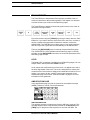
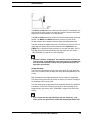
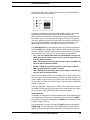
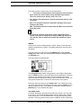
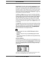
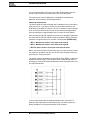
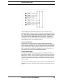
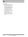
DISTORTION
The Distortion (“DIST”) parameter controls the signal overload distortion.
The distortion is applied as an integrated part of the filter, and controls part
of the filter characteristics. It also controls the headroom for the filter and the
EQ.
Increasing the distortion parameter from 0 and 64 strengthen the signal
overload for the track. If the EQ or filter has been used to enhance the signal, the signal might be distorted even when distortion is set to 0. If you want
to remove the overload effect you then need to increase the headroom by
decreasing the distortion parameter below zero. You will hear the increase
in headroom by the signal level decreasing, and the distortion gradually
being removed.
• The headroom is not automatically added when the filter Q and EQ
are used to enhance the signal. This is because increasing the headroom means that the audio level decline, and if the audio level would
decrease when Q is raised, it would feel like a loss of bass and a
weaker sound. And always leaving full headroom would result in a
decreased signal quality, with increased noise. Therefore we allow
you to adjust the distortion to allow for the headroom your sound
needs.
26
Monomachine SFX-6/60 USER’S MANUAL
TRACK EFFECTS
FIGURE 2.
Simplified visualisation of headroom and distortion
TRACK VOLUME
The Volume (“VOL”) parameter is a track volume separated from the Level
overall gain control. Volume is a track parameter that can be locked to separate notes, and it can be controlled by the LFO system.
PAN
The Pan parameter controls the stereo panning for the stereo output. It
operates in stereo when needed, for example when effecting FX Machines.
The default value is center.
PORTAMENTO
The Portamento (“PORT”) parameter is placed on the Amplification page in
lack of a more correct place.
Portamento controls the sliding between two consecutive notes played. A
slow portamento speed gives the effect of a slow pitch-bend up to, or down
to the next note. The portamento of the Monomachine uses the time specified by the Portamento parameter to slide between any two notes.
See also section “TRIG TRACK SETTINGS” on page 39 for information on
the Trig Portamento setting in the KIT>TRIG menu.
• Use the parameter lock feature in the sequencer to control the portamento speed individually for separate notes.
Monomachine SFX-6/60 USER’S MANUAL
27
TRACK EFFECTS
FILTER PAGE
In the Filter page you find the controls for the combined resonant 24dB low/
band/high-pass filter of the Monomachine, including the filter envelope.
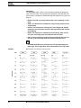
The filter is controlled by the parameters listed below:
•
•
•
•
•
•
•
•
BASE = FILTER BASE
WDTH = FILTER WIDTH
HPQ = HIGH PASS FILTER Q
LPQ = LOW PASS FILTER Q
ATK = FILTER ENVELOPE ATTACK
DEC = FILTER ENVELOPE DECAY
BOFS = FILTER BASE ENVELOPE OFFSET
WOFS = FILTER WIDTH ENVELOPE OFFSET
BASIC FILTER CONTROLS
The Track Effect System offers a resonant 24dB low/high/band-pass filter.
The parameters are untraditional, giving the user control of both the low and
high filter cut-offs, as well as a variable gap band-pass filter.
The Base parameter controls the base filter cut-off frequency. When the
Width parameter is set to its maximal value, changing the Base parameter
has the function of a high-pass filter.
The Width parameter controls the filter gap width, that is the distance
between the high pass and low pass cut-off frequencies. When the Base is
set to its minimum value, changing the Width parameter has the function of
a low-pass filter.
28
Monomachine SFX-6/60 USER’S MANUAL
TRACK EFFECTS
The HPQ and LPQ parameter controls the filter quality “Q” parameters. The
HPQ and LPQ values control how much the volume is boosted around the
high-pass and low-pass filter cut off frequencies.
The ATK and DEC parameters control the Filter Envelope Attack and Delay
speeds. The BOFS and WOFS parameters control how much of the
envelop amount will be added to the filter Base and Width parameters.
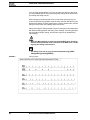
The filter envelope is trigged every time a FILTER-trig is received. This normally happens when a key has been pressed on the keyboard or the
[TRIG] keys, or played from the sequencer or received over MIDI. The FILTER-trig can be controlled individually from the sequencer, see section
“TRIG TRACKS” on page 48 for more information.
• To make a familiar “synth-bass” low pass filter bump each time the
note is trigged, set the WDTH to around 64, and turn up the WOFS to
around 32. Then turn the LPQ up until you get the amount of Low
Pass filter Q you prefer.
FILTER TRACKING
The Filter normally tracks the pitch of the note played. The high pass filter
start cut two octaves under the base pitch when the Base parameter is set
to zero.
Both the Base and the Width parameters rise one octave for eight steps.
This exact locking of the filter to octaves is useful if you want to use high filter Q settings to be used for pitch.
The filter tracking can be bypassed for the high pass and the low pass filter
individually. You find the controls for doing this on the Key assign in the
Assign window, see section “KEY TRACKING” on page 38 for more information.
• If you want to use the high pass filter Q as low frequency “loudness” boost, it is good to turn off the filter tracking parameter HPF.
Monomachine SFX-6/60 USER’S MANUAL
29
TRACK EFFECTS
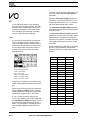
EFFECTS PAGE
In the Effects page you find the controls for the 1-band EQ, Sample Rate
Reduction, and the tempo-synchronised tape-style Delay.
The parameters of the effects page are listed below:
•
•
•
•
•
•
•
•
EQF = EQ FREQUENCY
EQG = EQ GAIN
SRR = SAMPLE RATE REDUCTION
DTIM = DELAY TIME
DSND = DELAY SEND AMOUNT
DFB = DELAY FEEDBACK
DBAS = DELAY FILTER BASE
DWID = DELAY FILTER WIDTH
EQ
Using the 1-band parametric EQ, you can boost or reduce a certain frequency band.
The frequency where the EQ will boost or reduce is controlled by the EQF
parameter.
The EQG parameter controls how much the EQ will boost (gain) or reduce
the signal around the EQF frequency. Positive values boost the signal and
negative reduce up to a maximum of 36dB.
• If you notice that the signal overload when you boost the signal you
might need to increase your headroom by decreasing the DIST
parameter on the Amplification page. Please see section “DISTORTION” on page 26 for more information.
SAMPLE RATE REDUCTION
The sample rate reduction effect resample the signal at a lower sample rate,
introducing alias effects which gives a digital “lo-fi” effect. The SRR parameter controls the amount of sample rate reduction down to a lowest of 2.8kHz.
• The Sample Rate Reduction often gives best effect on signals with
some, but not too much, high frequency contents. Sound with too
much high frequency information might introduce too much alias,
resulting in a very disharmonic signal.
30
Monomachine SFX-6/60 USER’S MANUAL
TRACK EFFECTS
DELAY
The Track Effect delay of the Monomachine is a single tap delay with realtime adjustable delay time. Some of its functionality can resemble tape
loops and solid state CCD delays. The delay time is always put in relation to
the global tempo setting.
The figure below outlines the function of the delay:
The Delay Send (“DSND”) parameter controls how high level of sound will
be let in to the delay loop from the audio signal of the track. To start get any
effect of the delay you need to first adjust Delay Send to some value other
than zero and generate some sound.
Delay send can be set to positive and negative values. For negative values
the stereo image of the signal will be preserved and for positive values it will
be switched left-right. The feedback loop will also be switched depending if
the Delay Send is set to positive or negative values. This means that you
should set negative Delay Send values to get delay with preserved stereo
image, and positive values for ping-pong delay.
The Delay Time (“DTIM”) parameter controls the delay time of the delay
loop. The actual delay time is relative to the current tempo, and it is measured in 1/256 notes. For instance, for a one beat delay (four 1/16 notes)
Delay Time should be set to 64.
When changing the Delay Time parameter or changing the tempo you will
hear the contents in the delay loop speed up or down to adjust to the new
tempo set. This behaviour allows the delay time parameter to be changed at
any time, without the typical digital crackle or brief silence usually experienced when adjusting delay time of digital delays.
• Try applying an LFO to the Delay time for interesting speed-modulating effects!
The Feedback (“DFB”) parameter controls how much of the delay output
sound will be fed back into the input of the delay. Using the Feedback you
can make delays with several or infinite “echoes”.
Monomachine SFX-6/60 USER’S MANUAL
31
TRACK EFFECTS
The Delay Filter Base (“DBAS”) and Delay Filter Width (“DWID”) parameters control the filter in the delay feedback loop. Using this you can make the
delay “echoes” sound sequentially different as the sound goes round the
delay loop.
• For using the delay for delay-line style sound sculpturing, try setting a very short Delay Time together with a Feedback above 32.
Then play around with the Delay filter settings.
• Watch your tweeters and ears! If the Delay Filter is not used to filter
the delay feedback signal, then Feedback values below 64 will cause
the sound in the delay loop to diminish over time, and values above
64 will cause the sound to grow until maximum audio level is
reached and then distort.
32
Monomachine SFX-6/60 USER’S MANUAL
LOW FREQUENCY OSCILLATORS (LFO’s)
LOW FREQUENCY OSCILLATORS (LFO’s)
Each of the 6 tracks in the Monomachine offers 3 interlaced low frequency
oscillators (LFO), which can be used to modulate any track parameter. A
typical application of an LFO is to let it sweep a filter cut-off frequency. The
18 interlaced LFO’s offer 11 waveforms and 5 trig modes. The LFO’s are
tied to their specific tracks, and are shared between the internal sequencer
and the midi sequencer. The speeds of the LFO’s are synchronized to the
global tempo.
First select a track using the [TRACK] keys that you want to alter the LFO’s
for. Then use the [DATA PAGE] keys to locate one of the three LFO pages.
All the three LFO’s of the track are identical. The <DATA ENTRY> LED’s
indicate which Data Entry page is currently selected, and the DATA ENTRY
encoders control the parameters of the Data Entry page selected.
LFO CONTROLS
The three LFO’s of each track are identical. They can control any parameter
of the track for the internal or the MIDI sequencer, as well as the other
LFO’s. The LFO control interface is printed below:
1. Page and Destination
2. Trig Mode
3. Waveform
4. Multiplier and Speed
5. Interlace
6. Depth
PAGE AND DESTINATION
The Page (“PAGE”) and Destination (“DEST”) parameters control which
parameter you wish the LFO to modulate. All seven Data Entry pages, plus
the MIDI Sequencer and the special Pitch page are accessible by the LFO.
On the Pitch page you will find 8 Destinations offering various ranges to
allow for both subtle vibrato and full range frequency sweeps.
• You can create complex modulations by letting an LFO control a
parameter of another one.
Monomachine SFX-6/60 USER’S MANUAL
33
LOW FREQUENCY OSCILLATORS (LFO’s)
TRIG MODE
The Trig mode switch (“TRIG”) is an important parameter for getting the
most out of the LFO's. The trig modes are described in the list below, and
their function is visualised in combination with the waveforms in Figure 3 on
page 32.
• FREE = The LFO is running continuously, never restarting or stopping.
• TRIG = The waveform is restarted for each LFO-trig, and then runs
continuously.
• HOLD = The waveform is running free in the background, but the
output LFO level is latched for each LFO-trig and held still until the
next LFO-trig.
• ONE = The waveform is restarted for each LFO-trig, then runs for
one cycle and finally stops and holds the last LFO level.
• HALF = The waveform is restarted for each LFO-trig, then runs for
one half cycle and finally stops and holds the last LFO level.
• In the Monomachine you can sequence LFO-trig separately from
other trigs. Check page 48 for more information on the Trig Tracks.
FIGURE 3.
Monomachine LFO waveform and Trig modes
34
Monomachine SFX-6/60 USER’S MANUAL
LOW FREQUENCY OSCILLATORS (LFO’s)
WAVEFORM
The Waveform selection switch (“WAVE”) select waveform for the LFO from
the eleven shapes available. There are 5 basic shapes plus mirrored copies
of all but the Random (“RND”) shape. Select the appropriate waveform with
the Waveform switch. The waveform shapes and their start and end LFO
levels are carefully selected to give a wide range of shapes in combination
with the trig modes. See the figure above for all possible combinations.
•
•
•
•
•
•
•
•
•
•
•
TRI = Triangular waveform
ITRI = Inverse Triangular waveform
SAW = Saw tooth waveform
ISAW = Inverse Saw tooth waveform
SAW = Saw tooth waveform
ISAW = Inverse Saw tooth waveform
EXP = Exponential Decay
IEXP = Inverse Exponential Decay
RMP = Linear Ramp
IRMP = Inverse Linear Ramp
RND = Random Levels
SPEED
The Multiplier ("MULT") and Speed ("SPD") parameters sets the LFO
speed relative to the master tempo. Speed is a linear controller that sets a
base speed that is multiplied with the Multiplier parameter. The use of both a
speed controller and a multiplier allows a very wide range of speeds, but still
provides a high degree of control. To get the finest resolution keep the Multiplier set as low as possible.
Increasing the Speed values gives shorter LFO cycle times. Each increase
of the Multiplier halves the LFO cycle time. For LFO speed synchronised to
straight beats, try setting Speed to 16, 32, 64 or 127. For example setting
the Multiplier to 2x and Speed to 64 gives a cycle time of sixteen 1/16 notes
(one full page).
INTERLACE
The Interlace (Parameter “INTL”) function is taken straight from the SidStation. Interlace is the process of alternating the LFO waveform with zero. The
speed of the zero-alternating cycles is controlled by the Interlace parameter.
The interlace is switched off when set to zero. Interlace can be particularly
interesting to use with trigged ramps with pitch as destination for creating
glittery rain-style effects.
DEPTH
The Depth (“DPTH”) is the amount of the LFO output level that is applied to
the target parameter. Setting Depth to 127 allows for modulating a parameter to and from any extreme value. For example, if the target parameter is
set to 64 a Depth setting of 64 is sufficient for modulating the target value to
its minimum (0) and maximum (127).
Monomachine SFX-6/60 USER’S MANUAL
35
LOW FREQUENCY OSCILLATORS (LFO’s)
• If you select the same destination for two different LFO tracks their
outputs will be added, making advanced layered LFO’s possible.
36
Monomachine SFX-6/60 USER’S MANUAL
ADDITIONAL KIT SETTINGS
ADDITIONAL KIT SETTINGS
This chapter deals with all kit settings not covered in the previous chapters.
ASSIGN
The Kit Assign allows the Joystick, Key velocity and Key position tracking to
be assigned to up to two Data Entry parameter of choice. This can allow for
a lot of dynamic depth of the sound with little effort.
You find the Assign window in the Kit menu. Press the [KIT] key and navigate to the Assign icon using the [CURSOR] keys, then press [ENTER/
YES] to enter the Kit menu.
In the Assign window you will find a minimum of four and a maximum of six
tabs. Navigate between the tabs using the [LEFT] and [RIGHT] keys. Use
the DATA ENTRY encoders to change settings of the parameters on the
tabs.
The Assign settings are applied per track. Select which track you want to
edit the assign for with the [TRACK] keys.
All tabs have two rows with three parameters in each in common. The Page
(“PAGE”) and Destination (“Destination”) parameters together select the
destinations for the assigns. Each of the destinations have an Add/Depth
(“ADD”) setting, which control how much of the control value that will be
applied to the destination parameter.
• The Page parameter selects between the seven Data Entry pages,
plus the special Pitch destination.
• The Destination parameter allows to select one of the eight parameters in the page.
• The Add/Depth parameter controls how much of the parameter chosen will affect the destination as maximum. The Add/Depth can be
set to positive and negative amounts.
• Setting Depth to +64 or -63 allows for modulating a parameter to any
extreme value. For example, if the target parameter is set to 64 a
Depth setting of +32 is sufficient for modulating the target value to
its maximum (127). If the target value is set to zero, a Depth setting
of +64 is needed for the target to be able to reach its maximum
value.
Monomachine SFX-6/60 USER’S MANUAL
37
ADDITIONAL KIT SETTINGS
• All Assign settings can be copied cleared and pasted using [FUNCTION] + [COPY] [CLEAR] and [PASTE]. All tabs are copied as a
whole, for easy transformation to other tracks or kits.
JOYSTICK
The first two to four tabs contain the parameters for the joystick.
The first tab can control the right or the left, or both right and left directions of
the joystick, depending of the value of the MIRR = Mirror parameter.
• If Mirror is set to OFF, the right and left directions of the joystick
have individual parameter pages named “JOY R” and “JOY L”.
• If Mirror is set to ON, the right and left directions get the same settings. The parameters of the “JOY RL” page are applied to the right
direction, and inverted for the left.
The “JOY U/D” tab has the same function as the “JOY R/L” just described,
but controls the assign for the up and down directions of the joystick.
• Information for the SFX-60 module, and for controlling the SFX-6
externally: The Joystick is mapped to Pitch bend for left and right
directions, Modulation Wheel (CTRL_CHANGE#1) for upward direction and Breath controller (CTRL_CHANGE#2) for downward direction.
VELOCITY
The “VEL” tab controls the assignments for Key velocity. Key velocity is the
name for how hard the key is played on the keyboard, or more correctly, the
amount of time it takes from the key is pressed until it reaches the base. No
parameters additional to the Destination and Add/Depth are found here.
• The key velocity control is mainly for live keyboard playing or
sequencing with an external sequencer. The internal sequencer
always plays notes with velocity set to 100. Volume and other
parameters are instead usually controlled with the parameter locks.
KEY TRACKING
The “KEY” tab controls the assignment for Key Tracking. The Key Tracking
is connected to the note index from the last key pressed. For example, if C1 was pressed, the Key Tracking value will be low, and if C-8 was pressed it
would reach almost its maximum value.
38
Monomachine SFX-6/60 USER’S MANUAL
ADDITIONAL KIT SETTINGS
There are two additional parameters on the Key Tracking controlling if the
high pass and/or low pass filter should automatically track the pitch.
• The HPF = High Pass Filter Tracking parameter set to OFF disconnects the standard filter tracking of the high pass filter.
• The LPF = Low Pass Filter Tracking parameter set to OFF disconnects the standard filter tracking of the high pass filter.
See page 28 for more information on the filter.
TRIG TRACK SETTINGS
The Trig Track Settings is a group of parameters which affect the way certain aspects of the sound in the track are trigged.
You find the Trig track window in the Kit menu. Press the [KIT] key and navigate to the TRIG track icon using the [CURSOR] keys, then press [ENTER/
YES] to enter the Trig track menu.
In the Trig track window you will find five parameters. Navigate between the
parameters using the [UP] and [DOWN] keys. Use the [LEFT] and [RIGHT]
keys to adjust the parameter values.
TRIG POS
The Trig pos parameter allows you to forward the notes being played to the
current track to another.
For example, if you edit Trig Pos for “Track 1”, and set it to point to “Track 3”,
then Track 3 will also play notes that are sent to Track 1.
• You can link Trig Pos, so that several tracks can be trigged from
one.
TRIG PORTAMENTO
The Trig Portamento switch has two options:
• Always: the portamento will always be active, gliding between all
notes played.
• Only legato: the portamento is active only when playing overlapped
so called legato notes.
LEGATO TRIG MODES
The three parameters at the bottom of the window control which of the AMP,
FILTER and LFO trigs will be active for notes played legato.
Monomachine SFX-6/60 USER’S MANUAL
39
ADDITIONAL KIT SETTINGS
• For a staccato bass sound it is useful for all trigs to be activated, so
the sound will sound the same, even if two notes are played overlapped by mistake. But for a lead sound it might be better to not initiate any trigs for notes played legato.
MULTI TRIG
The Multi Trig is a link between the synthesis and the sequencer of the Monomachine. Using the keyboard Multi Trig mode on the SFX-6, or the Multi
Trig MIDI channel (see section “MULTI TRIG CHANNEL” on page 90 for
more information) you can make advanced monophonic arrangements. All
tracks can unite their efforts in creating one dynamic sound, and the
sequencer can be part of the arrangement.
You find the Multi Trig settings window in the Kit menu. Press the [KIT] key
and navigate to the MULTI trig icon using the [CURSOR] keys, then press
[ENTER/YES] to enter the Multi Trig window.
In the Multi Trig window you will find one main tab named “MULTI MODE”
with four options. To the right there is room for an additional context tab with
extra settings for some selections of the first tab. Navigate between the
tabs, and inside the context tab (when available) using the [LEFT] and
[RIGHT] keys. Use the [UP] and [DOWN] keys to adjust the parameter values. Selections in the Multi mode tab need to be confirmed with the
[ENTER/YES] key, whereas the selections in the context tab are effecting
immediately.
•
•
•
•
ALL TRK = All Track
SPLIT MODE = Split Mode
SEQ START = Sequencer Start
SEQ TRNSP = Sequencer Transpose
MULTI TRIG ALL TRACK
Setting the Multi Trig mode to All Track makes the Multi Trig channel control
all six tracks at once. Note events received on the Multi Trig channel will be
distributed to all six tracks for parallel mono operation. The joystick controllers, velocity and key tracking will control all tracks simultaneously, as
assigned in the Assign window (see page 37). The Multi Env is applied to
the All Track Multi Trig mode (see page 42).
There is no context tab for the All Track selection.
40
Monomachine SFX-6/60 USER’S MANUAL
ADDITIONAL KIT SETTINGS
• All arpeggiators of the tracks retain their function in the All Track
Multi Trig mode. Interesting results can be yield with different
arpeggiator settings and speeds for the tracks that then are activated in parallel from the Multi Trig channel.
MULTI TRIG SPLIT MODE
The Split mode allows you to split the keyboard in two zones, each one controlling a part of the tracks by the upper and lower part.
There is an additional tab for the split mode, named “ZONES”. From the
Zones tab you control which tracks will be devoted to the upper and the
lower part of the keyboard, and where the split point is located on the keyboard.
The TRACK parameter controls which will be the first track to be controlled
by the upper part of the keyboard. All tracks above this one will be controlled
by the upper part and the rest by the lower.
The KEY parameter controls which key is the first to control the upper part
of the tracks. All keys above this one will be directed to control the upper
section of the tracks.
MULTI TRIG SEQUENCER START AND SEQUENCER TRANSPOSE
Sequencer Start (“SEQ START”) and Sequencer Transpose (“SEQ
TRANSP”) are two modes of the Multi Trig which invoke the sequencer for
creating advanced monophonic soundscapes or looped melodies for realtime manipulation.
• The Sequencer Start mode makes the sequence restart for each note
played. The sequence will be transposed based on which note is
played. The original pitch will be invoked on C-4. The Multi Env is
trigged when notes are played (see page 42).
• The Sequencer Transpose mode starts and transposes the
sequence for the first note received on the Multi Trig channel. Subsequent notes will only transpose the sequence and trig the Multi
Env, so that the sequence loop is never broken.
The action of the Sequencer Start and Sequencer Transpose modes can be
delayed to an even bar of the loop. This is controlled by the context menu
named “TIMING”. If you want to stay in the beat, set the Timing parameter to
what you prefer. A setting of 16/16 delays the action until a full page of 16
trigs is played (four beats) in single speed mode.
Monomachine SFX-6/60 USER’S MANUAL
41
ADDITIONAL KIT SETTINGS
MULTI ENV
The Multi Env is an additional envelope applied to all the tracks in the Multi
Trig modes excluding the Split Mode. You reach it by pressing both the
[DATA PAGE] keys simultaneously.
The Multi Env is an envelope that is applied on top of the track envelopes,
allowing all the tracks to be treated as one massive monophonic track.
It is a standard Attack (“ATK”), Decay (“DEC”), Sustain (“SUS”), Release
(“REL”) envelope. An additional Portamento (“PORT”) parameter is also
available. Control the Multi Env parameters using the DATA ENTRY encoders.
Sound played on the individual tracks while the Multi Trig is active will be
under the influence of the Multi Env, so the sound level might be lower than
usual.
If you prefer to let the effect of the Multi Env be inaudible, apply settings of
Attack=0, Decay=127, Sustain=127 and Release=127.
Note that you will only hear the effects of the Multi Env when sound
are played from the Multi Trig channel, and not from the split mode!
42
Monomachine SFX-6/60 USER’S MANUAL
THE PATTERN SEQUENCER
THE PATTERN SEQUENCER
The pattern step sequencer is a central part of the Monomachine sound. It is
designed to be an inspirational tool for pattern based music, or a component
in the creation of dynamic multi-track monophonic sounds.
The sequencer is designed both for live and studio use. The patterns can
either be trigged individually from the user interface or by MIDI commands
or they can be linked together with pattern chaining or in song mode.
The sequencer has several modes of operation, in this chapter we will start
by looking at the Pattern mode.
First make sure that the <PATTERN> LED is lit and the <SONG> LED is
unlit. If necessary toggle it by pressing the [PATTERN/SONG] key. Also
check that the <MULTI TRIG> LED is unlit so that you are not in Multi Trig
mode. If necessary, toggle it by pressing the [MULTI TRIG] key. For external
control we recommend using the MIDI Auto Track Channel (see section
“AUTO TRACK CHANNEL” on page 90). On the SFX-60 you can use an
external MIDI keyboard on this channel when we refer to the Keyboard.
PATTERN SELECTION
The Monomachine offers 8 banks with 16 patterns in each. The banks are
named by the index A,B,C,D,E,F,G,H. The [BANK GROUP] key selects
between pattern bank groups A to D and E to H. The <BANK GROUP>
LED’s indicate the current bank group selection.
To select a pattern, press and hold the bank key while pressing a [TRIG]
key. For selecting pattern A05, first make sure the bank LED’s indicate that
bank group A to D are selected, then press and hold key [A/E] while pressing [TRIG] key 5.
While the [BANK] keys are pressed you can tell which patterns are uninitialised by the 16 <TRIG> LED’s. LED’s that are red indicate that the corresponding pattern contains data.
If pattern selection is done while the sequencer is playing, the selected pattern will not be active until the current pattern has played to its end. You will
see the index of the pattern next to be changed to the right of the current
pattern. Until it has been switched it is blinking with an arrow pointing to the
left.
Monomachine SFX-6/60 USER’S MANUAL
43
THE PATTERN SEQUENCER
COMPOSING A PATTERN
This chapter will take you through the details how to create a pattern in grid
composing and live recording mode.
RECORDING PREPARATIONS
Follow the steps below before continuing with any pattern composing. It will
put the Monomachine in base pattern edit mode.
1. Close all windows that might be open using the [EXIT/NO] key.
2. For SFX-6: Check that the <MULTI TRIG> LED is unlit. Press the [MULTI
TRIG] key to switch it off if needed.
3. Check that one and only one of the <DATA ENTRY> LED’s are lit. If the
four top LED’s are lit you need to exit the MIDI Sequencer edit mode by
pressing [MIDI SEQ] while holding [FUNCTION].
4. Select a pattern as described in section “PATTERN SELECTION” on
page 43. We recommend starting with a clear pattern. All patterns in
banks E-H are clear as factory default.
5. Select a kit for the pattern as described in section “LOADING A KIT” on
page 19.
6. Select the track you wish to edit using the [TRACK] keys. Check that the
track makes sound by trigging it using either the Keyboard or the [TRIG]
keys.
7. Verify that all the <TRIG TRACK> LED’s are lit. Press the [TRIG
SELECT] key to cycle until all <TRIG TRACK> LED’s are lit if needed.
GRID COMPOSING
Grid composing is a method of percussion composing that first was developed in vintage drum machines. In the Monomachine it has been adapted
and extended to fit for intuitive pattern based arrangements of melodies and
rhythms. In the default grid composing state, the 16 [TRIG] keys represent 1
page of 1/16 notes.
1. Perform the Recording Preparations as described in the previous section.
2. Enter grid composing mode by pressing the [RECORD] key. The
<RECORD> LED above the key should now be firmly lit.
3. You can press [PLAY] if you prefer to listen to the pattern playing while
composing. It will loop over and over, until you press [STOP] to stop the
playback or [PLAY] to pause it.
4. Press a [TRIG] key to set a note trig for the corresponding step. The
<TRIG> LED’s indicates which steps contain note trigs. You will see that
the LED above the [TRIG] key lights up with a red light as you press it.
You can remove a note trig by pressing the corresponding [TRIG] key
one more time. The LED should now be switched off.
44
Monomachine SFX-6/60 USER’S MANUAL
THE PATTERN SEQUENCER
5. While holding a [TRIG] key you can see a mini-keyboard appearing after
a short delay. It is located in the lower left corner of the LCD interface.
This mini-keyboard indicates the pitch of the note, both by a marking on
the mini-keyboard and printed below. The <KEYBOARD> LED’s of the
Monomachine also indicate the pitch programmed.
6. There are two methods for adjusting the pitch of a trig. You can either
press a key on the Keyboard while holding the [TRIG] key to set the
pitch indicated by the Keyboard key. You can also use the [CURSOR]
keys to adjust the pitch programmed while holding the [TRIG] key. Holding [FUNCTION] while pressing the [RIGHT] or [LEFT] key adjusts the
pitch one full octave up or down.
7. You can set NOTE_OFF trigs by pressing the [TRIG] key while holding
[FUNCTION]. NOTE_OFF trigs are events that tell that the key is lift up,
starting the Release phase of the Amplitude Envelope (see page 25).
NOTE_OFF are indicated with yellow <TRIG> LED’s.
8. Chords can also be programmed. These can be used for Poly mode (see
section “POLY MODE” on page 68) and trigging the arpeggiator (see section “THE ARPEGGIATOR” on page 59). If not in Poly mode and if the
Arpeggiator is not activated, only the base pitch will sound. You can program chords with the Keyboard by pressing more keys while holding the
first base pitch key. The mini-keyboard shows chord-notes as dots. A
scroll list will appear below the mini-keyboard and the base pitch. This list
can also be edited using the [CURSOR] keys. Press [ENTER/YES] to
enter the list if no chord key yet is entered.
• In the Monomachine, you work directly in the pattern memory. There
is no need to save patterns. If you wish to keep the pattern intact
you will have to copy it to another pattern before you begin editing
Monomachine SFX-6/60 USER’S MANUAL
45
THE PATTERN SEQUENCER
it. See section “FULL PATTERN COPY” on page 54 for more information on copying patterns.
• In grid composing mode, pressing keys [LEFT] and [RIGHT] while
holding [FUNCTION] rotates the pattern.
• You can avoid general need of NOTE_OFF trigs by making good use
of the Hold parameter (see section “AMPLIFIER ENVELOPE” on
page 25).
• Depending on the scale setup, you might have a longer pattern than
what is possible to edit with the 16 LED’s and [TRIG] keys. In that
case, you need to use the [SCALE] key to change between the
pages. See section “SCALE, PAGES AND TIME SIGNATURES” on
page 51 for more information.
LIVE RECORDING
The second method of recording notes in the sequencer is by recording
them live while playing. You can record both from the Keyboard and the
[TRIG] keys.
1. Begin with following the instruction in section “RECORDING PREPARA-
TIONS” on page 44.
2. To start recording in live recording mode, hold [RECORD] while pressing
[PLAY]. This starts the sequencer recording and the record LED will start
flashing.
3. You can now play notes on the Keyboard or the [TRIG] keys, and they
will be quantised and recorded to the closest trig step in the pattern.
4. If a note is played on a step where there already was a note programmed
the new note will replace the old note.
5. Chords can also be recorded in the sequencer. They will only make effect
when in Poly mode (see section “POLY MODE” on page 68) or when the
Arpeggiator (see section “THE ARPEGGIATOR” on page 59) is active.
6. To erase notes on live recording mode hold [EXIT/NO] while the notes
you want to remove are heard.
7. The pattern will loop and be ready for further recording until you press the
[STOP] key.
• All live recorded data will be quantised to the current scale resolution (1/16 or 1/32 notes).
• If you want to edit the recorded notes, you can use grid compose as
described in section “GRID COMPOSING” on page 44.
PARAMETER LOCKS
One major advantage of the Monomachine is the straightforward method to
lock parameter settings to specific trigs steps. This function is named
Parameter Locks. Parameter locks can be programmed in both Grid Com-
46
Monomachine SFX-6/60 USER’S MANUAL
THE PATTERN SEQUENCER
posing mode and Live Recording mode. All parameters of the Data Entry
pages can be locked. Parameter locks are an important tool for creating
unique dynamic loops with the Monomachine.
PARAMETER LOCKS IN GRID COMPOSING MODE
To program parameter locks in grid composing mode, follow the steps
below.
1. Begin with following the instruction in section “RECORDING PREPARA-
TIONS” on page 44.
2. Enter grid composing mode by pressing the [RECORD] key. The
<RECORD> LED above the key should now be firmly lit.
3. Press and hold a [TRIG] key for the step where you want to add a lock.
Note that if there is a trig already set for the step it is not removed if you
keep the [TRIG] held down until you see the mini-keyboard.
4. While holding the [TRIG] key, you can now tweak the parameter of your
choice with the DATA ENTRY encoders. You can tell that the parameter
has been locked by the parameter being inverted on the LCD. You can
also click an unlocked parameter once to lock it to its current value. When
the [TRIG] key is released, the trig for that step will hold the parameters
that you just programmed. The parameter will be held until a new trig is
played.
5. If you want to view the current parameter lock settings for a step, hold the
[TRIG] key until you see the mini-keyboard appear. You can tell which
parameters are locked by them being inverted.
6. Remove a single parameter lock by clicking the DATA ENTRY key while
holding the [TRIG] key.
7. To remove all parameter locks for a step, remove the trig by pressing its
corresponding [TRIG] key. Then insert it again by pressing it again. You
can also delete the trigs for the step by holding the [TRIG] and press the
[CLEAR] key.
8. You can copy a trig step, including pitch and all parameter locks. To do
this, press and hold the [TRIG] key for the step you want to copy, and
press the [COPY] to perform the note copy. Then hold the [TRIG] key for
the step you want to paste the trig to, and press [PASTE] to perform the
paste note operation.
• In grid composing mode, you can verify which steps have parameter
locks by looking at the <TRIG> LED’s. A firmly lit <TRIG> LED
means that the corresponding step has no parameter locked,
whereas a rapid interval flash indicates it does have one or many
parameter locks.
Monomachine SFX-6/60 USER’S MANUAL
47
THE PATTERN SEQUENCER
• More than one parameter can be locked on a track specific step.
Other tracks can have locks on the same step as well. A pattern can
have a total of 62 parameter-tracks that carries independent locks.
• A lock is a snapshot of a parameter setting. It changes the parameter value from its original value stored in the kit, but only for that
note trigging. The parameter will change back to its default state for
the next trig if no further parameter locks are made for that note and
parameter.
PARAMETER LOCKS IN LIVE RECORDING MODE
In live recording mode, you can record parameter locks in real-time. To do
this, follow the steps below:
1. Begin with following the instruction in section “RECORDING PREPARA-
TIONS” on page 44
2. To start recording in live recording mode, hold [RECORD] while pressing
[PLAY]. This starts the sequencer recording and the record LED will start
flashing.
3. Record parameter locks by adjusting the corresponding DATA ENTRY
knob while the sequencer is playing and recording. When changing a
parameter, the parameter lock will be set to the next trig step played on
the track. If a parameter is not changed between two trigs no parameter
lock will be recorded for that step.
4. To remove parameter locks you need to enter Grid Composing mode and
follow the instructions in “PARAMETER LOCKS IN GRID COMPOSING
MODE” on page 47
• It is often a good idea to edit and fine tune the parameter locks in
grid composing mode, after recording them in live recording mode.
ADVANCED SEQUENCER CONTROL
For users that seek the most control over the music creation control the
Monomachine offer unique sequencer features for fine tuned sequencing.
The extended functionality fits into a familiar environment, so it is very possible to use the SFX-6/60 with great reward without mastering the features
described here. We do suggest though that you take some time to study this
section after you have familiarised yourself with the other aspects of the
Monomachine.
TRIG TRACKS
Monomachine extends the traditional concept of sequencer control. With the
SFX-6/60 you can separate pitch sequencing from envelope trigging and
parameter locks. For each track you have access to three individual sub
48
Monomachine SFX-6/60 USER’S MANUAL
THE PATTERN SEQUENCER
tracks named Trig Tracks, offering individual control over Amplitude Envelope, Filter Envelope and LFO trigs.
Traditionally synthesizers retrig all envelopes when a NOTE_ON event (a
key pressed on the keyboard) is played. In the Monomachine the
NOTE_ON events can be split up, allowing you to trig the Amplitude envelope (AMP Trig), Filter Envelope (FILTER Trig) and LFO (LFO Trig) at any
step of the sequencer you prefer. Please refer to the first two illustrations in
figure “Trig Track illustrations” on page 50. The second illustration is the
Monomachine equivalence of the traditional pattern in the first one.
The [TRIG SELECT] key cycles between which Trig Track is programmed
from the [TRIG] keys, and the <TRIG TRACK> LED’s indicate the current
selection. All three <TRICK TRACK> LED’s lit means the ALL mode, where
trigs for all three Trig Tracks are set. The four states are listed below:
• ALL - This is the default state where all <TRIG TRACK> LED’s are lit.
[TRIG] keys pressed add or remove trigs on all three Trig tracks, and
a pitch is added as default.
• AMP - [TRIG] keys pressed only add or remove trigs on the AMP Trig
track. No pitch is added as default.
• FILTER - [TRIG] keys pressed only add or remove trigs on the FILTER Trig track. No pitch is added as default.
• LFO - [TRIG] keys pressed only add or remove trigs on the LFO Trig
track. No pitch is added as default.
When Trig Track AMP, FILTER or LFO is selected, the <TRIG> LED’s are lit
red if a trig is set for the corresponding step on the Trig Track selected. The
<TRIG> LED’s are green if the trig is not set for the Trig Track selected, but
on some other Trig Track (or if it has a Trigless Trig, see section “TRIGLESS
TRIGS” on page 49).
When Trig Track ALL is selected, the <TRIG> LED’s are lit red if a trig is set
on all AMP, FILTER and LFO Trig Tracks. If one or more of them are missing
then it is lit green. Steps with NOTE_OFF events are lit yellow.
TRIGLESS TRIGS
It is possible to change pitch or make parameter locks, even without trigging
any envelopes. But since pitch and parameter locks are set with a [TRIG]
key pressed, and trigs are added when the [TRIG] key is pressed you need
to insert a Trigless Trig first.
The quickest way to do this is to press the [TRIG] key twice while holding
[FUNCTION]. The corresponding <TRIG> LED will then first turn yellow
(NOTE_OFF) and then green which indicates it is a Trigless Trig. You can
Monomachine SFX-6/60 USER’S MANUAL
49
THE PATTERN SEQUENCER
now hold the [TRIG] key and program a pitch or parameter lock as normal,
but no envelopes will be trigged. You can add these later using the Trig
Track functions as described in the previous section.
Normal trigs can also be converted into Trigless Trigs by removing the AMP
FILTER and LFO trigs manually using the Trig Track functions.
PITCHLESS TRIGS
You can easily remove the pitch from a trig by pressing [EXIT/NO] while
holding the [TRIG] key. The pitch from the previous note will then continue
to sound for the trig.
FIGURE 4.
Trig Track illustrations
50
Monomachine SFX-6/60 USER’S MANUAL
THE PATTERN SEQUENCER
SUMMARY
All the features and methods in this section can be summed up in the conclusions that any pitch programming, Amplitude, Filter and LFO trigging and
parameter locks can be performed free at will at any step of the pattern.
Please refer to the third illustration of figure ”Trig Track illustrations” for an
example of a Monomachine pattern using all the features mentioned in this
section. Only the trig on the first step is equivalent to a normal NOTE_ON.
THE LINK BETWEEN KITS AND PATTERNS
Each pattern with data is associated with a certain kit, which will be recalled
when the pattern is played. This way, you know playing a certain pattern
always gives the same result, and that the parameter locks make sense.
• Be careful to save any changes you have made to your kit that you
want to keep. Changing pattern might change kit and then you will
lose the old kit settings.
• If two patterns use the same kit, the kit will not be reloaded when
changing pattern.
SCALE, PAGES AND TIME SIGNATURES
By default the length of a pattern is 4/4 bars, built from 16 steps. 16 steps
can be reached from the [TRIG] keys at once. We refer to these 16 steps as
one Page. A pattern can be extended to up to 64 steps, which forms a maximum of four pages. All tracks share the same scale length, and are always
played in sync.
The default scale length is 16 which gives a time signature is 4/4. Setting the
scale length to 32 gives the double length of the pattern with 4/4 signature. If
you want to use a time signature of 3/4 you need to set the scale length to a
division of 12.
In grid composing The [TRIG SELECT] key is used to cycle between the
active pages, and the <TRIG PAGE> LED’s indicate which one is currently
being edited. When not in grid composing mode the LED’s for the available
pages for the track is lit with a steady light. The LED for the page currently
played is flashing.
SCALE SETUP
Press the [SCALE SETUP] key while holding [FUNCTION] to open the
SCALE SETUP window. From here you can set the scale length and playback speed of the pattern currently selected.
Monomachine SFX-6/60 USER’S MANUAL
51
THE PATTERN SEQUENCER
There are three parameters available in the SCALE SETUP window. The
underlined focus is moved with the [LEFT] and [RIGHT] keys.
1. The first parameter sets the total number of steps of the pattern. When in
focus, use [UP] and [DOWN] to increase/decrease the number of steps.
The LEVEL encoder is also controlling this parameter, and the [TRIG]
keys can be used as well to set the end step.
2. The second parameter sets the scale length in divisions of 16 (one full
page). If the scale length is higher than 16 the [SCALE] key need to be
used in grid composing mode to toggle the focus of the [TRIG] keys
between the pages.
3. The third parameter is the tempo multiplier. It allows a pattern to be
played back 200% of the global tempo. This is for increasing the step resolution to 1/32 notes. There are two possible settings, “1X” and “2X”.
• Even though you set a pattern to have a certain length using scale
setup, you can change this row by row in the song editor. See section “THE SONG SEQUENCER” on page 73 for more information.
• The [SCALE] key offers a quick way to cycle the scale length in
steps of 16.
• When changing the scale length so more pages come in use, lower
pages will automatically be copied to higher, but only if nothing so
far has been programmed on the pages added. Pages can also be
manually copied, see section “PAGE COPY” on page 57.
TEMPO
The tempo in the Monomachine is a global parameter. It is however not
stored in the Global slots (see page 87). The tempo will naturally control the
playback speed of the patterns, but also control various parameters in the
Monomachine, such as the Hold parameter, the Delay and LFO speeds and
some machine parameters.
The tempo is controlled from the Tempo screen, and can also be set in the
Song Sequencer.
THE TEMPO SCREEN
The tempo screen is called by pressing the [TEMPO] key.
From here you can use the LEVEL encoder to change the current tempo in
integer steps. The [UP] and [DOWN] arrow keys change the decimal part of
the tempo. Holding [FUNCTION] while editing the tempo will delay the
change of tempo until you release the [FUNCTION] key.
52
Monomachine SFX-6/60 USER’S MANUAL
THE PATTERN SEQUENCER
TAP TEMPO
To tap a tempo, hold the [FUNCTION] key and tap the [TEMPO] key at a
steady rhythm.
After four consecutive taps the average tempo of the taps will be set as the
current tempo and it will be showed in the tap tempo window. You can continue taping the [TEMPO] key, and the taps will be used for refine the average tempo. A maximum of 16 tempo taps are considered.
EXTERNAL SYNCHRONISATION
The Monomachine can be set to either internal or external synchronisation.
When in internal clock mode the SFX-6/60 outputs a high quality MIDI clock
on the MIDI OUT port. This can be used for keeping external gear in sync
with the Monomachine.
When in external midi clock synchronisation mode the Monomachine will
stay in sync with an external MIDI clock if present. When in external clock
mode the tempo in the upper left corner of the base LCD screen will show
“EXT” for external synchronisation. The tempo screen will show the current
average tempo. The tempo displayed in the tempo screen is only an average calculation. Even though it might appear to vary the Monomachine is
tightly locked to each MIDI clock signal received.
Read more about how to set the external synchronisation of the Monomachine in section “CONTROL IN” on page 92.
• The tempo is not stored in patterns or kits. However, songs can
store tempo changes.
PATTERN CHAINING
You can use pattern chaining to cue up patterns to be played after each others in a loop, like a simple live sequencer for patterns. In pattern mode, hold
a [BANK] button and then press the [TRIG] key for the pattern you want to
be first in the chain. As long as you keep the first [TRIG] key down, subsequent [TRIG] keys pressed will add patterns to the end of the chain. It is
only possible to chain patterns from one bank, and each pattern may only be
chained once.
Monomachine SFX-6/60 USER’S MANUAL
53
THE PATTERN SEQUENCER
Chaining is indicated by a double arrow between the current and the next
pattern.
[STOP] will reset the pattern chain to the beginning. Pressing [STOP] twice
will exit the pattern chaining and return to normal operation. Selecting a new
pattern exits pattern chaining as well.
PATTERN COPY CLEAR PASTE
Copy, clear and paste is a vital part of song composing, and it is important to
have the right function close at hand. The Monomachine offers many types
of copy, clear and paste functions through the [FUNCTION] + [COPY],
[CLEAR] and [PASTE] keys. This section will deal with the copy, clear and
paste functions in pattern mode.
• All clear and paste operations can be undone if the clear or paste
function is repeated immediately after if was first performed.
FULL PATTERN COPY
To copy the contents of a full pattern to another, follow the steps below.
1. Make sure that the “RECORD” LED is not lit, so you are not in grid com-
posing mode.
2. Select the source pattern. Hold [FUNCTION] and then press [COPY]. A
message “COPY PATTERN” will be shown in the display.
54
Monomachine SFX-6/60 USER’S MANUAL
THE PATTERN SEQUENCER
3. Change pattern to the destination where you wish to paste your pattern
data.
4. Paste the data by holding [FUNCTION] and then pressing the [PASTE]
key. A message “PASTE PATTERN” will be shown in the display.
5. The pattern can also be cleared by holding [FUNCTION] and then press-
ing [CLEAR]. A message “CLEAR PATTERN” will be shown in the display.
• Pasting data into a pattern overwrites any previous data in the pattern.
• The pattern data that is copied consists of notes, parameter locks,
the kit association, MIDI sequencer notes and Arpeggiato, Transpose, Swing and Slide settings for all six tracks.
• Pattern clear clears everything mentioned above, but the kit association.
TRACK COPY
In grid composing mode, it is possible to copy the contents of one track to
another.
1. Make sure the “RECORD” LED is steady lit, so you really are in grid com-
posing mode. Select the source track using the [TRACK] keys.
2. Hold [FUNCTION] and press [COPY] to copy the data of the track. A
message “COPY TRACK” will be shown in the display.
3. Select another destination pattern if preferred, and select track using the
[TRACK] keys.
4. Paste the data into the new track by pressing and holding [FUNCTION]
and then pressing the [PASTE] key. A message “PASTE TRACK” will be
shown in the display.
5. The track can also be cleared by holding [FUNCTION] and then pressing
[CLEAR]. A message “CLEAR TRACK” will be shown in the display.
Monomachine SFX-6/60 USER’S MANUAL
55
THE PATTERN SEQUENCER
• Pasting data into a track overwrites any previous data.
• The track data copied consists of notes, parameter locks, the
machine selection, Data Entry pages and Arpeggiato, Transpose,
Swing and Slide settings. Note that track copy alters the kit.
SUPER COPY
For Track, Pattern and Machine copy/clear/paste, the default action can be
exchanged. Hold the [FUNCTION] and [COPY] for around a second and
the default message-box will expand to a larger one including a selection
box.
You can now release function while holding [COPY]. While still holding
[COPY], use the [UP] and [DOWN] keys to manoeuvre the inverted selection box. When [COPY] is released the selected copy action will be performed.
• The Track and Pattern selections are known from the previous sections.
• Melody copy is a special copy function which copies all pitch data
from the track, but excludes parameter locks and machine selection
and settings. Use this to transport a melody between tracks you are
using different machines for.
• The machine selection is a shortcut for copying the machine selection and all Data Entry pages, which is normally performed from the
EDIT KIT window.
Paste works analogue to the copy just described. Note that you can only
reach the super copy selections from Pattern, Track and Machine copy.
The Super Clear function works analogue to the copy and paste, with the
difference that Melody is exchanged for Clear Locks. Selecting Clear Locks
will erase all Parameter locks for the track.
• All Super Copy functions are delayed until the [COPY], [CLEAR] or
[PASTE] key is released. So even if you get the message “PATTERN
CLEAR” it is not performed until the [COPY], [CLEAR] or [PASTE]
key is released, so that you get the chance to change the default
action in the selection box. This delay is only valid for Copy/Clear/
Paste for Pattern, Track and Machine, which will invoke super copy.
• You can cancel Super Copy/Clear/Paste with [EXIT/NO].
56
Monomachine SFX-6/60 USER’S MANUAL
THE PATTERN SEQUENCER
NOTE COPY
Individual note steps, including chords and parameter locks, can be copied
and pasted. Hold the [TRIG] key for the step you want to copy and press
[COPY]. Release the keys and then hold the [TRIG] key for the step you
want to paste the note to and press [PASTE].
If you hold a [TRIG] and press [CLEAR] all parameter locks will be cleared.
PAGE COPY
In Grid Composing mode you can copy, clear and paste individual track
pages of 16 steps each. This can be handy when working with scale lengths
above 16. See section “SCALE, PAGES AND TIME SIGNATURES” on
page 51 for more information on how to set Scale length and more information about pages.
To perform Page Copy, make sure you are in Grid composing mode, and
press [COPY] while holding [SCALE]. The current page (the 16 steps
accessible by the [TRIG] keys) will be copied into the Page copy buffer. Use
the [SCALE] key to cycle to the destination page and then press [PASTE]
while holding [SCALE]. Page clear is performed analogue by pressing
[CLEAR] while holding [SCALE].
Page Copy operates on trigs, pitches and parameter locks.
Monomachine SFX-6/60 USER’S MANUAL
57
THE PATTERN SEQUENCER
58
Monomachine SFX-6/60 USER’S MANUAL
ADDITIONAL SEQUENCER FEATURES
ADDITIONAL SEQUENCER FEATURES
THE ARPEGGIATOR
Each track of the Monomachine (including the MIDI sequencer tracks) offers
an advanced arpeggiator. The arpeggiator is a note processor that generates rhythmic note patterns that is generated from the arpeggiator settings
and the notes pressed. Most commonly arpeggiators are used for making
automated real-time monophonic cycled notes based on the chord played.
Each pattern offers 12 arpeggiators, one per track. The arpeggiator window
is called by pressing [ARP] while holding [FUNCTION]. Select which track
you want to edit the arpeggiator for using the [TRACK] keys. Use [MIDI
SEQ] while holding [FUNCTION] to edit the MIDI sequencer arpeggiators
(see page 59 for more information on the MIDI sequencer).
ARPEGGIATOR BASIC SETTINGS
The main Arpeggiator interface is printed below:
The top four parameters are controlled using the four upper DATA ENTRY
encoders.
•
•
•
•
SPD = SPEED
MODE = MODE
PLAY = PLAY DIRECTION
RNGE = OCTAVE RANGE
Assuming you start with a uninitialised arpeggiator, you need to change the
Mode from the default “OFF” setting to activate it.
The Speed parameter controls the speed the notes are played by the
arpeggiator, or more precisely the delay between two consecutive notes. A
Speed setting of 6 equals one 1/16 note, 12 equals 1/8 and so on.
The Mode parameter selects between four modes:
• OFF - Inactivates the arpeggiator.
• KEY - The arpeggiator operates on the keys currently played.
• SID - Keys stay in the arpeggiator even after NOTE_OFF. Single keys
do not activate the arpeggiator.
• ADD - Keys are added into the arpeggiator as long as at least one
key is pressed.
Monomachine SFX-6/60 USER’S MANUAL
59
ADDITIONAL SEQUENCER FEATURES
See section “ARPEGGIATOR MODES IN DEPTH“ for more information on
the arpeggiator play modes.
The Play Direction parameter selects between five modes:
• TRUE - The arpeggiator plays the notes in the same order they were
played.
• UP - The arpeggiator sorts the notes and plays them upwards, in rising order.
• DOWN - The arpeggiator sorts the notes and plays them downwards, in descending order.
• CYCLE - The arpeggiator sorts the notes and plays them cycling
first upwards then downwards.
• RND - The arpeggiator plays the notes in random order.
If the Range parameter is set higher than the default “1 OCT”, the arpeggiator will repeat the cycles in higher octaves repeatedly up to the setting of the
setting specified by the Range parameter.
• To activate the arpeggiator from the sequencer, enter chords!
ARPEGGIATOR MODES IN DEPTH
This section gives some examples on how the different arpeggiator modes
can be used.
MODE KEY - This is the way arpeggiator traditionally work. When the first
note is pressed the arpeggiator is activated and start playing the note
repeatedly with the timing specified by the Speed parameter. When more
notes are added the arpeggiator cycles between playing them. When keys
are released they are removed from the arpeggiator cycle. When all keys
are released the arpeggiator stops.
MODE SID - This mode replicates the operation of the arpeggiator of the
SidStation synthesizer. When only one key is pressed the arpeggiator is not
activated. When more than one key is pressed the arpeggiator is activated
and start playing the notes in cycle. When keys are released they are not
removed from the cycle, but continue being played. The notes stay in the
cycle until a new note is pressed. This way an arpeggiated chord can be
held without keys being pressed down, while preparing for another chord.
Stop the arpeggiato by pressing one single key or press [STOP].
MODE ADD - In mode Add no notes are removed from the arpeggiator
cycle until all keys are released. The arpeggiator start when the first key is
pressed, and more notes can be added to the cycle by pressing and releasing keys while still at least one key is pressed. This way you can build up
large note-cycles quickly in auto-play sequencer style. The arpeggiator
stops when all keys are released.
60
Monomachine SFX-6/60 USER’S MANUAL
ADDITIONAL SEQUENCER FEATURES
• To activate the arpeggiator on the SFX-60 module without an external MIDI keyboard added, you can hold [FUNCTION] while pressing
the [TRIG] keys.
• The arpeggiato settings can be copy cleared and pasted using
[FUNCTION]+[COPY]/[CLEAR]/[PASTE]
• To create computer-game-like arpeggiato chords, set Speed to a low
value, select mode SID and turn off AMP FLT and LFO trigging as
described in the section below.
ARPEGGIATOR ENVELOPE TRIGGING SWITCHES
You will find three switches that control the envelope trigging of the
arpeggiator below the four parameters described in “ARPEGGIATOR
BASIC SETTINGS“. You move the inverted focus square to the right of the
“TRIG:” label with the [LEFT] and [RIGHT] keys, and adjust the settings
with [UP] and [DOWN].
• AMP = AMPLITUDE ENVELOPE
• FLT = FILTER ENVELOPE
• LFO = LFO ENVELOPE
If the label is displayed the envelope trigging connection is switched ON,
and if “---” is printed it is switched OFF. If the trigging connection is ON for an
envelope, it will be trigged for each note played by the arpeggiator. All envelopes are always trigged when the first note of the arpeggiato is played.
• It can be useful to turn all envelope trigging off for fast arpeggiato
speeds, and allow the envelopes to give the impression of the
arpeggiated chord as one sound.
• If you are using a trigged LFO for a slow modulation of a parameter
it can be useful to turn off LFO Envelope Trigging in the arpeggiator
to let the LFO modulate without being restarted for each note.
• The envelope trigging switches are not available in the MIDI
sequencer arpeggiators, as MIDI do not allow for such type of
extended control.
ARPEGGIATO RHYTHM AND OFFSET TRACK
The arpeggiator offers a Rhythm and Offset Track of up to sixteen steps.
This can be used to make rhythmic arpeggiator patterns, one-finger melodies or very wild out of control arpeggiator patterns.
By default the Rhythm and Offset Track is eight steps of length. The LEVEL
encoder is used for adjusting the length of the track. The length is indicated
by the <TRACK> LED’s being lit up.
Green LED’s indicate that the arpeggiator is active for the step. Red LED’s
will be skipped. Use the [TRIG] keys for switching the steps.
Monomachine SFX-6/60 USER’S MANUAL
61
ADDITIONAL SEQUENCER FEATURES
By holding a [TRIG] key and using the [UP] and [DOWN] keys, you can
adjust the note offsets for the active steps. The current offset is displayed
while the [TRIG] key is held in a small popup-window in the lower left corner
of the LCD screen.
TRANSPOSE
Each track of the Monomachine (including the MIDI sequencer tracks) offer
transpose settings. Transposing notes means to move them to higher or
lower notes. Transposing in the Monomachine is made real-time and the
pattern data programmed is not affected.
The transpose window is called by pressing [TRANSPOSE] while holding
[FUNCTION]. Select which track you want to edit the transpose settings for
using the [TRACK] keys.
The transpose window is printed below:
• TRACK = TRACK TRANSPOSE
• PAT = PATTERN TRANSPOSE
The Track Transpose parameter is controlled with the upper left DATA
ENTRY encoder. It sets the individual track transpose for the track selected.
The Pattern Transpose parameter is controlled with the second DATA
ENTRY encoder on the first row. It controls the transpose setting for the full
pattern. This parameter is the same for all tracks.
On the row below you will find two labels named “SCALE” and “KEY”. Move
the inverted focus square with the [LEFT] and [RIGHT] keys, and adjust the
settings with [UP] and [DOWN]. The Key parameter is only available for certain selections of Scale, see below.
62
Monomachine SFX-6/60 USER’S MANUAL
ADDITIONAL SEQUENCER FEATURES
The Scale modes are set per track, and are listed below:
• --- - The notes are transposed the exact amount of notes specified
by the sum of the Track, Pattern, Song and Multi Trig transpose.
This is the normal mode. No Key value can be set.
• FIX - Only the Track transpose is used for transposing. No Key value
can be set.
• MAJ - The transposed notes are kept within the Major scale specified by the Key value.
• MIN - The transposed notes are kept within the Minor scale specified
by the Key value.
• It is useful to set Scale mode FIX for tracks playing percussive
sounds. If the track is transposed in Song or Multi Trig the percussion will then keep its default sound while the melodies are transposed.
SWING
Swing can be used for adding rhythmic “shuffle” swing, or other sub-step
rhythmic adjustments to a pattern. The Swing settings are saved as part of
the pattern.
The swing window is called by pressing [SWING] while holding [FUNCTION]. Select which track you want to edit the transpose settings for using
the [TRACK] keys.
The swing window is printed below:
The Swing Amount is printed is large figures in the middle of the window.
Use the LEVEL encoder to control the Swing Amount parameter. The Swing
Amount is set between 50% and 80%. 50% is the default value which
makes the pattern unaffected by Swing, and the maximal value is 80%. The
Swing amount parameter is common for all the tracks of the pattern.
Each track however have their own Swing Track. The <TRIG> LED’s indicate which steps will be time-shifted by the Swing, and the [TRIG] keys are
used to switch their state. If your pattern is longer than 16 steps, use the
[SCALE] key to cycle between the pages.
THE SWING TRACK
As default, the swing is programmed to shift every second 1/16 note, starting on step 2. This is how the swing pattern will be restored after a Pattern
Clear (see section “FULL PATTERN COPY” on page 54) and Swing clear
operation. This swing pattern setup gives the traditional “shuffle”-style swing
Monomachine SFX-6/60 USER’S MANUAL
63
ADDITIONAL SEQUENCER FEATURES
for a 4/4 single speed pattern. If you are not quite sure what you are doing,
you are probably best off leaving the swing step settings at the default and
just change the swing amount.
When changing to double speed mode in scale setup (see page 51) you
need to modify the swing pattern to get the same result as was given by the
default swing pattern in single speed mode. In double speed mode, activate
swing for every fourth note, starting with the third note.
Please check figure ”Swing example” below for example on the swing effect
with different Swing Amount and Swing Track settings. The first eight steps
use the default “shuffle” setting, and the later eight use an edited Swing
Track setting.
• When the Monomachine is locked to external MIDI clock, the swing
amount will be quantised to the resolution of the MIDI clock, rendering only four swing amount zones.
• The Swing Track can be copy cleared and pasted using [FUNCTION]+[COPY]/[CLEAR]/[PASTE]
FIGURE 5.
Swing example
64
Monomachine SFX-6/60 USER’S MANUAL
ADDITIONAL SEQUENCER FEATURES
SLIDE
The default behaviour for parameter locks is that the value changes exactly
when the step is played. By using the Slide Tracks, the parameter value
changes made by parameter locks can be slidden smoothly between the
start and end lock value. The Slide Tracks are saved as part of the pattern.
The Slide window is called by pressing [SLIDE] while holding [FUNCTION].
Select which track you want to edit the Slide Track for using the [TRACK]
keys.
The slide window is printed below:
The <TRIG> LED’s indicate which steps will be slidden, and the [TRIG] keys
are used to switch their state. If your pattern is longer than 16 steps, use the
[SCALE] key to cycle between the pages.
For a parameter to be slidden it need to be locked at two steps. If the Slide
Track is set for the same step as there is a parameter lock, the parameter
will slide to the next value it is locked to on a later step. The speed of the
slide is relative to the current tempo. The slide is always completed exactly
when the next step with the same parameter locked is reached.
• Only parameters locked on the steps selected in the Slide Track, and
on a later step, will slide. Parameters that are unlocked, or only
locked at one step will not slide.
• If there are trigs in between the two locked parameter where the
parameter is not locked, the parameter will slide between the two
locked positions and is not interrupted by the unlocked trig in the
middle.
The figure ”Slide illustration” below show an example on how the Slide
Track influence a parameter locked. The first Slide Trig makes the parameter slide to the next locked parameter value. Even though there is a trig in
the middle it does not interrupt the slide. When the destination is reached
the locked value is held and not slidden, as there is no Slide Trig for that
position. For the last three Slide Trigs, it is only the middle one that is causing any slide, as the other Slide Trigs do not have any parameter locked at
the same step.
Monomachine SFX-6/60 USER’S MANUAL
65
ADDITIONAL SEQUENCER FEATURES
FIGURE 6.
Slide illustration
• The Slide Track can be copy cleared and pasted using [FUNCTION]+[COPY]/[CLEAR]/[PASTE]
THE MUTE MODE
Track muting is normally performed by pressing the [TRACK] keys while
holding [FUNCTION]. The Monomachine offers an additional interface for
controlling the track muting. When one hand operation is preferred, or when
you want simultaneous access to both the internal and the MIDI sequencer
tracks at once, the Mute Mode is the solution.
Call the Mute Mode window by pressing [MUTE] while holding [FUNCTION]. Note that early Monomachine series do not have MUTE printed on
this key, which is the same as the [BANK] key.
The Mute Mode window is printed below:
The six first boxes refer to the six internal Monomachine tracks. In screen
above all tracks are un-muted. The six last boxes refer to the six MIDI
sequencer tracks. Toggle the Monomachine tracks between muted and unmuted using [TRIG] keys 1-6. The MIDI sequencer tracks are reached
66
Monomachine SFX-6/60 USER’S MANUAL
ADDITIONAL SEQUENCER FEATURES
through the [TRIG] keys 9-14. The corresponding <TRIG> LED indicate the
Mute-state of the track.
In addition to the <TRIG> LED’s, the Mute-state is are indicated in the Mute
window. Boxes means that the track is un-muted, and a dash means it is
muted. The <TRACK> LED’s will also be updated.
If you press the [TRIG] keys while holding [FUNCTION] the mute change is
held until [FUNCTION] is released. A track that is currently muted but will be
un-muted when [FUNCTION] is released is displayed as a “+” sign. A track
that is currently not muted but will be muted when [FUNCTION] is released
is displayed as an “X” sign.
MINIMISING THE MUTE WINDOW
While working in Mute Mode, the Mute window hide large parts of the main
interface screen. This can be disturbing if you want to work with mutes at the
same time as accessing the sound parameters.
Therefore the Mute window can be transformed to a small centered window.
To make it do this, move any of the DATA ENTRY knobs. To return to the big
Mute-window, press [ENTER/YES].
• The mute works on note level. That means that sounds already
trigged will continue sound, but further trigs will be masked. This
allows sounds to fade out in a natural way.
• The Track Mutes are true Global parameters, just like the Tempo. A
muted track remains muted, even when the pattern is changed or
song mode is entered or exited.
Monomachine SFX-6/60 USER’S MANUAL
67
ADDITIONAL SEQUENCER FEATURES
POLY MODE
In normal operation the Monomachine offers six tracks of multi timbral
monophonic sound synthesis. The SuperWAVE Ensemble machine (see
Appendix: A for more information) can be used to make up to four notes
chords using only one track, but for using the other machines polyphonically
you need to enter the Poly Mode.
Press [POLY] while holding [FUNCTION] to enter Poly Mode. The Poly
mode is indicated by both the <PATTERN> and <SONG> LED’s being lit.
In Poly Mode all six Monomachine sound generating engines are dedicated
to generate sounds from only one track. All tracks beside the one currently
selected with the [TRACK] keys are disabled. The currently selected track
instead offers six notes of polyphony.
• In Poly Mode, the internal sequencer operates in polyphonically.
You can use chords to generate polyphonic chords. Just remember
that all other tracks than the currently selected are disabled while in
Poly Mode.
68
Monomachine SFX-6/60 USER’S MANUAL
THE MIDI SEQUENCER
THE MIDI SEQUENCER
Each of the six internal sequencer tracks of the Monomachine sequencer is
doubled with a MIDI sequencer for controlling external MIDI gear. The six
MIDI sequencer tracks are part of each pattern, and operate individually,
with a few connections with the internal tracks. The LFO’s are shared
between the internal tracks and the MIDI sequencer tracks. The MIDI tracks
are always played simultaneously and synchronised with their internal counterparts.
Switch between internal sequencer and MIDI sequencer editing by pressing
[MIDI SEQ] while holding [FUNCTION]. MIDI track editing is indicated by all
the <TRIG TRACK> LED’s unlit, and the four uppermost <DATA PAGE>
LED’s lit.
USING THE MIDI SEQUENCER
The Monomachine MIDI Sequencer is used almost identical with the internal
sequencer. The main difference being that no internal sound is generated,
data is only transmitted on the MIDI OUT port, for controlling external MIDI
gear.
Use the [TRACK] keys to select the focus of the MIDI track you wish to edit.
Note that MIDI tracks are muted separately from the internal tracks with the
[TRACK] keys while holding [FUNCTION], or through the special Mute
Mode interface (see section “THE MUTE MODE” on page 66).
To get any sound out of the MIDI sequencer you need to connect the MIDI
IN port of another MIDI device to the MIDI OUT port of the Monomachine.
The external MIDI device need to listen to the MIDI channel of the Monomachine MIDI track in focus. The Keyboard, [TRACK] keys and MIDI
sequencer output of the track is now directed to the MIDI channel selected
in the Global “MIDI SEQUENCER SETTINGS” menu page (see section
“MIDI SEQUENCER SETTINGS” on page 97 for more information).
Please refer to sections “GRID COMPOSING” on page 44 and “LIVE
RECORDING” on page 46 for information on how to input notes in the
sequencer.
• Chords can be entered in the MIDI sequencer, but all notes of the
chord need to be the same length. If you want to play true polyphonic notes you need to make use of several tracks and direct the
output to the same MIDI channel.
Monomachine SFX-6/60 USER’S MANUAL
69
THE MIDI SEQUENCER
THE MAIN MIDI SEQUENCER INTERFACE
The main MIDI sequencer interface screen is printed below:
The parameters of the main MIDI interface is listed below:
•
•
•
•
•
LEN = NOTE LENGTH
VEL = VELOCITY
PB = PITCH BEND
PCHG = PROGRAM CHANGE
CC 1-4 = CONTROL CHANGE 1-4
The Note Length parameter set the maximum time the note will be played
until a NOTE_OFF is sent. Notes can also be interrupted with NOTE_OFF
trigs (set by pressing a [TRIG] key while holding [FUNCTION]). If you prefer
to stop notes with only NOTE_OFF trigs, set Note Length to its maximum
value to make it infinite of length. Use Parameter Locks to set different note
lengths for different notes.
The Velocity parameter control the MIDI velocity sent for each note. Use
Parameter Locks to set different velocity for different notes.
The Pitch Bend parameter control the MIDI pitch bend setting.
The Program Change parameter can be used for outputting MIDI program
change commands, to change the patch of the external MIDI device. The
program change parameter only transmits data when used for Parameter
Locks. It is not possible to slide the Program Change parameter.
The CC 1-4 parameters sets the control change parameter values. Which
parameters that are used is set in the Global “MIDI SEQUENCER SETTINGS” menu page (see page 97 for more information).
The settings of the main MIDI sequencer interface is stored as part of the kit.
If you make changes to the parameters you need to save the kit in order to
keep them.
70
Monomachine SFX-6/60 USER’S MANUAL
THE MIDI SEQUENCER
COMPARISON WITH THE INTERNAL SEQUENCER
The MIDI sequencer tracks function to some degree like their internal counterparts. Below is a list of similarities and differences:
• The MIDI sequencer tracks do not offer any Trig Tracks, since MIDI
do not allow for such type of extended control.
• The MIDI sequencer offers six additional arpeggiators with individual settings, but they do not offer any envelope trigging switches for
the same reason as mentioned above.
• The MIDI sequencer tracks offer individual swing and slide tracks,
but the swing amount is a common parameter for the pattern.
• The MIDI sequencer offers individual Track transpose, but the Pattern transpose is a common parameter for the pattern.
• The MIDI sequencer tracks share the LFO’s with their equally numbered internal sequence tracks.
• The internal sequencer can also transmit MIDI. If you want more
tracks for controlling external MIDI gear you can mute the audio output of internal tracks, enable the MIDI output of them and use them
only for controlling external gear, extending the six MIDI sequencer
tracks. Read more about how to configure the MIDI output of the
internal sequencer in section “CONTROL OUT1” on page 91.
• The Monomachine makes distinction between MIDI sent out of the
unit and MIDI received. Even if the same MIDI channel is selected for
one track of the MIDI sequencer and the one track of the internal
sequencer, the MIDI sequencer will not control the internal sounds,
as the MIDI sequencer data is only going out through the MIDI OUT.
• As the MIDI sequencer tracks are part of the pattern, they will also
be played as part of the Multi Trig, Sequence start. This can allow
tight integration of external MIDI gear in the Monomachine performance.
Monomachine SFX-6/60 USER’S MANUAL
71
THE MIDI SEQUENCER
72
Monomachine SFX-6/60 USER’S MANUAL
THE SONG SEQUENCER
THE SONG SEQUENCER
The Monomachine Song Sequencer is a tool for setting up sequences of
patterns, with possibilities for setting selected parameters such as pattern
offset, length, repeats and transposes per song row. The Song can be used
for making a fully arranged song or setting up looped sets of patterns for live
use.
Enter song mode by pressing the [PATTERN/SONG] key, so that the
<SONG> LED is lit. The screen will change to make room for the song list:
SONG FILE OPERATIONS
First we will go through the file operations of how to load and save songs.
You will find these operations in the Song menu, which you reach by pressing the [KIT/SONG] key while in Song mode.
Use the [LEFT] and [RIGHT] keys to select the icon of the operation, and
press [ENTER/YES] to enter the selection.
LOAD SONG
The Load song window is printed below:
Use the [UP] and [DOWN] keys to select the song you want to load, and
press [ENTER/YES] to perform the Song load operation.
Monomachine SFX-6/60 USER’S MANUAL
73
THE SONG SEQUENCER
• Loading a song will destroy any possible unsaved changes to the
current song. Make sure to store unsaved work you wish to keep
before loading a new song.
SAVE SONG
The Save song window is printed below:
Use the [UP] and [DOWN] keys to select one of the 24 positions you want
to save your song to and then press [ENTER/YES] to enter the naming window.
Select the characters using the LEVEL encoder or the [UP] and [DOWN]
keys. Use the [RIGHT] and [LEFT] keys to move the cursor. Press and hold
[FUNCTION] to use the “high score” selection method. While holding
[FUNCTION] use the [CURSOR] keys to select the characters and then
release the [FUNCTION] key.
When you are done naming the song, press [ENTER/YES] to save it. Until
this point you can abort the Save song operation using [EXIT/NO].
6. Once you are done naming the song, press [ENTER/YES] to save it.
7. If you want to exit without saving a song, press [EXIT/NO].
• Saving a song on a position with a previously saved song will
destroy the old song. If you want to save the old song you should
select another position.
• The song only holds the information on which patterns should be
played in sequence. Accurate playback of a previous song depends
on the patterns it uses being unchanged since saving. Otherwise,
the song might sound different.
74
Monomachine SFX-6/60 USER’S MANUAL
THE SONG SEQUENCER
SONG PLAY
To start replaying a song, make sure that you are in song mode, and that a
song is presently loaded or created. Start the playback of the song by pressing [PLAY]. Pressing [PLAY] again pauses the playback. To stop the playback, press [STOP].
At any time you may switch back and forth between the song and the pattern mode by pressing the [PATTERN/SONG] key. The song pointer will be
held until [STOP] is pressed. This way you can hold the song replaying,
looping a pattern in pattern mode, until returning to song mode, continuing
replaying the song at the position you left it.
SONG TRANSPORT
The [UP] and [DOWN] keys can be used for moving two song pointer position indicators at the left and right of the new song list. Press [ENTER/YES]
to move the song pointer to the position of the arrows.
When playing the song the arrows flashes and alternate between flashing
toward the row and in the direction of the current song position. When song
rows are repeated the number of repeats left to perform is flashing to the
right of the current pattern index.
In song mode [STOP] stops the playback, but holds the song pointer position. A second [STOP] moves the song pointer position to the beginning of
the song.
• The song is played to its end and then it stops. Of course, infinite
loops can make songs to never end.
• If the song has tempo adjustments programmed the current global
tempo will be changed.
• Monomachine sends and recognises MIDI Song Pointer Position.
This means that you can control the position in the song list from an
external sequencer, and you can control an external sequencer from
the Monomachine.
Monomachine SFX-6/60 USER’S MANUAL
75
THE SONG SEQUENCER
SONG EDITING
The Monomachine song editor is a tool for arranging patterns into a song. A
song is basically a list of patterns which will be played in sequence. Each
step in a song can have its own settings for pattern start position, length,
pattern and individual track transpose, tempo and number of repeats. The
repeat function is used to make a pattern repeat a specified number of times
without the need of using several song rows. Loops are offered for improved
song organisation. A song can have up to 200 rows, and there are 24 song
slots.
Select the EDIT icon from the Song menu and press [ENTER/YES] to enter
the Edit Song window:
In the Edit Song window you find a list of patterns and song row settings.
This is where patterns are arranged into songs. You can edit the list while
the song is playing. The two filled arrows on each side of one of the song
rows is the song position pointer. They indicate which song step the
sequencer is currently playing. In the right part of the title bar the current
song pointer position is displayed in bars and beats.
Use the [UP] and [DOWN] keys to select the song step that you wish to edit.
The [LEFT] and [RIGHT] keys allow you to move the focus between the
pattern, repeat, transpose, offset, length and Song Extra columns.
•
•
•
•
•
•
•
ROW = SONG ROW INDEX
PAT = PATTERN
REP = REPEATS
TRN = TRANSPOSE
OF = OFFSET
LN = LENGTH
XTRA = SONG EXTRA SETTINGS
In the Pattern column, set the pattern you want to be played for the position
using the LEVEL encoder, or by pressing the appropriate [BANK]+[TRIG]
keys. You can also program loops in this column. See section “SONG
LOOPS AND JUMPS” on page 79 for more information on this. “END”
marks can also be set from this column. It can be found as the first item in
the list of patterns, and marks the end of the song, where the sequencer will
be stopped.
The Repeat column controls how many times the song row will be repeated.
Use the LEVEL encoder to control the setting.
76
Monomachine SFX-6/60 USER’S MANUAL
THE SONG SEQUENCER
The Transpose column sets a pattern transpose for the song row. Use the
LEVEL encoder to control the value. By pressing [ENTER/YES] you enter
the Song Track Transpose window, where individual transpose can be set
for the tracks. If any individual Song Track Transposes is set for the row, it is
indicated by a bold “T“ in the Transpose column. You then need to enter the
Song Track Transpose window to see both the pattern and the individual
track transpose. See section “SONG TRACK TRANSPOSE” on page 78 for
more information on Song Track Transpose.
The Offset and Length columns can be used to override the default start
offset and length settings for the pattern of the row. The default start offset of
a pattern is always zero as this means to start replaying from the beginning.
The default length is set from scale setup (see section “SCALE, PAGES
AND TIME SIGNATURES” on page 51). The song row offset and length
functions can be used to build complex rhythm structures. It can also be
used for exchanging certain parts of a pattern for certain song rows, to add
for example a fill in to the end of a pattern. Use the LEVEL encoder to control the settings.
The Song Extra column can be used for setting Song Row Mutes and Song
Row BPM. If any Song Row Mute is set for the row, it is indicated by a bold
“M” in the Song Extra column. If any Song Row BPM is set for the row, it is
indicated by a bold “B” in the Song Extra column. Press [ENTER/YES] to
enter the Song Extra interface. Please see section “SONG EXTRA” on
page 78 for information on the Song Extra interface.
• To insert a step in the song, use [FUNCTION] together with the
[DOWN] key.
• To remove a step in the song, use [FUNCTION] together with the
[UP] key.
• Copy and Paste functions are available in the song edit where they
operate on rows.
SONG EDIT TRANSPORT
In song edit mode it is possible to select a row to start replaying from, or to
set as the next position for the song sequencer to continue replaying at after
the current pattern. Do this by pressing [ENTER/YES] on the row you want
to move the song pointer position to. If not in play mode, you will see the two
filled arrows moving directly to the new position indicating the new song
pointer position.
If the song is currently playing you will first get two hollow arrows on each
side of the row, indicating that the row is the next one in line.
Monomachine SFX-6/60 USER’S MANUAL
77
THE SONG SEQUENCER
In the right part of the title bar the current song pointer position is displayed
in bars and beats. This is also updated when a new song pointer is set with
[ENTER/YES]. This information can be used for synchronising the Monomachine song construction with the song of another sequencer.
• Use Song transport or Song Edit transport together with song loops
for creating a live setup! See section “SONG LOOPS AND JUMPS“
for more information.
SONG TRACK TRANSPOSE
By pressing [ENTER/YES] in the transpose column of the Edit Song window
you reach the Song Track Transpose interface:
Use the [RIGHT] and [LEFT] keys to move between the columns, and also
to reach the lower row. Use LEVEL to update the parameter values. Use the
[UP] and [DOWN] keys to move between the song rows. Press [EXIT/NO]
to exit the Song Transpose window.
The TRN parameter control the pattern transpose, and the TR1..6 parameters of the first row controls the individual Track Transpose for the six internal Monomachine tracks. The six parameter on the second row control
Track Transpose for the six MIDI sequencer tracks.
The Track Transpose settings set are only valid for the row they are set for.
If individual Track Transposes are set for a row, the transpose value in the
Song Edit window is exchanged for a bold “T”. You then need to enter the
Song Track Transpose window to check the settings.
SONG EXTRA
The Song Extra window is the interface for controlling Song Row Mutes and
Song Row BPM settings. Reach it by pressing [ENTER/YES] in the Song
Extra column in the Edit Song window.
Use the [UP] and [DOWN] keys to move between the song rows.
78
Monomachine SFX-6/60 USER’S MANUAL
THE SONG SEQUENCER
From here you can set the Song Row Mute mask for the song row. Use the
[TRIG] keys 1 to 6 to update the current Song Row Mute mask for the internal tracks, and [TRIG] keys 9 to 14 for the MIDI sequencer tracks.
Tempo adjustments can be programmed by setting a BPM value. Use the
LEVEL encoder to update the BPM setting. You need to start by increasing
the BPM-value to set it. To remove the BPM value, turn the LEVEL encoder
so that the lowest possible value is selected and “-” is printed in the BPM
tab.
If no BPM value is set for the step, the current tempo is used. If a song does
not have any tempo settings, the current tempo is used for the full song.
If a Song Row Mute mask is set for the row, it is indicated in the Song Extra
column with a bold “M”. If a Song Row BPM value is set, it is indicated in the
Song Extra column with a bold “B”.
• The global mutes applies as well as the Song Row Mutes. Tracks
muted in the either the global mutes as described in section “THE
MUTE MODE” on page 66 and the Song Row Mute mask will be
muted for the row.
SONG LOOPS AND JUMPS
Song loops and jumps are useful tools in composing the song structure.
To select a loop/jump, turn the LEVEL encoder in the Pattern column to let
the parameter value right before the A01-pattern, after the END indicator.
When a loop is selected the second edit column controls which row to loop
from. Use the LEVEL encoder to change what row to loop to. The third row
selects how many times the loop should be performed. Use the LEVEL
encoder to select the number of loops. The loop count can also be set to
infinity. Loops can be nested.
You can change the loop to be to a reference further on in the song. The
loop then becomes a jump and no loop count column is available.
Monomachine SFX-6/60 USER’S MANUAL
79
THE SONG SEQUENCER
If you set the loop to loop to the current row it will change to a halt statement. When the song player reaches a halt statement it will pause the playback. You then need to use song edit transport as described on page 77 to
select a new position to start from, and press [PLAY].
Loops can be used for speeding up song construction, for example looping
a pattern set for the refrain. It can also be used to set up pattern loops to
extend the Monomachine limit of maximum 64 steps per pattern. For this,
use the infinity loop. A set of infinity loops could be used for a live setting
where the song transport functions can be used to jump between the looping patterns.
80
Monomachine SFX-6/60 USER’S MANUAL
MONOMACHINE ROUTING
MONOMACHINE ROUTING
The Monomachine offers a flexible routing system for addressing the audio
outputs, using the audio inputs and routing between the synthesis and FX
Machines.
Most of the routing is controlled from the EDIT KIT window. Please check
section “ASSIGN A MACHINE TO A TRACK” on page 21 for information on
how to find, open and manoeuvre it.
ADDRESSING THE AUDIO OUTPUTS
The OUT BUS parameter in the MIX tab is available for all machines. It
selects which Mix Bus the track will be sent to. The Monomachine offers
three stereo Mix Buses named AB, CD and EF. At the end of the Mix Bus
the sound by default is sent to the Audio Output pairs AB CD and EF.
If no FX Machines are used the MIX Bus selection simply selects the audio
stereo output(s) the track will be sent to. In the example above the synthesis
tracks are sent to different audio outputs, so further external audio processing is possible for the individual tracks. The third track is sent to two outputs.
THE FX MACHINES
All Monomachine machines generating sounds are named Synthesis
Machines. There is another type of machines named FX Machines. The FX
Machines do not generate any sound themselves; they need to take their
Monomachine SFX-6/60 USER’S MANUAL
81
MONOMACHINE ROUTING
source sound externally. The source can either be the Audio Inputs, the
sound of the previous track or the audio of one of the Mix Buses.
The various uses of the FX Machines in combination with Synthesis
Machines are discussed in the following sections.
USING THE AUDIO INPUTS
The Audio inputs are reached through the FX Machines found in the Monosynth named “FX”. You will find it in the end of the Monosynth list in the
SYNTH tab of the EDIT KIT window. The “Thru” machine is a good starting
point as it will just let the audio from the source selected through without
other processing but a signal amplifier and of course the Track Effects.
After selecting the Through machine for a track, go to the INPUT parameter
and select INP A, INP B or INP AB. Please note that the INPUT parameter
field does not appear until an FX machine is selected with [ENTER/YES].
• INP A - Monophonic audio is used from Audio Input A.
• INP B - Monophonic audio is used from Audio Input B.
• INP AB - Stereo audio is used from Audio Input A and B.
Before any sound is heard from the audio input you need to trig the track so
the machine is activated. Play any note for the track; the pitch of the key is
ignored by the Through machine.
The output of the tracks always pass through the Track Effects, in which the
Amplifier Envelope is part. If you want the audio to pass through without
decaying you need to set Decay and Release to their maximum levels (127)
and retrig the machine.
In the routing example above Synthesis Machines are mixed with FX
Machines with input taken from the Audio Inputs. The Audio Inputs are
always available, but only printed explicitly in this example.
82
Monomachine SFX-6/60 USER’S MANUAL
MONOMACHINE ROUTING
• All Track Effects, the LFO’s and the sequencer are still at your hands
when using the audio inputs! Set up six tracks with various Track
Effect settings, LFO settings and use the sequencer, and you have a
unique and powerful effects processor.
NEIGHBOUR ROUTING
The FX machines can also take their inputs from internal Monomachine
sound. One of the modes for this is the Neighbour mode. To use this mode,
set track number two or higher to use an FX machine, and set INPUT to
“NEIBOR”.
In Neighbour mode, the output of the previous track is used directly, and
feed into the input of the FX machine of the current track. Only the input of
one track is used for the input, but the neighbour FX machines can be
chained.
In the example above all audio outputs are set to the main AB mix bus.
Track 2 and 6 use a Track Effect set to neighbour mode, and the input is
taken directly from the previous track. All outputs are turned off for track 2
and 5 to make it an insert effect.
Neighbour is good for quick FX routing, when no more than one track need
to be feed into the FX.
• Use the neighbour FX to get access to an additional Track Effect! If
you rather want the distortion to be applied after all other effects,
you can assign a Through FX machine in neighbour mode to the
track after, and all the Track Effects of the second track will be
applied after the first one. Just remember to turn off the outputs of
the first track!
Monomachine SFX-6/60 USER’S MANUAL
83
MONOMACHINE ROUTING
MIX BUS ROUTING
For applying an effect to two or more mixed tracks you need to use the mix
buses as input for the FX machine. To use this mode, set track number two
or higher to use an FX machine, and set INPUT to “BUS XX”, where XX is
the mix bus AB, CD or EF.
When the output of a track in the Monomachine is set to AB, CD or EF, it is
feed to one of the three mix buses, which by default end in the audio outputs
with the same names. The tracks are mixed in the same order as their
index, with track 1 first.
The contents of the mix bus can be used as input for the FX machines at
any time. If the same bus is used for input and output, the FX is applied as
Insert. If another bus is used to output the FX output is mixed into the track
normally, just like synthesis machines.
In the example above all tracks but the third is assigned to the AB mix bus.
Track 5 is a FX machine, with INPUT and OUTPUT set to MIX AB. As the
output is the same as the input the FX is applied as Insert. What will happen
is that track 1, 2 and 4 will be mixed and effected by track 5. The output of
the effect will then be mixed with track 6 and sent to the AB outputs. Track 3
is sent by itself to the EF outputs, non-effected.
84
Monomachine SFX-6/60 USER’S MANUAL
MONOMACHINE ROUTING
In the example above the two first tracks are sent on the AB bus, and
effected by the FX machine on track 3. Track 4 and 5 are sent to the CD mix
bus. Track 6 is an FX machine with input taken from the CD Mix bus, which
now contain the mixed signal of track 4 and 5. The output of the FX machine
on track 6 is set to bus AB with differs from the input CD. Therefore the
effected track 4 and 5 is effected and sent to mix bus AB, where they are
mixed with the Track 1 and 2 effected by track 3.
ROUTING MODE AB=MIX
By default the mix buses are sent to the Audio Outputs with the same
names. If you are using only the main AB stereo outputs, or the headphones
which carry the same signal, you will not hear what is sent to the CD and EF
outputs. By setting the Global Routing mode (see section “GLOBAL ROUTING” on page 88) to “3xSTEREO + AB=MIX” the CD and EF buses will be
mixed also onto the stereo main AB/headphone outputs.
ROUTING MODE 6xMONO
By setting the Global Routing mode (see section “GLOBAL ROUTING” on
page 88) to “6xMONO”, the AB, CD and EF mix buses will not be sent to the
audio outputs. Instead, each of the stereo outputs of the six Monomachine
tracks are mixed to mono, and feed to an individual output. The mix buses
can still be used, but the final output of them will not be sent to the AB, CD
and EF outputs.
Using this mode makes it possible to get the output of each of the Monomachine tracks sent to an individual output, but the stereo effects and panning
are lost.
Monomachine SFX-6/60 USER’S MANUAL
85
MONOMACHINE ROUTING
The example above visualises how Global Routing mode 6xMONO configures the outputs.
• Like all machines, the FX machines need to be trigged before they
make any sound. The Track Effects are active as always, so if you
want the sound to go through without decaying you need to set the
Decay and Release parameters to their maximum values (127).
86
Monomachine SFX-6/60 USER’S MANUAL
GLOBAL SETTINGS
GLOBAL SETTINGS
The Monomachine offers 8 individual Global slots. The multiple Global slots
are useful for using the unit in more than one typical setup. You can have
one setup for studio use and another for the live set, or maybe several different setups for different parts of the live set.
The items listed below are available in the Global menus.
•
•
•
•
•
•
•
Master Tune
Audio Routing options
MIDI Channel setup
MIDI Control settings
Multi Map Editor
SYSEX send/receive
MIDI Sequencer settings
Press [FUNCTION] and then [PATTERN/SONG] to call the Global slot
selection menu. Use the [CURSOR] keys for navigating to the Global slot
you wish to use, and press [ENTER/YES] to select it. If it was already
selected you have now also entered the Global menu for the slot. If not,
press [ENTER/YES] one more time to enter it.
GLOBAL AUDIO SETTINGS
The Global Audio settings are found in the ”AUDIO” Global menu:
Monomachine SFX-6/60 USER’S MANUAL
87
GLOBAL SETTINGS
MASTER TUNE
The Global Master Tune can be set in this menu. Use [UP]/[DOWN] keys to
set the integer part, and [RIGHT]/[LEFT] keys to set the fraction.
GLOBAL ROUTING
In this menu one of three Audio Routing selections can be set. Use [UP] and
[DOWN] keys to move the focus, and confirm with [ENTER/YES].
The 3xSTEREO is the default configuration, where the three internal stereo
mix buses AB, CD and EF are sent to the audio outputs A/B, C/D and E/F.
Mode 3xSTEREO + AB=MIX, has the same function as mode 3xSTEREO
described above, but the CD and EF buses are mixed also to the A/B outputs, to supply for users only using the A/B main stereo outputs, or headphones.
Mode 6xMONO mix the stereo output of each of the six Monomachine
tracks to mono, and send each of the outputs directly to each of the audio
outputs. Track 1 is sent to output A, Track 2 to B and so on.
Please see section “MONOMACHINE ROUTING” on page 81 for detailed
information on the Monomachine routing possibilities.
88
Monomachine SFX-6/60 USER’S MANUAL
GLOBAL SETTINGS
MONOMACHINE AND MIDI
The Monomachine is designed to fit well into a MIDI environment. It is well
equipped for controlling other units through the MIDI Sequencer, the MIDI
real-time messages (Timing clock, Start, Stop) and Song Pointer Position. It
is also ready for a large number of control methods to fit in a wide range of
environments.
The MIDI settings are found in the Global menu ”CONTROL”. Open the Global menu by pressing [GLOBAL] while holding [FUNCTION]. The following
sections will go through all the Global menus dealing with MIDI, and discuss
some general Monomachine MIDI issues.
MIDI CHANNELS
The MIDI channel setup of the Monomachine is found in the
CONTROL>MIDI CHANNELS menu as printed below:
Navigate between the parameters using the [UP] and [DOWN] keys.
Change the parameter values using [LEFT] and [RIGHT].
By default the Monomachine responds to 9 MIDI channels. The first channel
used is the Base Channel. The Base channel can become one of the channels listed below depending on which are activated. If all channels are disabled the Monomachine use no MIDI channels at all, only real-time data and
SYSEX.
• The first six channels directly control each of the six Monomachine
tracks and are named the Individual Track Channels
• One Multi Trig channel
• One Multi Map channel
• One Auto Track channel
The number of MIDI channels used for Individual Track Channels is set by
the Channel Span parameter. The Individual Track Channels is mainly useful if you are using the Monomachine as a sound module. If you use the
Monomachine in Pattern, Song, Multi Trig or Multi Map mode, and you do
not have the MIDI-channels to spare, you can disable the Individual Track
Channels by reducing Channel Span to zero. You will see the channel-
Monomachine SFX-6/60 USER’S MANUAL
89
GLOBAL SETTINGS
number of the channels above decline down to the Base Channel as you
reduce the Channel Span.
INDIVIDUAL TRACK CHANNELS
If the Individual Track Channels are activated they will transmit and accept
note data control for the six Monomachine tracks. The internal sequencer,
the Data Entry pages, the Keyboard and Joystick (SFX-6 only) send note
and control data on the Individual track channels. This control data is also
accepted on the same channels.
• Parameter locks of the internal tracks are not transmitted over MIDI,
because the data transfer rate of the MIDI standard is too low for
delivering large number of control data in time.
• If the Individual Track Channels are disabled you can still control the
individual tracks using the NRPN interface. See section “Some MIDI
commands are accepted on all active channels:“ for more information.
MULTI TRIG CHANNEL
The Multi Trig channel directly control the Multi Trig monophonic supersynth functionality of the Monomachine. Please see section “MULTI TRIG”
on page 40 for more information.
Output data on this channel can only be generated on the SFX-6, from the
keyboard when Multi Trig Mode is selected.
MULTI MAP CHANNEL
The Multi Map channel directly control the Multi Map functionality as
described in section “MULTI TRIG” on page 40.
Output data on this channel can only be generated from the keyboard of the
SFX-6 when Multi Map Mode is selected.
AUTO TRACK CHANNEL
The Auto Track channel is a control channel that follow the track selected as
active on the Monomachine interface. It is very useful for the SFX-60 tabletop module, as an external MIDI-keyboard assigned to this channel can be
used for the functionality of the Keyboard of the SFX-6. It saves the work of
switching the channel on the external keyboard when changing track focus
of the SFX-60.
Monomachine Joystick control is accepted as pitch-bend for right and left
directions, CTRL_CHANGE #1 (mod wheel) for upward direction and
CTRL_CHANGE #2 (breath control) for downward direction.
No output data is generated for the Auto Track channel
ALL CHANNELS
Some MIDI commands are accepted on all active channels:
90
Monomachine SFX-6/60 USER’S MANUAL
GLOBAL SETTINGS
• NRPN data is accepted to control the individual internal tracks
• PROGRAM_CHANGE can be used for changing pattern
The NRPN interface doubles with the normal CTRL_CHANGE interface of
the Individual Track Channels, and provide the same functionality. It is only
accepted, never transmitted. See Appendix: B for full MIDI specifications of
the NRPN interface.
The PROGRAM_CHANGE can be disabled for MIDI input and output. See
section “CONTROL OUT2” on page 91 for more information.
MIDI CONTROL DATA
The Global menus CONTROL OUT1, CONTROL OUT2 and CONTROL IN
contain the parameters that control how the Monomachine sends and
accepts MIDI control data. Navigate between the parameters using the [UP]
and [DOWN] keys. Change the parameter values using [LEFT] and
[RIGHT].
CONTROL OUT1
The CONTROL OUT1 window is printed below:
The parameter in this window control where data should be sent from the
internal Sequencer, the Arpeggiator and the Keyboard (only functional on
the SFX-6). Joystick control is included in the Keyboard parameter. The
available selections are:
• INT - Only internal control, no external MIDI data will be sent.
• OUT - No internal control, only external MIDI data will be sent.
• INT+OUT - Internal control, and MIDI data will be sent.
Note that if internal control is shut off the Monomachine might appear nonfunctional if MIDI data is not echoed back from an external sequencer. Also
note that Parameter Locks will not be heard when echoed externally as they
are not transmitted over MIDI.
CONTROL OUT2
The CONTROL OUT2 window is printed below:
Monomachine SFX-6/60 USER’S MANUAL
91
GLOBAL SETTINGS
Transport controls if MIDI Start, Stop and Song Pointer Position will be sent.
MIDI clock controls if the Monomachine should transmit MIDI clock.
PRG CHANGE controls if MIDI PRG_CHANGE will be transmitted for each
pattern change.
CONTROL IN
The CONTROL IN window is printed below:
The tempo can be generated either internally or taken from an external MIDI
clock. The Monomachine gives best timing performance when set to internal
synchronisation. It transmits a very high precision MIDI clock on the MIDI
OUT port so that you can synchronise other devices to the Monomachine.
When the Tempo Sync parameter is set to EXTERNAL, the Monomachine
tempo is slaved to incoming MIDI time clocks. The timing is locked to the
external source, and the precision is limited to the precision of the unit transmitting the MIDI clocks. When locked to external clock the BPM indicator on
the front screen tells “EXT”. If no timing clocks are received for a few seconds the Monomachine falls back to internal source until MIDI clock is recognised.
Transport controls if the Monomachine should react to MIDI Start, Stop and
Song Pointer Position.
When the Transport parameter is set to ACCEPT, MIDI Start, Stop and Song
Pointer Position messages are recognized for synchronised song operations. In pattern mode midi song pointer position is recognised for starting
the pattern from the correct note.
When the Transport parameter is set to IGNORE, MIDI start, stop and Song
Pointer Positions are ignored. This is useful when you want the Monomachine to be connected in your setup with the tempo synchronised, but do not
want the pattern to start each time you press play on your sequencer.
Instead you might want to use the Multi Trig or Multi Map functions. Or you
might want to use the Monomachine as a sound module, but still have the
tempo synchronised for the LFO’s and the delays.
PRG CHANGE controls if PRG_CHANGE received should change pattern
of the Monomachine or not.
• When the Monomachine is locked to external MIDI clock messages,
and MIDI clocks are no longer detected it will fall back to internal
sync. However, it will not change the sync source in the Global set-
92
Monomachine SFX-6/60 USER’S MANUAL
GLOBAL SETTINGS
tings. This means that once the MIDI clock message stream is correct, it will again be synchronised to external clock.
• The Monomachine always transmits a very high precision MIDI
clock. It is often a good idea to use the Monomachine as master
instead of slave, as the timing of other MIDI equipment including
many setups with well-known Windows and Mac sequencers is not
always reliable.
MULTI MAP
The Multi Map Mode provides a fully configurable keymap for trigging patterns.
On the SFX-6 you can enter Multi Map mode by pressing [MULTI TRIG]
while holding [FUNCTION]. The Multi Map mode is indicated by the <MULTI
TRIG> LED is flashing. You can also use the dedicated MIDI channel for the
Multi Map as described in section “MIDI CHANNELS” on page 89.
The keyboard now trigs patterns as set up in the Multi Map editor.
MULTI MAP EDITOR
You find the editor for the Multi Map keymap in the
CONTROL>MULTIMAP EDIT Global menu:
Each row represents one range of the keymap named Keymap Range
where one selected pattern will be trigged according to the settings on the
row.
Navigate in the keymap using the [CURSOR] keys. Adjust the settings
using the LEVEL encoder.
•
•
•
•
•
•
RANGE = RANGE
PAT = PATTERN
OFS = OFFSET
LEN = LENGTH
TRN = TRANSPOSE
TIM = TIMING
The Range column control the upper and lower key range limits for the Keymap Range. Only the upper range limit can be set. The lower range limit is
set one key higher than the previous Keymap Range. Adjusting the upper
range limit will update the lower range limit for the next range Limit. Keymap
Ranges can be inserted using [FUNCTION]+[DOWN] and deleted using
Monomachine SFX-6/60 USER’S MANUAL
93
GLOBAL SETTINGS
[FUNCTION]+[UP]. When inserting new Keymap Ranges there need to be
room in the current Keymap Range. If the range is to and from the same
note no new range can inserted for that position.
The Pattern column selects which pattern will be trigged for the Keymap
Range. The first pattern named “CUR” is the Current pattern. If Current is
selected the Keymap Range settings will be applied to the pattern currently
selected when the range is played.
The Offset column can set a start offset for the pattern to begin play and
loop at for the Keymap Range.
The Length column can set a maximum length after which the pattern will
loop for the Keymap Range. The Offset need to be set for the Length
parameter to be accessible.
The Transpose column allows a transpose to be set for the pattern that will
be played for the Keymap Range.
The Timing column allows the pattern change to be delayed for the pattern
that will be played for the Keymap range. It has the same function as the
Timing parameter for Multi Trig (please refer to section “MULTI TRIG
SEQUENCER START AND SEQUENCER TRANSPOSE” on page 41).
SYSEX FILE OPERATIONS
In the Global menus FILE>SYSEX SEND and FILE>SYSEX RECV you can
save and reload all Monomachine data and settings. You can handle Patterns, Songs, Kits and Global slots individually or in combinations. It is also
possible to save the whole memory so you can restore the state of the unit
exactly at a later time.
SYSEX SEND
The SYSEX Send function is used for sending all or part of the patterns,
songs, kits and Global slots. The data is sent in the SYSEX format to the
MIDI OUT port, and you need to set up a device to listen and store the data
sent. This is normally an external computer with a SYSEX utility or a SYSEX
enabled sequencer.
You will find the SYSEX Send menu in GLOBAL>FILE>SYSEX SEND. Use
the [RIGHT] and [LEFT] keys to move between the Selection and Range
tabs, and inside the Range tab if sub selections are available for the Selection. Use the [UP] and [DOWN] keys to update the parameters. The LEVEL
encoder can also be used for setting the ranges.
The Selection tab offers the following selections:
94
Monomachine SFX-6/60 USER’S MANUAL
GLOBAL SETTINGS
• ALL - All Monomachine data (Patterns, Kits and Global data). This
can be used for making a full backup of all the Monomachine memory data.
• KIT - The selected Kits.
• PAT+KIT - The selected Patterns and their associated Kits
• SONG+PAT+KITS - The selected songs, the Patterns used in them,
and their associated Kits.
For all but the “ALL” selections a range can be set using the [UP] and
[DOWN] keys or the LEVEL encoder. For “PAT+KIT” you can set the range
limits also with the [BANK]+[TRIG] keys.
Before transmitting the data, make sure the device connected to the MIDI
OUT of the Monomachine is ready and waiting for data. Then perform the
data transfer by pressing [ENTER/YES]. A SYSEX data counter will be displayed on the bottom of the window, counting until it reaches the number to
the right, which indicates the total number of SYSEX messages to be sent.
After the counter has stopped you can exit the window by pressing [EXIT/
NO]. Don’t forget to save the data on the device you recorded it to. At any
time during the transfer you can also interrupt the transfer by pressing
[EXIT/NO].
• SYSEX Send mode “ALL” may take several minutes to complete,
because of the large amount of data transmitted.
• To ensure that your data was received and stored correctly, use the
SYSEX verify function in SYSEX receive as described in the section
below!
SYSEX RECEIVE
The SYSEX receive function makes it possible to restore previously transmitted data back into the Monomachine. There are two methods for receiving incoming SYSEX data named Original Place and Specific Place. There
is also an additional method named Verify, which do not alter any information in the Monomachine, only verifies that the messages received are correct.
You will find the SYSEX Receive menu in GLOBAL>FILE>SYSEX SEND.
Use the [RIGHT] and [LEFT] keys to move between the Selection and
Range tabs, and inside the Range tab if sub selections are available for the
Monomachine SFX-6/60 USER’S MANUAL
95
GLOBAL SETTINGS
Selection. Use the [UP] and [DOWN] keys to update the parameters. The
LEVEL encoder can also be used for setting the ranges.
First select one of the receive methods from the MODE tab:
• ORIG - The Kits, Patterns, Songs and Global slot data received will
be placed on the original positions they were located as they were
transmitted.
• SPEC - You may specify the start positions where you want the Kits,
Patterns, Songs and Global slots to be stored.
• VERF - The SYSEX data received is only verified so they are correct,
they are not stored in memory.
For SYSEX receive mode Original and Verify no further settings can be
made, and the “WRITE POS FROM” tab can not be entered.
In SYSEX receive mode Specific the data received can be relocated. The
starting positions for each category of data can be specified. Since the Monomachine does not know in advance what kind of, and how much data it will
receive, all you can specify is that the data will be placed starting on the
positions you specify. If you specify KIT 03 and receive four kits, positions 3
to 7 will be written over no matter where the kits received originally were
placed.
After selecting mode “SPEC” in the MODE tab, enter the “WRITE POS
FROM” tab using the [RIGHT] key, then use [RIGHT] and [LEFT] key to
move between the parameters. Adjust the start positions parameters using
the [UP] and [DOWN] keys or the LEVEL encoder.
To set the Monomachine in the mode to receive data dumps, press [ENTER/
YES]. The message “WAITING...” will be displayed at the bottom of the window.
Now initiate the data send from the sending device. A message is displayed
for each chunk of data received.
• Received data will overwrite any previous data in the memory in the
positions where it is placed. Make sure you have backed up any
important data using SYSEX send.
• Receiving SYSEX data may take a while, depending on the amount
of the transmitted data.
• Monomachine only accepts SYSEX data dumps while SYSEX
receive is selected and “WAITING...” is displayed on screen.
96
Monomachine SFX-6/60 USER’S MANUAL
GLOBAL SETTINGS
MIDI SEQUENCER SETTINGS
The MIDI channels and CTRL-change parameters used per channel is set
globally. You find the editor for the Multi Map keymap in the
CONTROL>MIDI SEQ SETTINGS Global menu:
Use the [CURSOR] keys for navigating in the window. Use LEVEL to
update the parameters.
The rows control which MIDI channels and CTRL_CHANGE parameters are
used by the six MIDI sequencer tracks.
• TRK = TRACK
• CH = MIDI CHANNEL
• CL1-4 = CTRL_CHANGE 1-4
In addition to CTRL_CHANGE 0-127, After Touch (“AFT”) can be selected in
the CTRL_CHANGE columns.
Monomachine SFX-6/60 USER’S MANUAL
97
GLOBAL SETTINGS
98
Monomachine SFX-6/60 USER’S MANUAL
CREDITS
CREDITS
PRODUCT DESIGN AND DEVELOPMENT
Anders Andersson
Anders Gärder
Daniel Hansson
David Möllerstedt
Henrik Sallander
Fredrik Åhfeldt
INDUSTRIAL DESIGN
Jesper Kouthoofd
ADDITIONAL DESIGN
Göran Finnberg
Charlie Storm
FACTORY DEFAULT SOUND DESIGN
A01, A03-A16
A02, B01-B05
B06
B07-B08
B09-B12
B13-B16
C01
C02
C03
C05-C16
Erase
Jesper Kouthoofd
Gerald Stevens
Andrew Denyes
Roonan
Daren Ager
John Kimble II
Ravi Ivan Sharma
Daniel Hansson
Charles Storm
Monomachine SFX-6/60 USER’S MANUAL
99
CONTACT INFORMATION
CONTACT INFORMATION
ELEKTRON SUPPORT
[email protected]
MONOMACHINE WEBSITE
http://www.monomachine.com
ELEKTRON WEBSITE
http://www.elektron.se
POSTAL ADDRESS
Elektron ESI AB
Erik Dahlbergsgatan 3
411 26 Gothenburg
Sweden
100
Monomachine SFX-6/60 USER’S MANUAL
PRODUCT UPDATES
PRODUCT UPDATES
Keep an eye on the support page of the Monomachine website for possible
Monomachine OS updates!
Monomachine SFX-6/60 USER’S MANUAL
101
PRODUCT UPDATES
102
Monomachine SFX-6/60 USER’S MANUAL
Appendix A:
MACHINE
REFERENCE
In this section all the Mono-synths of the Monomachine are introduced,
including specifications for individual machines.
SUPERWAVE SAW “SWAVE-SAW”
The SuperWave Saw machine offers eight
analogue style oscillators, organised to bring
thick sounds with relevant controls.
SUPERWAVE
SuperWave takes its inspiration from the
analogue world. It gives warm and thick
sounds made from unique algorithms that
bring sounds free from all artefacts normally
associated with digital processing. The
SuperWave Saw and Pulse is a paradise of
oscillators and sub oscillators. The Ensemble is specialised in creating polyphonic textures, chords and harmonies.
UNIL - Unison Level
UNIW - Unison Width
UNIX - Unison Extended Level
SUBX - Sub Oscillator 1oct, Square
SUB1 - Sub Oscillator, 1oct, Sine
SUB2 - Sub Oscillator, 2oct, Sine
TUNE - 100 cent fine tune up/down
The core of the sound is made up from one
base saw tooth oscillator. Setting all parameters to their lowest value leaves only the
base saw tooth.
The Unison Level (UNIL) parameter controls the Unison Oscillators pair of saw tooth
oscillators, located over and under the base
pitch. The distance from these Unison Oscillators to the base pitch is controlled by the
Unison Width (UNIW) parameter.
A-1
Two additional Unison Extended Oscillators
(saw tooth) are located over and under the
base pitch, at double the Unison Width. Their
level is controlled with the Unison Extended
Level (UNIX) parameter. Unison Extended
Level is limited by the Unison Level, so to get
any effect from the Unison Extended Level,
Unison Level has to be increased first.
SUPERWAVE PULSE “SWAVE-PULSE”
The SuperWave Pulse machine offers five
analogue style oscillators, three of which
offer Pulse Width Modulation.
SuperWave Saw offers three sub oscillators:
The SUBX parameter controls a Square sub
oscillator, located one octave below the base
pitch.
The SUB1 parameter controls a Sine sub
oscillator, located one octave below the base
pitch.
The SUB2 parameter controls a Sine sub
oscillator, located two octaves below the
base pitch.
UNIL - Unison Level
UNIW - Unison Width
SUB1 - Sub Oscillator, 1oct, Sine
SUB2 - Sub Oscillator, 2oct, Sine
PW
- Pulse Width
PWAD - Pulse Width Add (sweep)
PWRS - Pulse Width sweep note-on ReStart
The core of the sound is made up from one
base pulse oscillator.
The Unison Level (UNIL) parameter controls the Unison Oscillators pair of pulse
oscillators, located over and under the base
pitch. The distance from these Unison Oscillators to the base pitch is controlled by the
Unison Width (UNIW) parameter.
The Pulse Width of the base oscillator and
the two Unison Oscillators can be controlled
with the Pulse Width (PW) parameter. The
center value (0) of the Pulse Width gives a
square form, and the higher and lower settings turn the waveform towards spike form.
The Pulse Width can be sweeped between
square and spike forms using the Pulse
Width Add (PWAD) parameter. Setting the
PWAD parameter to zero turns off the pulse
sweep. The pulse sweep speed increases
with higher settings of PWAD.
If Pulse Width ReStart PWRS is activated,
the pulse sweep controlled with the PWAD
parameter will restart from the PW position
each time a note-on is played.
The SUB1 parameter controls a Sine sub
oscillator, located one octave below the base
pitch.
The SUB2 parameter controls a Sine sub
oscillator, located two octaves below the
base pitch.
A-2
Appendix A: MACHINE REFERENCE
SUPERWAVE ENSEMBLE
The SuperWave Ensemble machine offers
eight analogue style oscillators, set up with
special controls to create up to four note
chords with only one machine.
To change chord inside a pattern, use
parameter locks!
PCH2 - Pitch 2
PCH3 - Pitch 3
PCH4 - Pitch 4
WAVE - Waveform
PW
- Pulse Width
CHRL - Chorus Level
CHRW - Chorus Width
The Ensemble machine generates one single oscillator, single pitch sound with the
default settings. The Pitch 2-4 parameters
(PCH2, PCH3, PCH4), when set to a value
other than OFF, adds an oscillator offset from
the base pitch the number of note steps set.
For example, for PCH2=4, PCH3=7,
PCH4=OFF a major chord is generated. If
C-4 is played, the notes C-4, E-4 and G-4 will
sound.
The Pitch 2-4 can also be set to the exact
octave intervals 6/5, 5/4, 4/3 and 3/2 for creating Just Intonated (cleaner sounding)
chords.
The Ensemble waveforms are constructed
from two saw tooth oscillators, which can
unite to create a set of waveforms ranging
from saw tooth through square to spikes.
If the Pulse Width (PW) parameter is set to
its center value (0), the Waveform (WAVE)
takes the sound from Saw to Square one
octave below base pitch. Adjusting the Pulse
Width will mutate the sound, giving various
results depending on the Waveform settings.
We suggest you to experiment.
The Ensemble also offers a Chorus with
Chorus Level (CHRL) and Chorus Width
(CHRW) controls for making sweet string
pads.
Appendix A: MACHINE REFERENCE
A-3
control the pulse sweep as described for
SuperWave Pulse.
The Modulation (MOD) parameter controls
the type of modulation to be used. The available selections are:
SID
The Mono-synth SID is based on the synthesis of the legendary SID chip, from the Commodore 64. The SID-chip was used in the
first Elektron synth, the SidStation.
SID 6581
The SID 6581 machine offers one oscillator
of high quality MOS 6581 synthesis, complete with ringmod and sync. Just like the
original the oscillators are derived from an
extremely fast main counter, giving the crisp
highly recognisable sound.
PW
- Pulse Width
PWAD - Pulse Width Add (sweep)
OFF
SYNC - Hard Sync
R+S
The first selection is MFRQ, which directs the
SID to take the modulation frequency from
the Modulation Frequency (MFRQ) parameter right next to it.
The second selection is PRCH. PRCH
stands for Previous Channel, which directs
the SID to look at the frequency played at the
track one index less than the one it is placed
on. So if MFRQ is set to PRCH for track 2 the
SID will take its modulation frequency from
the pitch played on track 1. This allows two
tracks to simultaneously influence the SID
sound.
WAVE - Waveform
MOD - Modulation Select
MSRC - Modulation Source
MFRQ - Modulation Frequency
First select the basic waveform with the
Waveform (WAVE) parameter. The Waveforms available are:
- TRIANGLE
SAW - SAW TOOTH
PULS - PULSE
MIX
- MIXED
NOIS - NOISE
Waveforms differing to the standard definitions are MIXED, which is a special digital
SID waveform, and NOISE, which gives different sound depending on the pitch it is
played with.
The Pulse Width (PW) controls the sound of
the PULSE waveform, and to some degree
also the MIXED waveform. The Pulse Width
Add (PWAD) and the Pulse Width ReStart
A-4
- Ring Modulation and Hard Sync
All of the Modulations need a second frequency for their operation. The Modulation
Source (MSRC) parameter controls from
where the second frequency is taken.
PWRS - Pulse Width sweep note-on ReStart
TRI
- No modulation
RING - Ring Modulation
Appendix A: MACHINE REFERENCE
The Hard Sync (SYNC) offers the following
selections:
OFF
- Hard Sync is turned Off
SFRQ - Hard Sync is active, frequency from SFRQ
PRCH - H.Sync is active, frq from Previous Channel
DIGIPRO
DigiPRO offers raw digital waveforms, which
can be put into animated life. The BeatBox,
which is a part of DigiPRO, offers a percussive toolbox shaped in the traditions of the
Machinedrum E12 synth.
DIGIPRO WAVE “DPRO-WAVE”
The sounds of DigiPRO WAVE are harsh
and electrical and stand out in the mix.
DigiPRO WAVE is a crunchy waveform
based synthesizer, proud of its digital heritage. Often it comes to its best when tamed
with a filter.
DIGIPRO BEAT BOX “DPRO-BBOX”
The DigiPRO BeatBox offers a percussive
toolbox, with carefully processed 12-bit samples. Unlike the other machines, different
sounds are generated depending on which
key is played.
PTCH - Coarse Pitch
WAVE - Waveform
WP
If SYNC is set to SFRQ, the source frequency is taken from the Hard Sync Frequency (SFRQ) parameter. If it is set to
Previous Channel (PRCH), the source frequency is taken from the track with the index
one lower than the current track.
STRT - Sample Start Position
- Wave Phase
WPM - Wave Phase Modulation (sweep)
WPRS - Wave Phase sweep note-on ReStart
SYNC - Hard Sync
SFRQ - Hard Sync Frequency
The Waveform (WAVE) parameter selects
from the 32 original 512-byte 12-bit waveforms.
The Wave Phase (WP) parameter can transform between the Waveform currently
selected, and the next one. The 128 steps
between can offer a wealth of new sounds.
The Wave Phase Modulation (WPM)
parameter can offer continuous sweeps over
the Wave Phase range. When WPM is set to
zero the sweep is turned off. Higher WPM
settings increase the speed of the Wave
Phase sweep.
RTRG - Retrigs
RTIM - Retrig Timing
A total of 24 percussive sounds are available
in the BeatBox. The sounds fill two octaves
starting at C-3.
C-3
- Bass Drum 1
C#3
- Snare Drum 1
D-3
- Tom 1
D#3
- Tom 2
E-3
- Bongo Congo
F-3
- Clap
F#3
- Rim Shot
G-3
- Cow Bell
G#3
- Closed HiHat
A-3
- Open HiHat
A#3
- Ride Cymbal
H-3
- Crash Cymbal
If Wave Phase ReStart (WPRS) is activated,
the Wave Phase sweep controlled with the
WPM parameter will restart from the WP
position each time a note-on is played.
Appendix A: MACHINE REFERENCE
A-5
C-4
- Bass Drum 2
C#4
- Snare Drum 2
D-4
- Timbale
D#4
- Aggobell
E-4
- Timpani
F-4
- Snap
F#4
- Wood
G-4
- Triangle
G#4
- Shaker
A-4
- Maracas
A#4
- Whistle
H-4
- Blipp
The sounds are repeated for the octaves
above and under with adjusted pitch.
All parameters control all the percussive
sounds simultaneously. If you want different
settings for different steps of a pattern, use
parameter locks.
The Pitch (PTCH) parameter controls the
general coarse pitch.
The Sample Start Position (START) parameter can adjust the position where to start
playing the sample. This can be used to
avoid sharp transients at the beginning of the
samples. Setting START to 127 makes the
sample start playing at half the sample
length.
The Retrig (RTRG) parameter can make the
sample restart several times. The Retrig
parameter sets how many times the sample
will restart. Setting Retrig to zero disables
the Retrig function, and setting Retrig to 127
gives infinite retrigs.
The Retrig Timing (RTIM) parameter sets
the time between the retrigs. If RTIM is set
low the retrigs will create a pitch, allowing the
BeatBox sounds to be used as base for
melodic sounds.
A-6
Appendix A: MACHINE REFERENCE
FM+STATIC “FM+STAT”
FM+STATIC is the most versatile of the FM+
machines, and the best bet for successful
FM synthesis.
FM+
FM+ is 21st century FM synthesis. It implements world class frequency modulation
algorithms that address the complexity problem normally associated with FM.
All three FM+ machines are based around a
number of custom made FM blocks. The
machines have then been handcrafted, each
with its own personality.
It is not necessary to understand the detailed
machine descriptions of the FM+ machines.
Good results should be possible to attain
only by trying out the effects of the parameters and get a good “feeling” for them.
All the FM+ machines use a special combined amplitude and envelop controller. This
is visualised by the figure below:
1FRQ - Modulator 1 Listed Frequency
1FIN
- Modulator 1 Frequency Fine Tune
1ENV - Modulator 1 Volume & Envelope
1FB
- Modulator 1 Feedback
2FRQ - Modulator 2 Listed Frequency
2VOL - Modulator 2 Volume & Feedback
TONE - Harmonics Control
Modulator 1 offers both fine and coarse frequency tuning. The 1FRQ parameter controls the coarse frequency from a choice of
Listed Frequencies, selected for yielding
good results for FM synthesis.
The 1FIN parameter controls the fine frequency tuning for precise adjustments.
The 1FB parameter controls the Modulator 1
feedback.
The 1ENV parameter controls the final output volume of the first FM block, as
described by the FM+ Envelope figure.
Appendix A: MACHINE REFERENCE
A-7
Modulator 2 frequency is controlled by the
2FRQ parameter by Listed Frequencies.
The 2VOL parameter controls the final output volume of the second FM block. For high
2VOL settings amplitude feedback is introduced to emphase the effect on the carrier.
The TONE controller is a general controller
for the FM frequencies generated in the system. High TONE settings introduce more
high frequency harmonic contents.
FM+PARALLELL “FM+PAR”
FM+PARALLELL is the bombastic FM+
machine. It brings three exact copies of the
most efficient FM+ structure.
The 1-3ENV parameters control the final output volume of the FM blocks, as described by
the FM+ Envelope Figure.
The TONE controller is a general controller
for the FM frequencies generated in the system. High TONE settings introduce more
high frequency harmonic contents.
FM+DYNAMIC “FM+DYN”
FM+DYNAMIC is the wildest of the FM+
machines, where the frequencies are set
continuously instead of using the Listed Frequency.
1FRQ - Modulator 1 Linear Frequency
1FEN - Modulator 1 Frequency Envelope
1VOL - Modulator 1 Volume & Feedback
1VEN - Modulator 1 Volume Envelope
2FRQ - Modulator 2 Exponential Frequency
2ENV - Modulator 2 Volume & Envelope
2FB
1FRQ - Modulator 1 Listed Frequency
1ENV - Modulator 1 Volume & Envelope
2FRQ - Modulator 2 Listed Frequency
2ENV - Modulator 2 Volume & Envelope
3FRQ - Modulator 3 Listed Frequency
3ENV - Modulator 3 Volume & Envelope
TONE - Harmonics Control
1-3FRQ parameters set the Listed Frequencies for Modulator 1-3.
A-8
- Modulator 2 Feedback
Modulator 1 offers linear continuous frequency control through the 1FRQ.
An exponential envelope, trigged for all noteon’s played is added to the Modulator 1 frequency. The speed and depth of the envelope is controlled with the 1FEN parameter.
The 1VOL parameter controls the final output volume of the first FM block. For high
1VOL settings amplitude feedback is introduced to emphasis the effect on the carrier.
Appendix A: MACHINE REFERENCE
An exponential envelope, trigged for all noteon’s played is added to the output volume
block of Modulator 1. The speed and depth
of the envelope is controlled with the 1VEN
parameter.
Modulator 2 offers exponential continuous
frequency control through the 2FRQ.
The 2ENV parameter controls the final output volume of the second FM block, as
described by the FM+ Envelope Figure.
The 2FB parameter controls the Modulator 2
feedback.
Appendix A: MACHINE REFERENCE
A-9
The voice can be adjusted continuously from
normal to whisper with the Voice (VOIC)
parameter.
VO
VO is inspired by classic voice modelling
methods using formant synthesis. The goal
has not been to recreate any existing voice
or speech synthesizer, but to create a new
way of building and controlling a synthetic
voice in a way that suits musicians.
VO-6
VO-6 is the VO incarnation in the Monomachine. It is based around a voicing source,
user controllable gradually between pulse or
white noise, formant filters and a set of internal envelopes which combines to create a
predefined set of consonants and consonant-like sounds.
Using the Consonant (CONS) parameter a
consonant, or consonant-like sound, can be
selected to start the sound. If "-" is selected
the sound starts directly with a vowel.
The Consonant Length (CLEN) parameter
controls how long the selected consonant will
be pronounced.
The Consonant Volume (CVOL) parameter
controls the volume of the consonant. Using
this parameter it is possible to change the
dynamics of the speech, for instance making
the programmed words sound more or less
emotional.
Not all consonants are affected by the CLEN
and the CVOL parameters; see the table
below for reference on which consonants are
affected.
CONS
CLEN
CVOL
- (NONE)
-
-
-
-
-
x
F
x
x
G
-
x
H
x
x
VOIC - Voice Type
J
x
-
CONS - Consonant Selector
K
-
x
CLEN - Consonant Length
L
x
-
CVOL - Consonant Volume
M
x
-
A trig of VO-6 consists of a consonant and a
vowel. It starts with the selected consonant, if
any.
N
x
-
P
-
x
R
x
-
Which vowel to be pronounced is controlled
with the VOC1 and VOC2 Vocal Frequency
formant parameters. All vowels can be reproduced in the ranges of VOC1 and VOC2.
RR
x
-
S
x
x
SJ
x
x
T
-
x
VOC1 - Vocal Frequency 1
VOC2 - Vocal Frequency 2
V-SW - Vocal Switch
If only a consonant and no vowel is preferred, it is possible to turn off the vowel with
the Vowel Switch (V-SW) parameter. This is
good for ending words that end on consonants. If no consonant is selected the vowel
will be played regardless of the V-SW setting.
A-10
B
D
Appendix A: MACHINE REFERENCE
TJ
x
x
TH
x
x
V
x
-
Z
x
x
VO-6 TUTORIAL
Getting words out of the VO-6 is pretty
straight forward once you get to know it. In
this section we offer a short tutorial to get you
started. It will make a Monomachine track fitted with the VO-6 spell out the word "Monomachine".
Start with loading the VO-6 machine on one
of the Monomachine tracks, and verify that it
makes sound as you play it on the Keyboard.
Be sure to start with a clear pattern, set the
tempo to 120 and make sure that the V-SW
encoder in the VO page is set to 1 (on).
You then need to adjust the Amplitude Envelope to make the VO-6 respond the way we
want. Set Attack=0, Decay=127 and
Release=0. The VO-6 now responds quickly,
holds for as long as the note is held, and quiets quickly when we let the note go.
Now we can start with the actual programming. Our method will be to work in four
steps for each syllable of the word:
1. Find the right vowel by turning the VOC1
and VOC2 encoders while playing on the
keyboard.
2. Choose the right consonant with the
CONS encoder and adjust its sound with
the CLEN and CVOL encoders. Remember that when you look for the correct consonant you should seek a consonant that
makes the sound you want rather than
how the word is spelled. For example, if
you want to say "cat" you should start with
a "k".
3. Now enter grid composing mode. Put a
trig on the step where you want it.
4. Press and hold this trig and push each
encoder you used in step 1 and 2 to lock
the parameters. You might want to lock the
VOC1, VOC2, CONS and CLEN parameters.
To program the VO-6 to spell out "Monomachine" we need to set 5 trigs with the sounds
"mo"+"no"+"ma"+"shi"+"n". You will find the
right vowel for “mo” by setting VOC1=35 and
VOC2=5. Trig the machine and it should say
“o”.
Now select "M" with the CONS encoder, and
set CLEN to 5. Now it is time to set the first
trig. In grid composing mode, set a trig on
step 1. Hold it while clicking the encoders for
VOC1, VOC2, CONS and CLEN, so that
these parameters get locked. Also adjust the
pitch of this trig by pressing [LEFT] and
[RIGHT] while holding the trig. Choose pitch
"F-2". Now we are ready with the first trig,
time to set the second one.
Make sure the VOC1 and VOC2 encoders
are still in the same position as for the first
trig, as the vowel for “no” is the same as for
“mo”. Turn the CONS encoder to "N", set
CLEN=5. Set this trig on step number 4.
Press and hold it and push the VOC1, VOC2,
CONS and CLEN encoders to lock them.
To make a more natural sound, set a note-off
trig on step 6 by pressing the [TRIG] key
while holding [FUNCTION].
For the third trig we want to say "ma". Set
VOC1=127, VOC2=60, CONS="M" and
CLEN=5. Set a trig on step 7 and lock the
parameters mentioned above.
The fourth trig should say "shi". Adjust the
parameters to VOC1=40, VOC2=110,
CONS="SJ" and CLEN=0. Set a trig on step
number 10 and lock the parameters mentioned above.
If you press play now, the pattern should say
"monomachiiii". The last thing we need to do
is to end the track with an "n". Make sure that
VOC1 and VOC2 retain the settings from last
trig. Set CONS="N" with the CONS encoder.
Set a trig on step number 13, and lock
VOC1, VOC2, CONS and CLEN. This time
we also want to lock the V-SW encoder to 0
in order to make it say "n" and then stop. Do
this by holding the trig while turning the
V-SW to 0.
Now press play and the Monomachine
should spell out "monomachine" when you
press play.
You can continue exploring the possibilities
by adjusting the Track Effect filter, adjust the
sample rate reduction or other effects you
might think of. You can lock the effects on
individual steps to get different effects for the
syllables. Use Multi Trig mode to control the
pitch of the words in real-time.
Appendix A: MACHINE REFERENCE
A-11
REVERB
FX
The FX machine group differs from the other
machines of the Monomachine in that they
do not generate any sound by themselves.
They need to be supplied an audio signal
from another source, either internal Monomachine audio, or external audio fed into
the Audio inputs. Please refer to section ,
“USING THE AUDIO INPUTS,” on page 82
for instruction on how to configure the audio
input of the FX machines.
Don’t forget that also the FX machines need
to be trigged to make any sound, and that
their output is fed through the Track Effects,
of which the Amplification Envelope is part. If
you want to let the sound pass through without decaying you should set Attack=0,
Decay=127 and Release=127 and retrig the
machine.
THRU
The Thru machine does not process the
audio other than through a signal amplifier, to
let you adjust the audio level. It is a good
starting point for processing external audio
and let it pass through the Track Effects.
INP
- Input Signal Amplification
Adjust the Input Signal Amplification (INP)
to suit the signal input. Remember you can
use the Amplitude Envelope and the rest of
the Track Effects, together with the
sequencer if you prefer.
The Reverb Machine is a specially designed
version of the Elektron Gate Space reverb. It
offers characteristic gated reverb known from
the Machinedrum.
DEC
GATE - Gate Sensitivity
MIX
- Dry / Wet Signal Mix
HP
- High Pass Filter
LP
- Low Pass Filter
INP
- Input Signal Amplification
The Decay (DEC) parameter controls the
Reverb Decay time, i.e. how long time the
reverberated will stay around before dying
out.
The Damping (DAMP) parameter can introduce reverb damping, which is the effect of
“soft walls”. The higher Damping set the
faster the sound will die out. Damping differs
from Decay in the way that certain frequencies disappearing quicker.
The Gate Sensitivity (GATE) controls the
amount of time from “low reverb signal level”
the Gate will mute all further sound until the
input to the reverb once again reach “high
signal level”. Setting Gate to 127 keeps the
gate always open.
Signal Mix (MIX) adjusts the output between
the original “dry” signal and the reverberated
“wet” signal.
The HP and LP parameters control the output High Pass and Low Pass filters.
The Input Signal Amplificator is available for
all FX machines, but only described here.
A-12
- Decay
DAMP - Damping
Appendix A: MACHINE REFERENCE
DYNAMIX
CHORUS
The Chorus machine implements a 2 x 3 tap
stereo chorus.
DEL
The Dynamix dynamics processor can be
used for increasing the overall sound level of
a track or pattern. It can also be used to
enhance or reduce transients.
- Delay
DEP
- Depth
SPD
- Speed
ATK
- Attack
MIX
- Dry / Wet Signal Mix
REL
- Release
FB
- Feedback
THRS - Threshold
WID
- Stereo Width
MIX
- Dry / Wet Signal Mix
LP
- Low Pass Feedback Filter
RAT
- Ratio
INP
- Input Signal Amplification
GAIN - Makeup Gain
The Delay (DEL) parameter controls the
Chorus taps delay time.
The Depth (DEP) parameter sets the depth
of the modulation of the Chorus taps.
The Speed (SPD) parameter sets the low
frequency modulation speed of the taps.
Signal Mix (MIX) adjusts the output between
the original “dry” signal and the chorused
“wet” signal. The best settings are often
found in the middle, where the Chorus interacts with the original signal.
The Feedback (FB) parameter controls the
Chorus delay taps feedback.
The Stereo Width (WID) parameter controls
the Stereo Width output of the Chorus.
The LP parameter controls the feedback low
pass filter.
RMS - RMS Measure Speed
INP
- Input Signal Amplification
The Attack (ATK) parameter sets the attack
time from 0.5 ms to 100 ms.
The Release (REL) parameter sets the
release time from 50 ms to 5 s.
The Threshold (THRS) parameter controls
the compressor knee threshold.
Signal Mix (MIX) adjusts the output between
the original “dry” signal and the “wet” signal.
The Ratio (RAT) parameter sets the compression ratio between 1:1 and 1:255.
The Makeup Gain (GAIN) parameter can be
used to adjust the output level of the
Dynamix.
The RMS Measure Speed (RMS) parameter
adjusts the sensitivity for very quick changes
in the signal. High RMS values make
Dynamix less influenced by very quick signal
changes. Setting RMS to zero gives a peak
detector and a higher RMS makes dynamix
look more at the over-all energy level of the
signal.
Appendix A: MACHINE REFERENCE
A-13
DYNAMIX TUTORIAL
This is just a general overview of one way
you can approach the Dynamix processor.
No exact parameter values can be given as
they depend on the signal processed.
1. Turn up Ratio. Setting Ratio to zero (1:1)
means that the signal will pass straight
through. Setting Ratio to its full value 127
(1:255) makes it a so called limiter.
2. Turn Threshold down. The peaks of the
input signal should now be reduced.
3. Increase the RMS parameter if the incom-
ing waveform is low in overall volume but
have high signal peaks.
4. Adjust Attack and Release to match the
input signal. Too slow attack will cause
overshoots (pumping) in the out signal.
5. Increase Gain to compensate for loss of
volume.
A-14
Appendix A: MACHINE REFERENCE
Appendix B:
MIDI CONTROL
REFERENCE
All Data Entry parameters of the Monomachine are accessible by both MIDI
control change messages and NRPN MIDI messages. This appendix lists
the full MIDI implementation of the Monomachine, except SYSEX messages.
MONOMACHINE MIDI SPECIFICATION
The Monomachine uses up to 6 midi channels starting from the Base channel for the internal
sequencer and to control the six tracks of sound generation. This is set in the
Global slot->Control->Midichanls.
In addition to that one or none channel can be allocated to each of Multi Trig, Multi Map
and the Auto Channel.
The MIDI sequencer can additionally use 6 MIDI channels set in
Global slot->Midi seq->Midiseq set.
When receiving midi the Midi sequencer channels are not possible to reach if overlapped by
any other channel assignment. It is possible to overlap when sending midi.
By setting the span to 0 and turning Multi Trig, Multi Map and the Auto Channel off, no midi
is sent from the Monomachine except if the midi sequencer is used.
Legend:
X - Acknowledged
K - Only sent from the Keyboard version SFX-6
B - Only received on the MIDI Base Channel
NOTE ON & NOTE OFF MESSAGES
------+----------------+--------------+---------------------------+-----+-----+
NOTE | MIDI Channel
| Track
| Action
| Trn | Rec |
------+----------------+--------------+---------------------------+-----+-----+
ON
| Basechannel+0 | 1
| Trig amp, filter & lfo
| X | X |
------+----------------+--------------+---------------------------+-----+-----+
OFF | Basechannel+0 | 1
| Amp in release phase
| X | X |
------+----------------+--------------+---------------------------+-----+-----+
ON
| Basechannel+1 | 2
| Trig amp, filter & lfo
| X | X |
------+----------------+--------------+---------------------------+-----+-----+
OFF | Basechannel+1 | 2
| Amp in release phase
| X | X |
------+----------------+--------------+---------------------------+-----+-----+
ON
| Basechannel+2 | 3
| Trig amp, filter & lfo
| X | X |
------+----------------+--------------+---------------------------+-----+-----+
OFF | Basechannel+2 | 3
| Amp in release phase
| X | X |
------+----------------+--------------+---------------------------+-----+-----+
ON
| Basechannel+3 | 4
| Trig amp, filter & lfo
| X | X |
------+----------------+--------------+---------------------------+-----+-----+
OFF | Basechannel+3 | 4
| Amp in release phase
| X | X |
------+----------------+--------------+---------------------------+-----+-----+
ON
| Basechannel+4 | 5
| Trig amp, filter & lfo
| X | X |
------+----------------+--------------+---------------------------+-----+-----+
OFF | Basechannel+4 | 5
| Amp in release phase
| X | X |
------+----------------+--------------+---------------------------+-----+-----+
ON
| Basechannel+5 | 6
| Trig amp, filter & lfo
| X | X |
------+----------------+--------------+---------------------------+-----+-----+
OFF | Basechannel+5 | 6
| Amp in release phase
| X | X |
------+----------------+--------------+---------------------------+-----+-----+
B-1
------+----------------+--------------+---------------------------+-----+-----+
NOTE | MIDI Channel
|
Mode
| Action
|
|
|
------+----------------+--------------+---------------------------+-----+-----+
ON
| Multi Trig
| All Track
| Distributed to track 1-6 | X | X |
------+----------------+--------------+---------------------------+-----+-----+
OFF | Multi Trig
| All Track
| Distributed to track 1-6 | X | X |
------+----------------+--------------+---------------------------+-----+-----+
ON
| Multi Trig
| Split Key
| Distributed
| X | X |
|
|
| according to split
|
|
|
|
|
| setting.
|
|
|
------+----------------+--------------+---------------------------+-----+-----+
OFF | Multi Trig
| Split Key
| Distributed
| X | X |
|
|
| according to split
|
|
|
|
|
| setting.
|
|
|
------+----------------+--------------+---------------------------+-----+-----+
ON
| Multi Trig
| Seq Start
| Pattern player start
| X | X |
|
|
| or if in play restart.
|
|
|
|
|
| Multi ENV in attack
|
|
|
|
|
| phase.
|
|
|
|
|
| pattern transpose
|
|
|
|
|
| relative MIDI-C4
|
|
|
------+----------------+--------------+---------------------------+-----+-----+
OFF | Multi Trig
| Seq Start
| Multi ENV in release
| X | X |
|
|
| phase.
|
|
|
------+----------------+--------------+---------------------------+-----+-----+
ON
| Multi Trig
| Seq Transp. | Pattern player start
| X | X |
|
|
| only if in stop.
|
|
|
|
|
| Multi ENV in attack
|
|
|
|
|
| phase.
|
|
|
|
|
| Pattern transpose
|
|
|
|
|
| relative MIDI-C4
|
|
|
------+----------------+--------------+---------------------------+-----+-----+
OFF | Multi Trig
| Seq Transp. | Multi ENV in release
| X | X |
|
|
| phase.
|
|
|
------+----------------+--------------+---------------------------+-----+-----+
ON
| Multi Map
|
| Action based on
| X | X |
|
|
| settings in
|
|
|
|
|
| global-multimap
|
|
|
------+----------------+--------------+---------------------------+-----+-----+
OFF | Multi Map
|
| Action based on
| X | X |
|
|
| settings in
|
|
|
|
|
| global-multimap
|
|
|
------+----------------+--------------+---------------------------+-----+-----+
ON
| Auto Channel
|
| Distr. to active track
|
| X |
------+----------------+--------------+---------------------------+-----+-----+
OFF | Auto Channel
|
| Distr. to active track
|
| X |
------+----------------+--------------+---------------------------+-----+-----+
CONTROL CHANGE MESSAGES
MIDI base channel + 0:
---------+--------------------------------------------------------+-----+-----+
Hex Dec | CTRL Parameter
| Trn | Rec |
---------+--------------------------------------------------------+-----+-----+
01 01 | Track 1 - ModWeelUp
| K | X |
---------+--------------------------------------------------------+-----+-----+
02 02 | Track 1 - ModWeelDown
| K | X |
---------+--------------------------------------------------------+-----+-----+
03 03 | Track 1 - Mute
|
| X |
---------+--------------------------------------------------------+-----+-----+
06 06 | NRPN Parameter Val
|
| B |
---------+--------------------------------------------------------+-----+-----+
07 07 | Track 1 - Level
| X | X |
---------+--------------------------------------------------------+-----+-----+
0a 10 | Track 1 - Amp Pan
|
| X |
---------+--------------------------------------------------------+-----+-----+
30 48 | Track 1 - Synthesis parameter 1
| X | X |
---------+--------------------------------------------------------+-----+-----+
31 49 | Track 1 - Synthesis parameter 2
| X | X |
---------+--------------------------------------------------------+-----+-----+
32 50 | Track 1 - Synthesis parameter 3
| X | X |
---------+--------------------------------------------------------+-----+-----+
33 51 | Track 1 - Synthesis parameter 4
| X | X |
---------+--------------------------------------------------------+-----+-----+
34 52 | Track 1 - Synthesis parameter 5
| X | X |
---------+--------------------------------------------------------+-----+-----+
35 53 | Track 1 - Synthesis parameter 6
| X | X |
---------+--------------------------------------------------------+-----+-----+
36 54 | Track 1 - Synthesis parameter 7
| X | X |
---------+--------------------------------------------------------+-----+-----+
37 55 | Track 1 - Synthesis parameter 8
| X | X |
---------+--------------------------------------------------------+-----+-----+
38 56 | Track 1 - Amp Attack
| X | X |
---------+--------------------------------------------------------+-----+-----+
39 57 | Track 1 - Amp Hold
| X | X |
---------+--------------------------------------------------------+-----+-----+
3a 58 | Track 1 - Amp Decay
| X | X |
---------+--------------------------------------------------------+-----+-----+
3b 59 | Track 1 - Amp Release
| X | X |
---------+--------------------------------------------------------+-----+-----+
3c 60 | Track 1 - Amp Dist
| X | X |
B-2
Appendix B: MIDI CONTROL REFERENCE
---------+--------------------------------------------------------+-----+-----+
3d 61 | Track 1 - Amp Vol
| X | X |
---------+--------------------------------------------------------+-----+-----+
3e 62 | Track 1 - Amp Pan
| X | X |
---------+--------------------------------------------------------+-----+-----+
3f 63 | Track 1 - Amp Portamento
| X | X |
---------+--------------------------------------------------------+-----+-----+
48 72 | Track 1 - Filter Base
| X | X |
---------+--------------------------------------------------------+-----+-----+
49 73 | Track 1 - Filter Width
| X | X |
---------+--------------------------------------------------------+-----+-----+
4a 74 | Track 1 - Filter HPQ
| X | X |
---------+--------------------------------------------------------+-----+-----+
4b 75 | Track 1 - Filter LPQ
| X | X |
---------+--------------------------------------------------------+-----+-----+
4c 76 | Track 1 - Filter Attack
| X | X |
---------+--------------------------------------------------------+-----+-----+
4d 77 | Track 1 - Filter Decay
| X | X |
---------+--------------------------------------------------------+-----+-----+
4e 78 | Track 1 - Filter Base Offset
| X | X |
---------+--------------------------------------------------------+-----+-----+
4f 79 | Track 1 - Filter Width Offset
| X | X |
---------+--------------------------------------------------------+-----+-----+
50 80 | Track 1 - Effects EQ Freq
| X | X |
---------+--------------------------------------------------------+-----+-----+
51 81 | Track 1 - Effects EQ Gain
| X | X |
---------+--------------------------------------------------------+-----+-----+
52 82 | Track 1 - Effects SRR
| X | X |
---------+--------------------------------------------------------+-----+-----+
53 83 | Track 1 - Effects Delay Time
| X | X |
---------+--------------------------------------------------------+-----+-----+
54 84 | Track 1 - Effects Delay Send
| X | X |
---------+--------------------------------------------------------+-----+-----+
55 85 | Track 1 - Effects Delay Feedback
| X | X |
---------+--------------------------------------------------------+-----+-----+
56 86 | Track 1 - Effects Delay Filter Base
| X | X |
---------+--------------------------------------------------------+-----+-----+
57 87 | Track 1 - Effects Delay Filter Width
| X | X |
---------+--------------------------------------------------------+-----+-----+
58 88 | Track 1 - LFO 1 Page
| X | X |
---------+--------------------------------------------------------+-----+-----+
59 89 | Track 1 - LFO 1 Dest
| X | X |
---------+--------------------------------------------------------+-----+-----+
5a 90 | Track 1 - LFO 1 Trig
| X | X |
---------+--------------------------------------------------------+-----+-----+
5b 91 | Track 1 - LFO 1 Wave
| X | X |
---------+--------------------------------------------------------+-----+-----+
5c 92 | Track 1 - LFO 1 Multiplier
| X | X |
---------+--------------------------------------------------------+-----+-----+
5d 93 | Track 1 - LFO 1 Speed
| X | X |
---------+--------------------------------------------------------+-----+-----+
5e 94 | Track 1 - LFO 1 Interlace
| X | X |
---------+--------------------------------------------------------+-----+-----+
5f 95 | Track 1 - LFO 1 Depth
| X | X |
---------+--------------------------------------------------------+-----+-----+
62 98 | NRPN Parameter Lo (Parameter)
|
| B |
---------+--------------------------------------------------------+-----+-----+
63 99 | NRPN Parameter Hi (Track num)
|
| B |
---------+--------------------------------------------------------+-----+-----+
68 104 | Track 1 - LFO 2 Page
| X | X |
---------+--------------------------------------------------------+-----+-----+
69 105 | Track 1 - LFO 2 Dest
| X | X |
---------+--------------------------------------------------------+-----+-----+
6a 106 | Track 1 - LFO 2 Trig
| X | X |
---------+--------------------------------------------------------+-----+-----+
6b 107 | Track 1 - LFO 2 Wave
| X | X |
---------+--------------------------------------------------------+-----+-----+
6c 108 | Track 1 - LFO 2 Multiplier
| X | X |
---------+--------------------------------------------------------+-----+-----+
6d 109 | Track 1 - LFO 2 Speed
| X | X |
---------+--------------------------------------------------------+-----+-----+
6e 110 | Track 1 - LFO 2 Interlace
| X | X |
---------+--------------------------------------------------------+-----+-----+
6f 111 | Track 1 - LFO 2 Depth
| X | X |
---------+--------------------------------------------------------+-----+-----+
70 112 | Track 1 - LFO 3 Page
| X | X |
---------+--------------------------------------------------------+-----+-----+
71 113 | Track 1 - LFO 3 Dest
| X | X |
---------+--------------------------------------------------------+-----+-----+
72 114 | Track 1 - LFO 3 Trig
| X | X |
---------+--------------------------------------------------------+-----+-----+
73 115 | Track 1 - LFO 3 Wave
| X | X |
---------+--------------------------------------------------------+-----+-----+
74 116 | Track 1 - LFO 3 Multiplier
| X | X |
---------+--------------------------------------------------------+-----+-----+
75 117 | Track 1 - LFO 3 Speed
| X | X |
---------+--------------------------------------------------------+-----+-----+
76 118 | Track 1 - LFO 3 Interlace
| X | X |
---------+--------------------------------------------------------+-----+-----+
77 119 | Track 1 - LFO 3 Depth
| X | X |
---------+--------------------------------------------------------+-----+-----+
7b 120 | Track 1 - All Notes Off
| X | X |
---------+--------------------------------------------------------+-----+-----+
Appendix B: MIDI CONTROL REFERENCE
B-3
---------+--------------------------------------------------------+
| MIDI base channel + 1:
|
---------+--------------------------------------------------------+
| Same as MIDI Base Channel + 0,
|
| but exchange Track 1 to Track 2
|
---------+--------------------------------------------------------+
---------+--------------------------------------------------------+
| MIDI base channel + 2:
|
---------+--------------------------------------------------------+
| Same as MIDI Base Channel + 0,
|
| but exchange Track 1 to Track 3
|
---------+--------------------------------------------------------+
---------+--------------------------------------------------------+
| MIDI base channel + 3:
|
---------+--------------------------------------------------------+
| Same as MIDI Base Channel + 0,
|
| but exchange Track 1 to Track 4
|
---------+--------------------------------------------------------+
---------+--------------------------------------------------------+
| MIDI base channel + 4:
|
---------+--------------------------------------------------------+
| Same as MIDI Base Channel + 0,
|
| but exchange Track 1 to Track 5
|
---------+--------------------------------------------------------+
---------+--------------------------------------------------------+
| MIDI base channel + 5:
|
---------+--------------------------------------------------------+
| Same as MIDI Base Channel + 0,
|
| but exchange Track 1 to Track 6
|
---------+--------------------------------------------------------+
---------+--------------------------------------------------------+
| MIDI Multi Trig channel:
|
---------+--------------------------------------------------------+-----+-----+
01 01 | ModWeelUp - Resent to track 1-6
| K | X |
---------+--------------------------------------------------------+-----+-----+
02 02 | ModWeelDown - Resent to track 1-6
| K | X |
---------+--------------------------------------------------------+-----+-----+
---------+--------------------------------------------------------+
| MIDI Multi Map channel:
|
---------+--------------------------------------------------------+-----+-----+
01 01 | ModWeelUp - Resent to track 1-6
| K | X |
---------+--------------------------------------------------------+-----+-----+
02 02 | ModWeelDown - Resent to track 1-6
| K | X |
---------+--------------------------------------------------------+-----+-----+
---------+--------------------------------------------------------+
| MIDI Auto Track channel:
|
---------+--------------------------------------------------------+-----------+
| All data resent to active track
|
| X |
---------+--------------------------------------------------------+-----------+
B-4
Appendix B: MIDI CONTROL REFERENCE
NRPN MAPPING
NRPN Received on MIDI base channel + 0:
---------+----+-----------+---------------------------------------+-----+-----+
Hi
| Lo | Val
| Parameter
| Trn | Rec |
---------+----+-----------+---------------------------------------+-----+-----+
00 00 | YY | ZZ
| Track 1 CTRL-parameter YY to val ZZ
|
| X |
---------+----+-----------+---------------------------------------+-----+-----+
01 01 | YY | ZZ
| Track 2 CTRL-parameter YY to val ZZ
|
| X |
---------+----+-----------+---------------------------------------+-----+-----+
02 02 | YY | ZZ
| Track 3 CTRL-parameter YY to val ZZ
|
| X |
---------+----+-----------+---------------------------------------+-----+-----+
03 03 | YY | ZZ
| Track 4 CTRL-parameter YY to val ZZ
|
| X |
---------+----+-----------+---------------------------------------+-----+-----+
04 04 | YY | ZZ
| Track 5 CTRL-parameter YY to val ZZ
|
| X |
---------+----+-----------+---------------------------------------+-----+-----+
05 05 | YY | ZZ
| Track 6 CTRL-parameter YY to val ZZ
|
| X |
---------+----+-----------+---------------------------------------+-----+-----+
70 112 |
| %XXXXXXX | Pitch XXXXXXX for Track 1
| X | X |
---------+----+-----------+---------------------------------------+-----+-----+
71 113 |
| %XXXXXXX | Pitch XXXXXXX for Track 2
| X | X |
---------+----+-----------+---------------------------------------+-----+-----+
72 114 |
| %XXXXXXX | Pitch XXXXXXX for Track 3
| X | X |
---------+----+-----------+---------------------------------------+-----+-----+
73 115 |
| %XXXXXXX | Pitch XXXXXXX for Track 4
| X | X |
---------+----+-----------+---------------------------------------+-----+-----+
74 116 |
| %XXXXXXX | Pitch XXXXXXX for Track 5
| X | X |
---------+----+-----------+---------------------------------------+-----+-----+
75 117 |
| %XXXXXXX | Pitch XXXXXXX for Track 6
| X | X |
---------+----+-----------+---------------------------------------+-----+-----+
7e 126 |
| %XXXXXXX | Amp in release phase on Track X
| X | X |
|
|
| equal to a Note Off on Track X
|
|
|
---------+----+-----------+---------------------------------------+-----+-----+
7f 127 |
| %XXXXALF | Trig Track X with
| X | X |
|
|
| A=Amp L=LFO F=Filter
|
|
|
---------+----+-----------+---------------------------------------+-----+-----+
NRPN CTRL-parameter YY mapping:
-----------+------------------------------------------------------+
Range
| Destination
|
-----------+------------------------------------------------------+
00 ... 1f | Synth, Amp, Filter, Effect
|
-----------+------------------------------------------------------+
20 ... 37 | LFO 1, LFO 2, LFO
|
-----------+------------------------------------------------------+
38 ... 3f | MIDI sequencer
|
-----------+------------------------------------------------------+
40 ... 45 | Multi ENV
|
-----------+------------------------------------------------------+
127
| Level
|
-----------+------------------------------------------------------+
Appendix B: MIDI CONTROL REFERENCE
B-5
OTHER MIDI MESSAGES
PITCH BEND MESSAGES
------------------MIDI base channel + 0:
---------+--------------------------------------------------------+-----+-----+
| Track 1 - Pitchbend
| K | X |
---------+--------------------------------------------------------+-----+-----+
MIDI base channel + 1:
---------+--------------------------------------------------------+-----+-----+
| Track 2 - Pitchbend
| K | X |
---------+--------------------------------------------------------+-----+-----+
MIDI base channel + 2:
---------+--------------------------------------------------------+-----+-----+
| Track 3 - Pitchbend
| K | X |
---------+--------------------------------------------------------+-----+-----+
MIDI base channel + 3:
---------+--------------------------------------------------------+-----+-----+
| Track 4 - Pitchbend
| K | X |
---------+--------------------------------------------------------+-----+-----+
MIDI base channel + 4:
---------+--------------------------------------------------------+-----+-----+
| Track 5 - Pitchbend
| K | X |
---------+--------------------------------------------------------+-----+-----+
MIDI base channel + 5:
---------+--------------------------------------------------------+-----+-----+
| Track 6 - Pitchbend
| K | X |
---------+--------------------------------------------------------+-----+-----+
MIDI Multi Trig channel:
---------+--------------------------------------------------------+-----+-----+
| Pitchbend - Resent to track 1-6
| K | X |
---------+--------------------------------------------------------+-----+-----+
MIDI Multi Map channel:
---------+--------------------------------------------------------+-----+-----+
| Pitchbend - Resent to track 1-6
| K | X |
---------+--------------------------------------------------------+-----+-----+
MIDI Auto Track channel:
---------+--------------------------------------------------------+-----------+
| Pitchbend resent to active track
|
| X |
---------+--------------------------------------------------------+-----------+
PROGRAM CHANGE MESSAGES
----------------------Customizable in the global slot.
---------+--------------------------------------------------------+-----------+
XX
| Change pattern XX
| B | X |
---------+--------------------------------------------------------+-----------+
SYSTEM COMMON MESSAGES
---------------------Customizable in the global slot.
---------+--------------------------------------------------------+-----------+
F2 242 | Song Pointer Position
| X | X |
---------+--------------------------------------------------------+-----------+
SYSTEM REALTIME MESSAGES
-----------------------Customizable in the global slot.
---------+--------------------------------------------------------+-----------+
F8 248 | Timing Clock
| X | X |
---------+--------------------------------------------------------+-----------+
FA 250 | Start
| X | X |
---------+--------------------------------------------------------+-----------+
FB 251 | Continue
| X | X |
---------+--------------------------------------------------------+-----------+
FC 252 | Stop
| X | X |
---------+--------------------------------------------------------+-----------+
B-6
Appendix B: MIDI CONTROL REFERENCE
Elektron ESI AB, Erik Dahlbergsgatan 3, 411 26 Gothenburg, Sweden. www.elektron.se