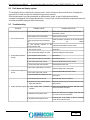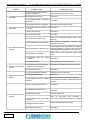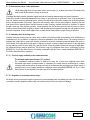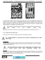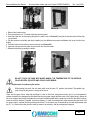
1
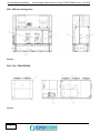
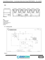
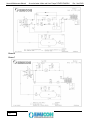
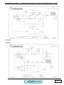
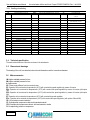
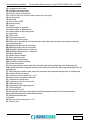
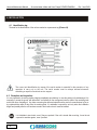
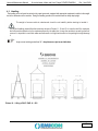
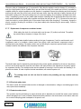
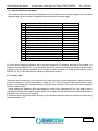
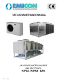
USE AND MAINTENANCE MANUAL
AIR COOLED WATER CHILLERS
AND HEAT PUMPS
R-PAE / R-PAH / EAH
Rev. 1 03/09
Use and Maintenance Manual
Air-cooled water chillers and Heat Pumps R-PAE/R-PAH/EAH Rev. 1 del 03/09
TABLE OF CONTENTS
1. INTRODUCTION ........................................................................................................................... pag. 2
1.1 Manual content ... ....................................................................................................................................
1.2 Safety marks ...........................................................................................................................................
1.3 Referring standards ... .............................................................................................................................
1.4 Warranty ... ..............................................................................................................................................
1.5 Readers of the Manual ... ........................................................................................................................
pag. 2
pag. 2
pag. 2
pag. 2
pag. 3
2. MAIN SAFETY RULES .............................................................................................................. ... pag. 3
2.1 Main warnings ... .....................................................................................................................................
2.2 Allowed use ... .........................................................................................................................................
2.3 Forbidden use ..........................................................................................................................................
2.4 Dangerous areas ... .................................................................................................................................
pag. 3
pag. 3
pag. 3
pag. 4
3. GENERAL DESCRIPTION .......................................................................................................... . pag. 4
3.1 Chillers features and interpreting key ... ...............................................................................................
3.2 Main components ... ................................................................................................................................
3.3 Cooling circuit ... ......................................................................................................................................
3.4 Technical specification ... ........................................................................................................................
3.5 Dimensional drawings ... .........................................................................................................................
3.6 Main accessories ....................................................................................................................................
pag. 4
pag. 5
pag. 7
pag. 14
pag. 14
pag. 14
4. INSTALLATION .......................................................................................................................... .. pag. 16
4.1 Identification tag ... ..................................................................................................................................
4.2 Reception and inspection ... ....................................................................................................................
4.3 Handling ... ..............................................................................................................................................
4.4 Arrangements and placing ......................................................................................................................
4.5 Hydraulic connections ... .........................................................................................................................
4.5.1 Evaporator ... ........................................................................................................................................
4.5.2 Use of anti-freeze mixtures ..................................................................................................................
4.5.3 Hydraulic circuit filling ... .......................................................................................................................
4.6 Electric connections ................................................................................................................................
4.6.1 Power supply connection .....................................................................................................................
4.6.2 Warning in case of connection to the terrmnal board when optional “TE” is installed .........................
4.6.3 Remote control connection ..................................................................................................................
4.6.4 Instructions for the electric connections ... ...........................................................................................
4.6.5 Phases sequence in the power supply line ... .....................................................................................
4.6.6 Application ... ......................................................................................................................................
pag. 16
pag. 16
pag. 17
pag. 20
pag. 24
pag. 25
pag. 26
pag. 26
pag. 27
pag. 27
pag. 28
pag. 29
pag. 30
pag. 31
pag. 31
5. OPERATION ... ............................................................................................................................ .. pag. 32
5.1 First check ... ...........................................................................................................................................
5.2 First startup .............................................................................................................................................
5.3 Microprocessor setting ... ........................................................................................................................
5.4 Fault alarm and display system ..............................................................................................................
5.5 Troubleshooting ......................................................................................................................................
5.6 Routine maintenance ..............................................................................................................................
5.7 Precautionary planned maintenance ......................................................................................................
5.8 Special maintenance ... ...........................................................................................................................
pag. 32
pag. 32
pag. 32
pag. 33
pag. 33
pag. 35
pag. 38
pag. 45
6. DISMANTLING ... ........................................................................................................................ . pag. 46
1
Use and Maintenance Manual
Air-cooled water chillers and Heat Pumps R-PAE/R-PAH/EAH Rev. 1 del 03/09
1. INTRODUCTION
1.1 Manual content
The present handbook, originally written in Italian, was completed in compliance with the “Machinery Directive”. It
contains all the necessary information for carrying out without any risk transportation, installation, startup, operation,
setting, maintenance and dismantling of the air cooled water chillers and heat pumps of series R-PAE / R-PAH / EAH.
Should you have any doubt on the correct understanding of these instructions, please contact the Manufacturer in order to
get further explanations.
1.2 Safety marks
The following safety marks are used in this manual to draw attention to all useful information in order to avoid any dangerous
situation which could be unsafe and harmful for people, could damage equipment and environment besides breaking the unit.
It means operation and behaviour not allowed.
It means danger or risk to people, things or environment.
It means an electrical danger.
It means a warning about important functions or useful information. Pay the maximum attention to the
paragraphs marked with this symbol.
1.3 Referring standards
The units of R-PAE/R-PAH/EAH series are designed and manufactured in compliance with the relevant European
Directives and in particular, they meet the “Essential Safety Requirements” as set out in the European Directive
89/392/CEE, and further amendments, as attested by the CE mark that is on each unit.
As a matter of fact, the units are certified by the manufacturer and are provided together with the CE Declaration of
Conformity which is attached to the present manual.
Where applicable, the units mentioned in this handbook are in conformity with the directive 97/23/CE (PED), concerning the
pressure devices.
1.4 Warranty
The manufacturer warrants the air cooled water chillers and heat pumps according to what stated on his general sales
terms or according to what else explicitly agreed.
The Manufacturer Warranty is void in case the guidance of this manual has not been carefully respected.
The manufacturer refuses all responsibility for any damage to people, animals, things or environment, caused by incorrect
installation, maintenance or setting or misuse of the machine. It is considered as “misuse” of the machine any use not
explicitly allowed in this manual.
2
Use and Maintenance Manual
Air-cooled water chillers and Heat Pumps R-PAE/R-PAH/EAH Rev. 1 del 03/09
Warning: on the first startup, duly fill in the relevant report attached to this manual and
send a copy to Emicon A.C. (Customer Service), in order to make the warranty valid.
1.5 Readers of the Manual
This manual and all its attachments are supplied with the described unit. The manual must be kept by the machine’s
owner in a proper place. To this end, a plastic bag where to store the manual has been placed inside the machine so that
it can be always easily accessible for consultation and at the same time, it can be preserved in a good state.
All people authorized to operate with the unit, in particular, all technicians assigned to the unit maintenance, must
know all information and instructions contained in this manual.
In case the manual is lost or deteriorated, a new copy must be requested directly to the manufacturer.
2. MAIN SAFETY RULES
2.1 General warnings
Read carefully the whole handbook before performing any operation on the unit. Only qualified
and trained technicians must perform any operation on the machine.
Do not touch the machine if with bare feet or with humid or wet parts of the body.
Do not perform any cleaning operation before the main switch is “OFF” and power line disconnected.
Do not spread, leave unattended or to the reach of children any packaging material (carton box,
staples, plastic bags, etc.) as they may be a source of danger.
2.2 Allowed use
RAE - H: packaged air cooled water chillers intended for air-conditioning and/or industrial systems. They are
designed for external installation (units with axial fans) or for internal installation (units with centrifugal fans).
PAE - H : packaged air cooled heat pumps intended for air-conditioning and/or industrial systems. They are
designed for external installation (units with axial fans) or for internal installation (units with centrifugal fans).
2.3 Forbidden use
Do not use the machine:
Ø
Ø
Ø
Ø
Ø
For other use than that described in paragraph 2.2;
When it is exposed to rainfall, especially when the unit is designed for internal installation;
in atmosphere with high risk of fire or explosion;
in spaces with corrosive atmosphere;
to heat or cool aggressive fluids for copper, carbon steel and stainless steel.
Any operation on the unit must be carried out in compliance with local technical standards.
3
Use and Maintenance Manual
Air-cooled water chillers and Heat Pumps R-PAE/R-PAH/EAH Rev. 1 del 03/09
2.4 Dangerous areas
On the unit there are dangerous areas for electric risk and hot temperatures.
The unit can be closed by case panels; in this case the dangerous parts inside the unit are not accessible
from outside. Only qualified and trained personnel can remove the covering panels. The unit is supplied with the
cooling circuit already charged with pressure gas and therefore it is necessary to pay the maximum attention in order
to avoid accidental release of the gas in the atmosphere.
3. GENERAL DESCRIPTION
3.1 Characteristics of the water chillers RAE-H / EAH and of heat pumps PAE-H
The units of series R-PAE / R-PAH / EAH are supplied with refrigerant charge and anti-freeze oil; they are tested
at the factory.
Interpreting key for the initials used to mark the units:
TYPE OF UNIT:
R = water chiller
P = heat pump
E = high efficiency
TYPE OF CONDENSATION: A = air-cooled
TYPE OF COMPRESSOR:
E = hermetic scroll
H = screw
S = semi-hermetic
UNIT COOLING CAPACITY
NUMBER OF INDEPENDENT COOLING CIRCUITS
None= axial (standard)
C = Centrifugal
TYPE OF FANS:
:
FREE - COOLING:
:
None= standard
F = free-cooling
NOISE LEVEL:
:
None= standard
S = Silenced
U = Ultrasilenced
REFRIGERANT GAS:
K = R 407C
Ka = R 134A
Kc = R 410A
None = R22
OPERATION AT EXTERNAL LOW TEMP.
R
4
A
E 160 2 C F U K LT
Use and Maintenance Manual
Air-cooled water chillers and Heat Pumps R-PAE/R-PAH/EAH Rev. 1 del 03/09
3.2 Main components
The units of R-PAE / R-PAH / EAH series are made of the following main components:
Ø The housing is made of galvanized and painted pressure bended steel plate or housing made of aluminium
section;
Ø Compressors, installed on rubber vibration dampers and equipped with oil sump heater,
Ø Weld-brazed plate evaporator or shell & tube evaporator with heat insulation;
Ø Heat exchange coil made of aluminium fins and copper pipes;
Ø Cooling circuit composed of: thermostatic expansion valve, sight glass, dehydrating filter, safety device, anti-freeze
thermostat, high and low pressure switches;
Ø Electric panel in compliance with CE norms and provided with main disconnecting switch; thermal and
amperometric protections, contactors, auxiliary low voltage circuit, terminal board;
Ø The control microprocessor allows to manage the unit operation and its alarms.
RAE - PAE
Picture 1
5
Use and Maintenance Manual
Air-cooled water chillers and Heat Pumps R-PAE/R-PAH/EAH Rev. 1 del 03/09
RAE - PAE with centrifugal fans
Picture 2
RAH – PAH - TWIN VERSION
Picture 3
6
Use and Maintenance Manual
Air-cooled water chillers and Heat Pumps R-PAE/R-PAH/EAH
Rev. 1 del 03/09
RAH
Picture 4
Key
1) Electric panel
2) Compressor
3) Heat exchange coil
4) Evaporator
5) Tank
3.3 Cooling circuit
Picture 5
7
Use and Maintenance Manual
Picture 6
Picture 7
8
Air-cooled water chillers and Heat Pumps R-PAE/R-PAH/EAH
Rev. 1 del 03/09
Use and Maintenance Manual
Air-cooled water chillers and Heat Pumps R-PAE/R-PAH/EAH Rev. 1 del 03/09
Picture 8
Picture 9
9
Use and Maintenance Manual
Picture 10
Picture 11
10
Air-cooled water chillers and Heat Pumps R-PAE/R-PAH/EAH Rev. 1 del 03/09
Use and Maintenance Manual
Air-cooled water chillers and Heat Pumps R-PAE/R-PAH/EAH Rev. 1 del 03/09
Picture 12
Picture 13
11
Use and Maintenance Manual
Picture 14
Picture 15
12
Air-cooled water chillers and Heat Pumps R-PAE/R-PAH/EAH Rev. 1 del 03/09
Use and Maintenance Manual
Air-cooled water chillers and Heat Pumps R-PAE/R-PAH/EAH Rev. 1 del 03/09
Picture 16
Picture 17
13
Use and Maintenance Manual
Air-cooled water chillers and Heat Pumps R-PAE/R-PAH/EAH Rev. 1 del 03/09
3.3.1 Cooling circuits key
AC
AIR HEAT EXCHANGER
PDIO
OIL GAUGE
VE
AD
AIR DISCHARGE VALVE
PDSO
OIL LEVEL PRESSOSTATIC VLAVE
VP
EXPANSION VESSEL
EVAPORATOR
AV
VIBRATION DAMPER
PDSW
DIFFERENTIAL WATER SWITCH
VT
THERMOSTATIC EXPANSION
CM
COMPRESSOR
PIH
HIGH PRESSURE GAUGE
WC
WATER COIL
CO
CONDENSER
PIL
LOW PRESSURE GAUGE
WD
WATER CHARGE AND
CT
CONDUCTIVITY PROBE
PIW
WATER VALVE
WE
WATER EXCHANGER
WATER FILTER
VALVE
DISCHARGE VALVE
EF
FAN
PRV
OVERPRESSURE DISCHARGE DEVICE
WF
EHA
ANTIFREEZE HEATER
PRW
SAFETY WATER FLOW SWITCH
WP
WATER PUMP
EHC
CRANKCASE HEATER
PSH
HIGH PRESSURE SWITCH
WT
WATER BUFFER TANK
EV
SOLENOID VALVE
PSL
LOW PRESSURE SWITCH
BG
HOT GAS COIL
FSR
FAN SPEED REGULATOR
PT
PRESSURE TRANSDUCER
YVCA
HUMIDIFIER FILL VALVE
FWV
4-WAY VALVE
RE
ELECTRIC HEATER
YVSA
HUMIDIFIER DRAIN VALVE
MODULATING VALVE
H
HUMIDIFIER
RV
HR
HEAT RECOVERY
SA
LIQUID SEPARATOR
HT
HUMIDITY PROBE
SFF
FREON –FREON HEAT EXCHANGER
LF
DEHYDRATING FILTER
SFO
FREON –OIL HEAT EXCHANGER
LS
SIGHT GLASS
SL
NOISE LEVEL REDUCER
LT
LIQUID RECEIVER
SO
OIL SEPARATOR
NR
NON-RETURN VALVE
SV
SHUT-OFF VALVE
OF
OIL FILTER
TS
SAFETY THERMOSTATIC VALVE
OLR
OIL LEVEL REGULATOR
TT
TEMPERATURE PROBE
OT
OIL RESERVE
TWV
3-WAY VALVE
3.4 Technical specification
The main technical features of the units are shown in the attachments.
3.5 Dimensional drawings
The drawing of the unit, here attached, shows the unit dimensions and the connections diameter.
3.6 Main accessories
1M: higher available pressure for fans
2M: higher available pressure for fans
A: Amperometer
AE: Power supply different from the nominal power.
BF: Operation at low external air temperatures (-20°C) with constant fan speed regulation by means of inverter
BFa: Operation at low external air temperatures (-20°C) with constant fan speed regulation by means of inverter (with option
1M)
BFb: Operation at low external air temperatures (-20°C) with constant fan speed regulation by means of inverter (with option
2M)
BT: Operation at low external air temperatures (-20°C) with constant fan speed regulation
BTa : Operation at low external air temperatures (-20°C) with constant fan speed regulation ( with options 1M and 2M)
CE: UV protection on water insulation
CF: Soundproofed compressors cabinet with standard material
CFU: Soundproofed compressors cabinet with lead material or similar
CI: Soundproofing jackets on compressors
14
Use and Maintenance Manual
Air-cooled water chillers and Heat Pumps R-PAE/R-PAH/EAH Rev. 1 del 03/09
CS: Compressor inrush counter
DS: Star/Delta compressors startup
FA: Condensing coil protection filters
GP: Protection grid for condensing coil
GP1: Protection grid for the technical section (compressors, pump group)
HG: Hot gas by-pass.
IG: Watch card
IH: Serial interface RS485.
IM: Seawood packing
KS: Lifting kit
I1: Victaulic insulation on pump side
I2: Victaulic insulation on buffer tank side
I3: Victaulic insulation for free-cooling version
LI: Liquid injection
MF: Phase monitor
MP: Oversized microprocessor
MT: High and low pressure gauges
MV: Buffer tank; it is composed of: water tank, expansion vessel, safety valve, hydrometer, water charge and discharge
valve, air discharge valve.
M6: Modulating capacity control for 4-circuit units
M8: Modulating capacity control for 3-circuit units
M12: Modulating capacity control for 2-circuit units
M25: Modulating capacity control for 1-circuit units
OS: Safety oil flow switch
PA: Rubber vibration dampers
PF: Safety water flow switch
PM: Spring-type vibration dampers
PW: Part-winding compressors startup
PQ: Remote microprocessor
P1: Pump group; expansion vessel, safety valve, hydrometer, water charge and discharge valve, air discharge valve.
P1H: Higher head pressure pump group; expansion vessel, safety valve, hydrometer, water charge and discharge valve, air
discharge valve.
PT: Twin-pump group; expansion vessel, safety valve, hydrometer, water charge and discharge valve, air discharge valve.
RA: Antifreeze heater on evaporator.
RF: Power factor correction system cos = 0,9
RH: Shut-off valve on compressor suction side
RL: Compressors overload relays.
RM: Condensing coil with fins in marine alloy
RP: Partial heat recovery
RR: Condensing coil with copper/copper fins
RT: Total heat recovery.
RV: Personalised RAL paint
SC: Soundproofed compressors housing with standard material (already included in the Ultra-silenced versions)
SU Soundproofed compressors housing with lead material
TE: Electronic thermostatic valve
V: Voltmeter.
VB: Brine version (water temperature < 0°C)
VS: Solenoid valve.
15
Use and Maintenance Manual
Air-cooled water chillers and Heat Pumps R-PAE/R-PAH/EAH
Rev. 1 del 03/09
4. INSTALLATION
4.1 Identification tag
The data for the identification of the unit are marked on a permanent tag (Picture 18).
Picture 18 – Identification tag
The correct unit identification by means of the serial number is essential for the execution of any
operation to carry out on the unit. The serial number must be always advised whenever
submitting a request of technical service support.
4.2 Reception and inspection
It is very important to check the packing integrity immediately upon delivery. In case the packing is found damaged, it is
necessary to accept the goods “with reservation” and indicate on the consignment note the state of the received goods
and let the driver countersign it. Any claim concerning the delivered material must be sent to the manufacturer by fax or
by registered letter within 8 days from the receiving date. It is advisable to unpack the unit only when the installation
begins and possibly after the unit has been moved to the location where it must be installed.
It is forbidden to stack units, even if they are packed. If the unit is stored after receiving, it must be not
exposed to weather agents, even if packed.
16
Use and Maintenance Manual
Air-cooled water chillers and Heat Pumps R-PAE/R-PAH/EAH
Rev. 1 del 03/09
4.3 Handling
The handling of the unit must be carried out by expert personnel, equipped with appropriate equipment in relation to the weight
and to the dimensions of the machine. During the handling operation, the machine must be always kept upright.
The weight of some models is unbalanced: check the unit stability before starting to handle it.
For any unit handling, please follow the instructions shown in Pictures 11, 12 and 13. In case the fork lift is employed,
the forks must be spaced out to the maximum allowed by the pallet size. In case the machine is moved by means of
a crane, it is important to avoid that cables and belts exert a too high tractive effort on the packing that might damage
it.
Angle must not be greater than 30°; the pictures are just as an indication.
Picture 19 – Lifting of RAE / PAE 41 - 822
17
Use and Maintenance Manual
Air-cooled water chillers and Heat Pumps R-PAE/R-PAH/EAH
Picture 20 – Lifting of centrifugal units
Picture 21 – Lifting of RAE / PAE 752 - 3172
18
Rev. 1 del 03/09
Use and Maintenance Manual
Air-cooled water chillers and Heat Pumps R-PAE/R-PAH/EAH
Rev. 1 del 03/09
Picture 22 – Lifting of RAH / PAH TWIN 2102 - 8802
Picture 23 – Lifting of RAH / EAH 301 - 2214
19
Use and Maintenance Manual
Air-cooled water chillers and Heat Pumps R-PAE/R-PAH/EAH
Rev. 1 del 03/09
In case the manufacturer lifting kit (option) is not employed, make sure that the lifting
equipment used, the cables and the belts are in compliance with the relevant local regulation.
The overall dimensions of the units, packaging included, are indicated in the packing list sent by e-mail in order to
organise the loading.
4.4 Arrangements and placing
The installation of the machine is under the responsibility of the installer who must supervise the execution operations.
The execution of a correct installation presupposes that a plan has been drawn up by an expert and that is
carried out by skilled and trained technicians.
In the following paragraphs there are some tips and information to keep in mind when planning and
executing the machine installation.
The unit installation must comply with local existing laws.
Before placing the unit, the following points must be checked:
Ø Connections for electric and hydraulic circuits must be done;
Ø Enough room must be left around the unit to allow the routine and the special maintenance, such as
compressors and heat exchangers replacement. The dimensions of this free space is represented by the
dashed area as shown in Pictures from 24 to 31, for units with single and multi-scroll compressors and for units
with screw compressors.
Ø The floor where the machine is positioned can bear the total unit weight under normal operation.
Picture 24 – Service Area for RAE / PAE 41 - 101
20
Use and Maintenance Manual
Air-cooled water chillers and Heat Pumps R-PAE/R-PAH/EAH
Picture 25 – Service Area for RAE / PAE 131 - 822
Rev. 1 del 03/09
RAE / PAE version C 131 - 181
Picture 26 – Service Area RAE / PAE 752 - 3172
21
Use and Maintenance Manual
Air-cooled water chillers and Heat Pumps R-PAE/R-PAH/EAH
Picture 27 – Service Area for RAH / PAH TWIN 2102 - 8802
Picture 28 – Service Area for RAH / EAH 301 - 2214
22
Rev. 1 del 03/09
Use and Maintenance Manual
Air-cooled water chillers and Heat Pumps R-PAE/R-PAH/EAH
Rev. 1 del 03/09
Picture 29 – Service Area for RAE / PAE version C 201 - 822
Picture 30 – Service Area for RAE / PAE 842 - 2602 version C
23
Use and Maintenance Manual
Air-cooled water chillers and Heat Pumps R-PAE/R-PAH/EAH
Rev. 1 del 03/09
Picture 31 – Distances in case of coverings
Before starting to handle the unit to position it, it is necessary to identify the best way to arrive to the place,
taking into consideration the unit overall dimensions and weight, the available lifting equipment and any
optional accessory dimensions. All units described in this manual do not need any special foundation, since
they can be simply laid down on the chosen surface, just placing rubber gaskets or spring-type vibration dampers
(options) underneath. Make sure that the unit features indicated in the attached technical data sheets match those
required for the undertaken project.
4.5 Hydraulic connections
The units are designed to be connected to a distribution system of cooled and/or heated water depending on the
type of unit, if it is a water chiller or a heat pump. Only expert refrigeration technicians are allowed to perform the
hydraulic connections and in conformity with local regulations. The following general instructions must be
followed:
Perform the piping path in such a way so as to limit as much as possible the pressure drop in the system.
The water circulating pump must be able to deliver the appropriate water flow capacity with the
necessary available pressure to overcome the system pressure drop in any operating conditions.
Pipes must be adequately supported by brackets and arranged so as to allow an easy installation
and inspection.
The materials used for the realisation of the system must have a nominal pressure not lower than PN6.
During the piping insallation, all necessary measures to prevent dirt and solid particles from entering the
tubes must be taken.
Once the pipes are placed and the unit installed, the system must be leak tested to detect any
possible leak to be repaired before the starting up of the system.
Ø
Ø
Ø
Ø
Ø
Ø
Do not exceed 6 bar during the leak test!
24
Use and Maintenance Manual
Air-cooled water chillers and Heat Pumps R-PAE/R-PAH/EAH
Rev. 1 del 03/09
Ø The unit must be connected to the hydraulic system by using the appropriate areas as indicated in the
commercial drawing here attached.
Ø The diameter of the hydraulic connections are shown in the commercial drawing here attached.
For the connections dimension, see the commercial drawing here attached.
4.5.1 Evaporator
For the connection of pipes to the evaporator, it is advisable to follow the instructions listed here below:
Ø Connect the pipes as shown in the diagram in Picture 32;
Ø Employ anti-vibration pipe fittings to avoid any vibration transmission and to allow the thermal expansion;
Ø Install on the water inlet a filter with grid not larger than 1 mm and with a bigger diameter than the pipe
diameter;
Ø Place the air discharge valves in the appropriate points of the hydraulic system;
Ø Install a ball check valve on the inlet and outlet so that it is possible to shut off the unit in case of special
maintenance operations. The installation of three-piece joints between the valves and the chiller will ease
these operations;
Ø The water system pressure must range between 1,5 and 3,5 bar.
Ø In case of low evaporating temperatures (< 4°C) it is recommended to employ anti-freeze mixtures
(glycol) as shown in the following tables, according to the kind of glycol used:
Picture 32 - Piping connection diagram
If the unit is not equipped with a water pressure switch (optional), it is recommended to install a
safety flow switch on the hydraulic system so that the unit can be shut off in case the water flow to
the exchanger is insufficient. This device must be connected to the relevant terminals inside the
electric panel (see the attached wiring diagram).
If the anti-freeze mixture contains a lower ethylene glycol percentage than below recommended, there could be risks of
freezing, while a higher percentage can reduce the unit performance. At the beginning of every winter, it is recommended to
check the correct concentration of glycol in the system.
Do not use anti-freeze liquids unsuited to copper, stainless steel and to all other materials present in the system.
The cooled water system must be heat insulated with closed-cells material having adequate features
of heat insulation and steam resistance for the unit operating conditions.
Description
Freezing
temperature
5%
Ethylene glycol percentage on the mixture weight
10%
15%
20%
25%
30%
35%
40%
-2,1
-4,5
-25
-7
-10
-13
-17
-21
25
Use and Maintenance Manual
Air-cooled water chillers and Heat Pumps R-PAE/R-PAH/EAH
Rev. 1 del 03/09
Use of anti-freeze mixtures
In case an anti-freeze mixture is used, it is necessary to follow some precautionary measures:
Ø
The temperatures shown in the above table are approximate. Sometimes suppliers dilute the product and
therefore it is necessary to follow the dilution percentage recommended by the anti-freeze liquid
manufacturer.
Ø
Do not release the anti-freeze solution in the environment, but deliver it to an authorized waste disposal
facility.
Ø
Make sure the anti-freeze fluid used is compatible with the system materials.
Ø
If we increase the anti-freeze quantity we get a higher anti-freeze protection, but as a consequence the
solution will become denser (and more viscose when cold), thus overloading uselessly the circulating pump
and thus reducing the unit performance.
Ø
Do not use anti-freeze substances such as chloride or other products that might cause electrogalvanic
corrosion.
Ø
Change the anti-freeze solution every two years.
4.5.2
The inhibited monoethylene glycol is harmful if ingested and can cause irritation if on contact
with skin and sensitive mucous membranes. Therefore, it is recommended to wear protection
glasses and gauntlets and to avoid the contact with the mouth; follow the safety instructions
indicated on the container or in the corresponding directions.
4.5.3
Hydraulic circuit filling
Once the hydraulic circuit and the unit connection are performed, it is necessary to fill the circuit.
Ø
Open all the air discharge valves on the circuit.
Ø
Connect the circuit to a water supply system, possibly in a permanent way, by means of an automatic fill group
provided with a manometer and a non-return valve.
If the circuit works with an anti-freeze mixture, fill the circuit with an appropriate quantity of pure antifreeze fluid according to the system size and to the anti-freeze concentration to get.
Ø
Ø
Ø
Start filling the system with water;
Check all the air discharge valves present on the system and shut them when water, instead of air, starts to go out.
Once all valves are closed, go on filling the system with water until a pressure between 1,5 and 3,5 bar is reached.
In case filling is done manually, stop the water charge and start the circulating pumps so that any presence of air can
be gathered in the top points where air discharge valves are present. After two operating hours, stop the pumps and
discharge the air by means of the air discharge valves. Charge more water to bring pressure back to its orginal
value. Repeat the operation until no air goes out from the air discharge valves.
Make sure the water pressure in the system always ranges between 1,5 and 3,5 bar.
After the leak test with water is performed, if low ambient temperatures or a long break before the
startup are likely, it is recommended to drain the circuit or to fill it with an anti-freeze mixture. The
draining must be particularly accurate in case free-cooling coils are installed.
26
Use and Maintenance Manual
Air-cooled water chillers and Heat Pumps R-PAE/R-PAH/EAH
Rev. 1 del 03/09
4.6 Electric connections
Check the electric circuits have not been damaged during transportation. Check all terminals screws are tight. Make sure
the power tension and frequency match the same data as specified on the unit identification tag.
Before starting the electric connection, it is advisable to check the wiring diagram contained in the unit
electric panel.
4.6.1 Power supply connection
The unit can be powered with a 5-pole cable (3 poles+N+ T), if the power supply tension is 400V/3F/50Hz. In case the
power supply tension is 230V/3F/50Hz, the supply cable is a 3-pole cable. On demand, it is possible to supply units
with arrangements for special power supply tension (check the identification tag and the wiring diagram).
Connect the phases and the neutral to the terminals of the main switch and the earth wire to its corresponding
terminal. Use a power supply cable of adequate cross section and of moderate length to avoid voltage drops.
Protect the power supply cable by means of an automatic switch of appropriate size and features.
For the cross section of the power supply cable, the size of the automatic switch and the
characteristics of the electric components, check the wiring diagram attached to the present
manual.
27
Use and Maintenance Manual
Air-cooled water chillers and Heat Pumps R-PAE/R-PAH/EAH Rev. 1 del 03/09
4.6.2 Warning in case of connection to the terminal board when optional “ TE” is installed
In case the unit is provided with optional TE (electronic thermostatic valve), pay the maximum attention to the spare
battery power supply.
“GB1” (spare battery) is an electronic device which guarantees a temporary power supply to the “Driver” device in case of
sudden power supply shortage, thus allowing the immediate shutoff of the thermostatic valve.
Before perfoming any operation, it is advisable to check the charge of the battery as per the instructions;
Ø Power the control
Ø Press the button I/O
Ø Check parameter N4
For further information, check the control manual on chapter 7, section “input-output/driver” and chapter 9. If battery
is flat, 48 hours are needed to charge it.
During the check-up operation before the unit startup, it is advisable to disconnect the spare battery to avoid that
continuous power and disconnection operations might damage it.
- open the duct above the component GB1 (driver battery EVV) and disconnect the power supply cables (see the
picture)
Picture 33
Once the test is completed, it is reminded to re-connect the battery to
bring the unit back to a safety condition.
28
Use and Maintenance Manual
Air-cooled water chillers and Heat Pumps R-PAE/R-PAH/EAH
Rev. 1 del 03/09
4.6.3 User’s terminal board connection
A user terminal board (Picture 35) is available with free contacts designed for:
Ø
Generic alarm state (1);
Ø
Unit remote ON/OFF (2).
Check the wiring diagram for the exact correspondence of the terminals numbers.
L1
L2
L3
N
Picture 34
2
1
U2: open contact
UNIT OFF
30: closed contact
UNIT ON
U9: usually open
U10: common
U11: usually closed
Picture 35
29
Use and Maintenance Manual
Air-cooled water chillers and Heat Pumps R-PAE/R-PAH/EAH
Rev. 1 del 03/09
4.6.4 Instructions for the electric connection
The electric connection must be carried out by skilled personnel. The power cable input is shown in the attached
dimensional scheme.
Picture 36
The power cable conductors must be connected to the free terminals upstream the main disconnecting switch, while
the grounding conductor must be connected to the appropriate terminal PE or to the ground bar.
On the lateral side of the unit, a hole must be performed to introduce the electric power cable and to arrange its
corresponding cable connection.
Picture 37
Picture 38
If the power cable comes from the top wiring box, perform a bend on the cable (Picture 38)
before plugging it into the cable connection as illustrated in the example on the top on the right.
If the water circulating pump is not controlled by the unit microprocessor, it is recommended to connect an auxiliary
contact of the pump electromagnetic switch to the remote ON/OFF terminals preset in the electrical panel (see
attached wiring diagram), so that the unit can start only when the pump is working.
On its cover, the electrical board has the programming panel of the unit microprocessor. For the controls
management, its functions and for the microprocessor use, see Chapter 8 “Unit control and start-up” of the present
manual.
30
Use and Maintenance Manual
Air-cooled water chillers and Heat Pumps R-PAE/R-PAH/EAH
Rev. 1 del 03/09
Picture 39
4.6.5
Phases sequence in the power supply line
The rotation direction of all electric motors installed on the unit (compressors, fans, pumps) are checked and
harmonized during the operational test performed by the manufacturer (at the exception of units supplied with
arrangements for special power supply tension). In case of three-phase power supply, when connecting the unit to
the power supply, it is necessary to check that the phases are connected in the correct sequence. On this purpose,
make sure that all electric motors rotation is right: for pumps and fans, refer to the information indicated on the
component itself; for scroll compressors, follow the instructions as described at Par. 5.1.
If the rotation of any component is wrong, two out of three phases must be inverted in the terminals of the main
switch (do not unplug the neutral). If some components go on rotating in the wrong direction, check the conductors
sequence of each 3-phase component and correct it, if needed.
4.6.6 Application
The nominal water flow capacity refers to a temperature difference of 5°C between the inlet and outlet depending on
the supplied cooling capacity. The maximum allowed capacity is equal to 1,2 times the above mentioned value
(higher flow rates could cause noise and vibrations with consequent damage to the evaporator).
The minimum allowed flow capacity is equal to 0,8 times the nominal value (lower flow rates might cause a too low
outet water temperature thus involving the safety device activation and the unit stop).
Unit
Water chiller
WORKING LIMITS
Water temperature
min evaporator outlet H2O Temp = 5° C(4)
max evaporator inlet H2O Temp = 20° C
Heat pump
min condenser inlet H2O Temp = 25° C(2)
max condenser outlet H2O Temp = 50° C(3)
Air temperature
ext. Air Temp: varies between +15 and
+40° C(1)
There are no special limits, but the
operation with low T° (below 0°)
reduces
significantly
the
unit
performance.
tab. 10
(1) for different applications, contact the Customer Service
(2) lower temperatures can cause unit malfunctioning
(3) higher temperatures can enable the safety device and stop the unit
(4) if the unit works with water temperatures lower than 5°C (on the evaporator outlet), besides using a water/ethylene
glycol mixture, it is necessary to reset the anti-freeze thermostat (always 4° C above the mixture freezing point) and the
set-point according to the desired temperature and to the temperature difference to the evaporator.
31
Use and Maintenance Manual
Air-cooled water chillers and Heat Pumps R-PAE/R-PAH/EAH Rev. 1 del 03/09
5. OPERATION
5.1 First check
Before starting the unit, make sure that:
Ø
The evaporator water side is supplied with a suitable water flow according to the project;
Ø
The hydraulic connections are carried out following the use and maintenance manual;
Ø
The hydraulic circuit is charged and air free;
Ø
The shut-off valves on the hydraulic circuit are open;
Ø
All security conditions are respected;
Ø
The unit is placed correctly on the floor;
Ø
The service area is respected;
Ø
The electric connections are performed correctly;
Ø
The electric tension ranges within a tolerance of 10% compared to the unit nominal tension;
Ø
The connection to ground is performed correctly;
Ø
All electric and hydraulic connections are tight properly.
If a 3-phase scroll compressor is installed on the unit, when starting, check the rotation is correct. If the compressor
rotates in the opposite direction, it produces a higher noise level, it causes a pressure difference between
discharge and suction and its electric absorption is lower than scheduled; after few minutes of operation with the
reversed rotation, the internal heat protection can be enabled. If necessary, reset the correct rotation direction by
inverting two out of three phases in the input terminals of the main switch.
5.2 First startup
The first startup must be performed by a skilled refrigeration technician. The oil heaters must be energized for at
least 3 hours before the unit startup, and for 6 hours in case of screw compressors. Check the shut-off valves on
compressor and on the cooling circuit are open. Make sure all points described in the previous paragraph have
been checked.
To start the unit:
Ø
Turn the main switch to “ON” position.
Ø
Press the ON/OFF button on the microprocessor keyboard.
Compressors startup time-delay has a default value equal to 1 minute and it can be re-set. Check
all safety and control devices are working properly.
To stop the unit:
Ø
Press the ON/OFF button on the microprocessor keyboard;
Ø
If the unit must not work for more than 24 hours, turn the main switch to OFF position.
5.3 Microprocessor setting
Make sure the desired parameters are set on the microprocessor.
If the preset parameters need to be changed, proceed as described in the microprocessor manual (here
attached).
The standard units are designed to work with an outlet cooled water temperature higher than 5°C; for
operation at lower temperatures, use anti-freezing solutions having adequate properties. If necessary,
set the anti-freeze set point.
32
Use and Maintenance Manual
Air-cooled water chillers and Heat Pumps R-PAE/R-PAH/EAH Rev. 1 del 03/09
5.4 Fault alarm and display system
The troubleshooting is realized by the microprocessor, which activates an alarm and shows on its display the
type of fault occurred (see also the attached microprocessor manual).
Since the alarm state is very often generated by an unfitted electric contact, in case of fault make sure all wiring
connections are plugged in the corresponding terminals. In case of fault, consult the attached microprocessor manual to
check the parameters setting has been done properly.
5.5 Troubleshooting
TROUBLE
1. The unit does not work
POSSIBLE CAUSE
CORRECTIVE ACTION
A) The electric panel is not powered.
Check presence of electric tension; make sure the
main switch is closed.
B) The auxiliary circuit is not powered.
Check fuses FUT and FUA
Check the electric connections to the microprocessor
and
the
setpoint
C) The microprocessor does not start the
unit
D) The external impulse to the
Check the remote ON/OFF contact is closed
microprocessor fails
A) The unit does not work
See trouble 1
B) The control system setting is not correct
2. Cooled water temperature
too high
Check the setting of the control system
C) The compressor does not work
See trouble 11
D) The compressor output is not sufficient
See troubles 7 and 10
E) The control system does not work
Check the attached Microprocessor manual
F) Thermal load higher than estimated
Check the thermal load value
A) The control system setting is not correct
Check the setting of the control system
3. Cooled water temperature
too low
B) The control system does not work
C) The cooled water flow capacity is too low
Check the attached Microprocessor manual
See trouble 4
A) The water pump does not work
Check the pump electric connections
B) Pressure drop in the hydraulic system
higher than estimated
Check the pressure drop and compare it with the pump
head pressure
4. Cooled water flow capacity C)
The pump
activated
heat
protection
is
Check pump winding electric resistance; after reset, check
tension and electric absorption
D) Obstruction in the hydraulic circuit
Make sure filters are not clogged; check the shutoff valves on the circuit are open.
E) Air presence in the hydraulic circuit
Discharge the air by means of the air discharge
valves on the hydraulic circuit
33
Use and Maintenance Manual
TROUBLE
Air-cooled water chillers and Heat Pumps R-PAE/R-PAH/EAH Rev. 1 del 03/09
POSSIBLE CAUSE
A) The high pressure switch is not set
properly or is defective
CORRECTIVE ACTION
Replace the high pressure switch or reset it
5. The high pressure switch
B) Discharge pressure too high
See trouble 7
is activated
C) The condensing water flow capacity is
See trouble 4
not sufficient
A) The low pressure switch is not set properly
Replace the low pressure switch or reset it
6. The low pressure switch B) The cooled water flow capacity is not
See trouble 4
is activated
sufficient
C) Suction pressure too low
See trouble 10
A) Suction pressure too high
See trouble 9
B) The finned heat exchanger is dirty
Remove the obstructing material (leaves, paper,
seeds, etc.)
C) Circuit charged with too much refrigerant
High refrigerant undercooling:
refrigerant from the circuit
7. High compressor discharge
D) Non-condensable air or gas in the circuit
pressure
E) Too hot water at the condenser
discharge
some
The flow sight glass shows gas bubbles. The compressor
discharge temperature is high; the cooling circuit must
be discharged and recharged after the vacuum execution.
Check capacity of the condensation water cooling
system
F) Condensing water flow capacity
See trouble 4
insufficient
8. Low compressor discharge
pressure
9. High compressor suction
pressure
G) Encrusted condenser
Wash the exchanger with suitable products
A) The control system of the condensation
pressure is not working properly
Check setting and operation of the thermostatic valve
B) Suction pressure too low
See trouble 10
A) Thermal load higher than estimated
Check the room thermal load value
B) Discharge pressure too high
See trouble 7
Make sure the thermostatic valve overheating is
C) Liquid refrigerant return to the compressor
correct; check the valve bulb is properly placed, fixed and
suction side
insulated.
A) Cooled water temperature too low
B) Cooled water flow capacity too low
10. Low compressor suction
pressure
C) Clogged refrigerant filter
D) The thermostatic valve is not set properly
or is defective
E) Refrigerant charge is insufficient
F) Discharge pressure too low
34
See trouble 3
See trouble 4
Check the refrigerant filter
Check the thermostatic valve overheating is
correct; check the thermostatic element is not damaged
Check possible leakage and recharge
See trouble 8
Use and Maintenance Manual
TROUBLE
Air-cooled water chillers and Heat Pumps R-PAE/R-PAH/EAH Rev. 1 del 03/09
POSSIBLE CAUSE
A) Automatic switch activated
CORRECTIVE ACTION
Reset the automatic switch; check the cause
for the activation
Check the compressor winding resistance; after
11. The compressor does
B) Compressor internal heat protection reset, check the tension and the electric absorption;
not
work
check the working parameters are in the nominal
activated
range of values
12. The compressor is noisy
13. Probe alarm
C) The contactor does not work
Check the contacts and the contactor coil
A) Liquid return to the compressor
Check the thermostatic valve overheating is correct;
check the valve bulb is properly placed, fixed and
insulated
B) The compressor is damaged
Replace the compressor
A) The probe corresponding to the alarm Check the probe connection and if it works; in case of
code is defective or disconnected
defect, replace it.
5.6 Routine maintenance
5.6.1 Type and frequency of periodical checks
Before acceding any component inside the unit, turn the main switch of the power supply to OFF position.
Then, also turn the unit main switch to OFF position.
Only trained technicians are alllowed to perform operations with powered electrical panel and with
open panel board, since some functions of the system fail.
It is recommended to carry out periodical checks in order to make sure the unit works properly. Only authorized and
skilled technicians are allowed to perform this kind of operations, included any maintenance operation.
5.6.2 Operations on the cooling circuit
Every time an operation involves the cooling circuit discharge, the gas must be collected by means of the appropriate
gas recovery for environmental safety reasons.
Once the repair on the cooling circuit is performed, carry out the following operations:
Ø Leak detection;
Ø Vacuum and dehydratation;
Ø Refrigerant charge.
A) LEAK DETECTION
Charge the cooling circuit with the gasous refrigerant up to reach a pressure of 1 bar. Then, add anhydrous nitrogen by
means of cylinders with reducer up to reach a pressure of 15 bar.
Look for possible leakage and, if present, discharge the cooling circuit before welding (with phosphorus copper
alloy with a minimum of 2% of silver).
Discharge completely the cooling circuit before welding in order to avoid explosions.
Do not use oxigen instead of nitrogen in order to avoid explosions.
35
Use and Maintenance Manual
Air-cooled water chillers and Heat Pumps R-PAE/R-PAH/EAH
Rev. 1 del 03/09
B) VACUUM AND DEHYDRATATION
To obtain a good level of vacuum, an appropriate pump must be used (1,4 mbar of absolute pressure, 30 l/min.
of water capacity). If the circuit has been open only for short time, by using this pump, only one vacuum
operation is usually enough to reach the absolute pressure 1,4 mbar. If such a vacuum pump is not available or if
the circuit has been open for long time, it is highly recommended to perform the vacuum three times by breaking the
vacuum by means of the refrigerant. This method is also suitable when there is a high quantity of moisture in the
circuit. The vacuum pump must be connected to the charge connections on high and low pressure side of the circuit.
Follow this procedure:
Ø Discharge the circuit up to an absolute pressure of 35 mbar, then charge the cooling circuit with
refrigerant gas up to reach a pressure of about 1 bar;
Ø Repeat again the operation as described above reaching an absolute pressure of 35 mbar;
Ø Repeat the above operation for the third time reaching the minimum absolute pressure as possible.
This operation allows to remove up to 99% of the polluting substances.
C) REFRIGERANT CHARGE
Follow this procedure:
Ø Connect the refrigerant gas cylinder to the male charge connection 1/4” SAE placed on the liquid line,
letting some gas go out to remove the air in the connection pipe;
Ø Turn the cylinder upside down and charge the liquid up to reach 75% of the total charge;
Ø Now connect to the charge connection on the suction line and, keeping the cylinder upright, complete
the charge till the temperature of the liquid pipe before the filter is lower than 7-8°C for the chiller (4°C
for the heat pump) compared to the temperature shown on the refrigerant manometer for the discharge
pipe.
36
Use and Maintenance Manual
Air-cooled water chillers and Heat Pumps R-PAE/R-PAH/EAH Rev. 1 del 03/09
5.6.3 Check of the setting up
The setting up must be checked while the unit is working in conditions as close as possible to the nominal ones.
Make sure:
Ø The thermal load is adequate;
Ø The water capacity and the evaporating and condensing water temperatures are close to the nominal ones.
Check the gas charge: the charge will be complete when, after 10 minutes of operation in nominal conditions, no
bubbles are shown in the liquid sight glass.
Check the gas overheating on the compressor intake as shown below and, if necessary, set the thermostatic valve.
While the unit is working in nominal conditions, connect a manometer on the low pressure side. Check the gas
temperatature on the compressor intake (Picture 41) by means of a thermometer (Picture 40).
The overheating intake value is given by the difference between the temperature shown on the thermometer and the
saturation temperature (dew value for mixture) corresponding to the pressure shown on the manometer. If
overheating is higher than 10°C, the thermostatic valve must be opened, while if it is lower than 5°C the valve
must be shut off (Picture 42 cap removal and Picture 43 opening adjustment).
Valve adjusting operations must be always carried out with caution, turning the adjusting screw only half turn
each time; wait for few minutes before every new adjustment in order to allow the unit to reach steady conditions.
Gas: R407C
Intake
Temp.
7°C
Suction
pressure:
3,9 bar = +2°C
Overheating: 5K
Picture 40
Picture 42
Picture 41
Picture 43
The thermostatic valve adjustment is a very delicate operation, therefore it must be carried out by a skilled
technician.
37
Use and Maintenance Manual
Air-cooled water chillers and Heat Pumps R-PAE/R-PAH/EAH
5.7 Precautionary planned maintenance
List of operations
Every 6 months
Check of cooling lines and of their insulation
x
Compressor noise level check
x
Electric connection tightening check
x
Contactors status check
x
Check of conductors insulation status
x
Check of evaporator water temperature difference
x
Liquid sight glass check
x
Electric absorption check
x
Working pressures check
x
Unit general conditions check
Probes setting check
Every year
x
x
Set parameters check
x
Refrigerant filter pressure drop check
x
Safety valve check
x
Safety pressure switch check
x
Electric protections check
x
Thermostatic valve check
x
Check of air presence in the hydraulic circuit
x
Check of condenser water temperature difference
x
Check of condenser cleaning condition
38
x
Rev. 1 del 03/09
Use and Maintenance Manual
Air-cooled water chillers and Heat Pumps R-PAE/R-PAH/EAH
Rev. 1 del 03/09
5.7.1 Coils cleaning (on the floor and under coverings)
Use a stiff-bristle brush and the necessary equipment; the use of an industrial vacuum cleaner may facilitate this
operation.
a. Disconnect the unit from the power supply by opening the main switch,
b. Remove the protection grid from the coil (if present),
c. Brush the coil from the top to the bottom, being careful not to damage the fins.
d. Accompany the brushing with the hoovering.
e. Remove the dust and the down gathered.
Do not use compressed air (it might damage the fins) or water (it might cause scale).
5.7.2 Check of the hydraulic circuit and expansion vessel pressure
The hydraulic circuit pressure is determined by an expansion vessel and it is signalled outside the unit through a
manometer. The pressure shown on the manometer must range between 0,15 and 0,30 MPa (1,5 and 3,0 bar).
If the circulating pump and/or the tank are installed on the unit, then the manometer and the
expansion vessel equipped with a water fill valve (visible in the picture below the manometer) are
also provided with the unit; on the contrary, it is the customer who must take care about their
installation.
5.7.3 Check of lubricant leaks – lubrication oil pressure
A lubricant oil leak in a cooling circuit is always accompanied by a refrigerant leak, therefore this check allows to detect
possible leaks in advance. The inspection is visual-type and it is sufficient to light the areas to be checked by means of
a good electric torch. All piping fittings and joints (welded and not welded) must be checked since they are more
subject to vibration; if some oil is detected, contact the closest After Sale Centre for intervention. The lubrication oil
pressure must be checked through the appropriate manometer (when present); the oil pressure must always be at
least 0,15 MPa (1,5 bar) higher than the value shown on the low pressure gauge (L.P.).
5.7.4 Vibrations check
The cooling circuit is composed of several rotating parts (fans, compressors, pumps, etc) equipped with bearings and
they are balanced at the beginning; excessive vibrations, scrapings, strikings, irregular noises such as whistles and
creakings are all signals of mechanical troubles which might even generate serious and dangerous damages. The
inspection must be performed while the unit is working and with the protection covers closed; in case of trouble,
contact the closest technical service centre.
5.7.5 Check of terminals tightening
The vibrations the unit housing is subject to (and the electric box by transmission) can loosen the electric terminals
thus causing malfunctionings; therefore, open the unit main switch and tighten all terminals screws; eventually, if it is
always the same terminals to be loosened, contact the After Sales Service of EMICON A.C. S.p.A to report the fact.
5.7.6 Check of the safety water flow switch
The safety water flow switch detects the water pressure difference between the exchanger inlet and outlet. If the tube
marked by the white arrow is clogged by dirt or air (or is bended rudely and it chokes), the safety water flow switch
might stop detecting the pressure change and the system stops. Check the tube condition, make sure it is cleaned, the
piping fittings do not leak and discharge any air, if present.
39
Use and Maintenance Manual
Air-cooled water chillers and Heat Pumps R-PAE/R-PAH/EAH
Rev. 1 del 03/09
Picture 44
5.7.7 Check of the gaskets on the centrifugal fans discharge
The centrifugal fans discharge is connected to the external skirt by means of a flexible gasket; the gasket must not be
damaged and must not let air pass through. In this case, its replacement is necessary, therefore contact EMICON A.C.
S. p. A. After Sales Service.
5.7.8
Compressors oil level check
Both scroll and semi-hermetic compressors are equipped with sigth glasses to check the oil level.
WHILE CHECKING THE OIL LEVEL ALWAYS MAKE SURE THE FAN SECTION IS NOT OPEN
Oil level must be checked while the unit is working in steady conditions (therefore, after at least 15-20 minutes of
operation). The oil level must be compared with the instructions shown on tags close to the sight glass; however,
at least a quarter on the bottom of the sight glass must show the oil. An excessive presence of foam means that
the thermostatic valves are not set up properly.
In case of trouble, contact EMICON A.C. S.P.A. After Sales Service.
5.7.9 Insulation condition check
All low temperature parts are heat insulated by means of muffs or of shaped plates to eliminate or reduce any
heat leak which can cause a cooling capacity reduction as well as condensing phenomena or ice formation (which
can be dangerous since in some conditions they can cause mechanical breakings). The check is of visual type;
the insulation must not be damaged, detached from the supports or cracked. Bear in mind that in time the surface
of insulating materials tends to slightly flake off without jeopardizing the insulation feature. Cracks, cuts or
detachments must be repaired immediately by sticking or taping properly.
5.7.10 Supports and bearings check
While making the check, the unit main switch must be open (“0” position) and locked. The padlock
key must be kept by the person in charge of the check.
All rotating parts are equipped with supports and bearings. Usually these parts do not need any maintenance and/or
lubrication as they are a long-life type. A direct check of these parts is only possible on fans by rotating manually the
fan wheel: its movement must be fluid, with no blockings or creakings and it must not show any lubricant leak. If any of
the mentioned cases occurs, contact EMICON A.C. S.p.A. After Sales Service for repairing it.
40
Use and Maintenance Manual
Air-cooled water chillers and Heat Pumps R-PAE/R-PAH/EAH
Rev. 1 del 03/09
5.7.11 Belts tension check – belts replacement
While making the check, the unit main switch must be open (“0” position) and locked. The padlock key
must be kept by the person in charge of the check.
Centrifugal fans belts must be checked at regular intervals and must be replaced every two years of operation.
Press firmly the belt in the middle between the two pulleys: it must give way no more than 5 mm; if it gives way more
than that, unblock the motor tightening screws, unscrew the belt-tensioner bolt after screwing the other belt tensioner
bolt on the opposite side of the motor. Tighten the belt correctly, make sure the pulley engine is aligned to the duct
(use the bolt on the opposite side of the belt tensioner to make it easier), overflow the motor on the base. To replace
the belt, loosen the motor tightening screws, screw completely the belt tensioner bolt and close the motor to the fan
housing, remove the belt from the pulleys, replace it with another belt having same form and size and tighten as above
mentioned explained. In case of belt replacement, re-check the belt tension after a couple of days of operation.
5.7.12 Humidity check of cooling circuit
Humidity inside the cooling circuit can cause many troubles (ice formation inside the expansion valve, acidification of
compressors oil, etc.), therefore it is important to intervene immediately if this problem occurs. The cooling circuits are
equipped with a light able to signal when humidity is present in the circuit; the sensor material located at the centre or
on the border of the sight glass is bright green to signal a dry circuit or yellow to signal a wet circuit. On the sight glass
the two referring colours for each status (dry / wet) are shown. If foam or bubbles can be seen through the sight glass,
the refrigerant charge could be insufficient. This could be a sign for a refrigerant leak, then it is necessary to inform
EMICON A.C. S.p.A After Sales Service. If humidity is detected inside the circuit, contact immediately EMICON A.C.
S.p.A After Sales Service for repairing it.
5.7.13 Check of supply continuity to the crankcase heater
The unit main switch must be open (” O” position).
The compressors crankcase heater is essential to keep the oil free from refrigerant parts which
otherswise might lead to possible seizure of compressor; the check must be performed by a common
continuity tester checking there is supply continuity to the terminals after unplugging one of them from the
terminal board. In case a supply interruption is detected, contact immediately EMICON A.C. S. p. A. After
Sales Service for the shipment of the spare part of for the repair operation.
5.7.14 Regulation of overload protection relays
All electric motors are protected against overcurrent to prevent damage from over-loading the motor; for this reason, it
is possible to install a regulation system which can interrupt current in case of overload or damage.
41
Use and Maintenance Manual
Air-cooled water chillers and Heat Pumps R-PAE/R-PAH/EAH
Picture 45
Rev. 1 del 03/09
Picture 46
The pictures show two different types of remote control switches: the one shown on Picture 45 is equipped with a
detached protection, while the one shown on Picture 46 is equipped with an incorporated protection (automatic circuit
breaker). In both cases the regulation of the power-off switch value (maximum absorbed current per each motor
phase) is performed by rotating the small wheel shown inside the white circle by means of a screwdriver till the
referring triangle is in correspondence of the desired set value.
The maximum power-off value that can be set must not be higher than the absorbed current
value
shown
on
the
electric
motor
tag.
When powered, the remote control switch can be opened by pressing the button indicated by the white arrow.
5.7.15 Replacement of protection fuses
Some parts of the unit circuits are protected by fuses enclosed in appropriate housings.
THE THE REPLACEMENT OF FUSES MUST BE EXCLUSIVELY PERFORMED WITH THE MAIN
SWITCH OPEN .
Cartridge fuses
To replace the fuses, open the fuse holder, pull straight out on the small black handle down, remove the fuse/s
and replace it/them with a new fuse having the same characteristics. Before replacing it, check the interrupting
current rating of the broken fuse.
THE REPLACEMENT SHOULD ALWAYS HAVE THE SAME RATING AS THE ORIGINAL, SINCE
A
HIGHER
RATING
COULD
CAUSE
OVERHEATING,
DAMAGE,
FIRE.
Blade fuses
This kind of fuse is designed for higher interrupting ratings and it must be absolutely replaced by using an appropriate
device. Never try to replace it by using inappropriate devices: possible damage to the fuse holder and wounds to the
hands may happen. Proceed as per the following instructions:
42
Use and Maintenance Manual
Air-cooled water chillers and Heat Pumps R-PAE/R-PAH/EAH
Picture 47
Rev. 1 del 03/09
Picture 48
1. Remove the fusebox cover.
2. Take the extractor tool “2” located inside the electrical panel.
3. Insert the puller into the fuse spring clips (see the white circle on Picture 47) and pull the extractor down till the clips
are released.
4. Pull the extractor horizontally and firmly towards you; (any different movement could detach the cover from the fuse
holder).
5. Press the button on the puller to remove the fuse (see Picture 50).
6. Insert the new fuse onto the puller and put it back into the fuse holder.
7. Release the puller by pressing the button.
Picture 49
Picture 50
DO NOT TOUCH THE FUSE WITH NAKED HANDS: THE TEMPERATURE OF THE SURFACE
COULD BE VERY ELEVATED AND COULD CAUSE BURNS.
5.7.16 Replacement of condensing fan motors
While making the check, the unit main switch must be open (“0” position) and locked. The padlock key
must be kept by the person in charge of the check.
There are two types of fans: axial and centrifugal. In case of axial fans, being external-rotor type, it is recommended to
replace completely the damaged fan after disconnecting the power supply (take due note of the original wiring). Mount the
fan on its supports and ensure the blades do not scrape the blade guard and the supports, re-connect the electric wirings,
check the rotation direction (if needed, reverse two phases). In case of centrifugal fans, after disconnecting the motor from
the power supply, unscrew the fixing screws and remove it in the same way as described for the belts replacement (see
par. 5.7.11); remove the pulley from the shaft by means of an extractor, after unscrewing the fixing dies.
43
Use and Maintenance Manual
Air-cooled water chillers and Heat Pumps R-PAE/R-PAH/EAH
Rev. 1 del 03/09
The motor pulley is of adjustable type. If to unscrew the fixing dies the regulation must be changed, it is necessary to
mark the original position with an indelible felt-tip pen and count the turns of the mobile part so that it is possible to
restablish exactly the original regulation once the operation is completed. Remove the protection paint from the shaft
and from the new motor key (use a brush, solvent and some cloths); clean the inside part of pulley, lubricate with oil
and install the pulley on the new motor making sure not to force the coupling. Once the pulley is entered into the shaft,
insert it completely by means of a hard rubber mallet and block it definitely with the appropriate dies. Mount the motor
and if needed restablish the original pulley regulation and tighten the belt (see par. 5.7.11). Reconnect the motor and
check the rotation by a short impulse given to the remote control switch after energizing it. If necessary, change the
electric connection (inverting the connection of two phase cables) after disconnecting the power supply. Close the
protection covers.
5.7.17 Replacement of compressors crankcase heaters
While making the check, the unit main switch must be open (“0” position) and locked. The padlock
key must be kept by the person in charge of the check.
The type of crankcase heater installed varies according to the type of compressor, if scroll or semi-hermetic; scroll
compressors need to be installed a tubular heater (see picture), while semi-hermetic compressors need a
cartridge heater (see drawing). The heater position may vary following the compressor type and model, anyway it
is always located on the underside of the compressor crankcase.
Picture 51
Picture 52
The tubular heater must be replaced by unscrewing the fixing screws (position indicated by the arrow in the picture)
so that it can be easily removed; mount the new heater in the same position of the replaced one and push it against
the compressor housing. The cartridge heater must be replaced by removing it from its location and installing in its
place the new heater. In order to improve the heat transmission, use conductive paste or oil.
The cartridge must not stick out from its location; the protruding part may overheat and stop
working.
5.7.18 Electrical cables check
The check is visual: the electrical cables must be not damaged or show abrasions, cuttings or overheating signs. In this
case, replace them immediately.
5.7.19 Contactors status check
This operation must be perfomed by an expert electrician able to dismantle and re-install the remote control switches
without damaging them. In case of blazed or blackened auxiliary switches or the whole remote control switch, make sure
the contactor interrupting power is adequate to the power it runs.
44
Use and Maintenance Manual
Air-cooled water chillers and Heat Pumps R-PAE/R-PAH/EAH
Rev. 1 del 03/09
5.8 Special maintenance operations
The operations listed here below must be performed only by skilled service personnel equipped with the suitable
equipment and only when the unit is stopped and disconnected from the power supply.
1
2
3
4
5
6
7
8
9
10
11
12
13
14
15
16
Operation
Filling up of compressor oil
Replacement of crankcase oil
Replacement of compressor valves
Check of cooling group performance
Setting of cooling group pressure switches
Replacement of cooling group pressure switches
Replacement of filter cartridge
Replacement of dehydrating filters
Setting of cooling circuit valves
Replacement of the cooling circuit valves
Filling up / replacement of refrigerant
Compressor replacement
Replacement of compressor lubricant pump
Heat exchanger replacement
Condensing coil replacement
Circulating pump replacement
Frequency
when necessary
when necessary
when necessary
when necessary
when necessary
when necessary
when necessary
when necessary
when necessary
when necessary
when necessary
when necessary
when necessary
when necessary
when necessary
when necessary
For all the above mentioned operations and for any other operations not completely described on this manual, it is
necessary to contact EMICON A.C. S.p.A. After Sales Service. To guarantee the unit a long operation life and to keep
it always in the best efficiency conditions and to increase its service reliability, it is highly recommended to contact
EMICON A.C. S.p.A. After Sales Service to draw up a maintenance contract.
5.8.1 Process water
The process water cooled by the unit circulates into a closed circuit and for special applications it may be mixed with
anti-freeze substances. The fluid temperature is usually over +5°C and the unit has internal control devices which
prevent it from freezing with consequent damage of the gas-water exchanger. The process water must be regularly
checked in order to avoid:
1. being polluted with substances which may damage the cooling circuit components (for ex. If the water is used to
cool chemical distillers which produce corrosive liquids, it may happen that the water becomes corrosive itself because
of troubles in the exchange circuit supplied).
2. acidification due to the decomposition and toning of the antifreeze substances used in the applications with working
temperatures below +5°C.
45
Use and Maintenance Manual
Air-cooled water chillers and Heat Pumps R-PAE/R-PAH/EAH Rev. 1 del 03/09
6. DISMANTLING
When the unit has to be dismantled, drain the cooling circuit and collect the refrigerant gas by means of an adequate
receiver, in order to protect people and environment.
Never release the gas contained in the cooling circuit in the environment.
When dismantling the unit or when replacing the compressor, carefully collect the oil compressor and deliver it to
an authorized company for oil disposal.
Never release the oil compressor in the environment.
46
Emicon A.C. S.p.a. reserves the right to make changes to its products without any prior notice.
Emicon A.C. S.p.a. Via A.Volta 49 Meldola Tel. +39 0543 495611 Fax +39 0543 495612