1
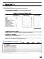
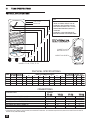
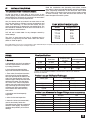
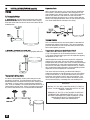
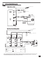
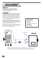
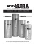
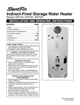
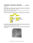
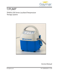
Installation & Operating Instructions
INDIREC T WATER HEATERS
TO THE INSTALLER: This manual is the
property of the owner and must be affixed
near the water heater for future reference.
TO THE OWNER: This water heater should be
inspected annually by a qualified Service
Agency.
WARNING
Improper installation, adjustment,
alteration, service or maintenance can
cause injury or property damage. Refer
to this manual. For assistance or additional information, consult a qualified
Installer or Service Agency.
FOR YOUR SAFETY
Do not store or use gasoline or other
flammable vapors and liquids in the
vicinity of this or any other appliance.
Installation and service must be
performed by a qualified Installer or
Service Agency.
DIVERSIFIED
HEAT TRANSFER, INC.
1710 Flushing Avenue
Ridgewood, NY 11385
Phone: 718-386-6666 / 800-221-1522
Fax: 718-386-7809
www.dhtnet.com
water heater is installed in a multi-story building, on
finished flooring or carpeted surfaces. DHT CANNOT BE
HELD LIABLE for damage caused by water from the
water heater, pressure relief valve, or related fittings.
Closets without drains and carpeted areas are examples
of unsuitable locations for any water heater. Select a
location as centralized within the piping system as
possible. The heater should be located in an area not
subject to freezing temperatures in any location
selected. It is recommended that a suitable drain pan be
installed under the water heater. This pan shall be a
minimum of 50mm (2 in.) deep and have a diameter that
is a minimum of 50mm (2 in.) greater than the diameter
of the water heater. Suitable piping shall connect the
drain pan to a properly operating floor drain.
CONTENTS
I
II
III
SAFETY
PRODUCT SELECTION
PERFORMANCE
RATINGS/SPECS
IV INSTALLATION/PIPING
V
WIRING
VI MAINTENANCE
VII WARRANTY
I
Relief Valve Requirements
Caution: To reduce the risk of excessive pressures and
SAFETY
The warranty on this water heater is in effect only when
the water heater is installed and operated in accordance
with these instructions. The manufacturer of this water
heater will not be liable for any injury or property
damage resulting from failure to comply with these
instructions.
WARNING! This water heater must be installed strictly
in accordance with the instructions enclosed, and local
electrical, fuel and building codes. It is possible that
connections to the water heater, or the water heater
itself may develop leaks. IT IS THEREFORE IMPERATIVE that the water heater be installed so that any
leakage of the tank or related water piping is directed to
an adequate drain in such a way that it cannot damage
the building, furniture, carpeting, adjacent areas, lower
floors of the structure or other property subject to
water damage. This is particularly important if the
temperatures in this water heater, install temperature
and pressure protective equipment required by local
codes. It should be no less than a combination temperature and pressure relief valve certified by a nationally
recognized testing laboratory that maintains periodic
inspection of production of listed equipment or materials, as meeting the latest edition of ANSI Z21.22:
Requirements for Relief Valves and Automatic Gas
Shut-off Devices for Hot Water Supply Systems. This
valve must be marked with a maximum set pressure not
to exceed the marked MAXIMUM working pressure of the
water heater (150 PSI). Install the valve into an opening
provided and marked for this purpose in the water
heater, and orient it or provide tubing so that any
discharge from the valve will exit only within 6 inches
above, or any distance below the structural floor and
cannot contact any live electrical part. The discharge
opening must not be blocked or reduced in size under
any circumstances. The end of the relief pipe opening
should terminate near a floor drain or other suitable
location not subject to blocking or freezing. DO NOT
thread, plug or cap the relief pipe opening.
DANGER
HOT
BURN
• Water temperatures over 125ºF can cause severe burns
instantly, or death from scalds.
• Children, disabled, and elderly are at the highest risk of
being scalded.
• See instruction manual before setting temperature at water
heater.
• Feel water before bathing or showering.
• Temperature limiting valves are available, see manual.
NOTICE
The Techtanium Indirect-fired water heater is deemed to be used in a "commercial
setting" if at any time the unit is operated at a temperature over 150ºF. Refer to warranty
for additional information.
2
II
PRODUCT
P
RODUCT SELECTION/
PERFORMANCE
1. The following guidelines apply to residential systems only. For commercial or institutional installations contact the
factory directly for assistance.
2. Determine the quantity of domestic hot water required. Factors to consider:
a. Estimate typical peak hour demand. Determine the general time of day (morning, noon, evening) when the
most hot water is used. Use chart below to determine potential maximum usage.
Estimate of Peak Domestic Hot Water Usage
Use
Average Gallons of
Hot Water per Usage
Shower
Bath
Shaving
Hands and Face Washing
Hair Shampoo
Hand Dish Washing
Automatic Dish Washing
Food Preparation
Wringer Clothes Washer
Automatic Clothes Washer
20
20
2
4
4
4
14
5
26
32
Times Used During
One Hour
x____________________
x____________________
x____________________
x____________________
x____________________
x____________________
x____________________
x____________________
x____________________
x____________________
Times Used During
One Hour
=
=
=
=
=
=
=
=
=
=
x____________________
x____________________
x____________________
x____________________
x____________________
x____________________
x____________________
x____________________
x____________________
x____________________
Total Peak Hour Demand =
b. Estimate unusual peak draw demand. Whirlpool baths, hot tubs, and mutltiple head showers require large
quantities of hot water in a short period of time. Contact fixture manufacturer for quantity of water required.
Generally speaking, these circumstances can only be met with larger storage volumes.
c. Domestic Water Temperature. Most residential usage will be satisfied with 119ºF water, the temperature
setting recommended by the Consumer Product Safety Commission. Some applications such as laundry and
dishwashers may require a higher temperature.
Ratings can be improved by increasing Techtanium thermostat setting and using a mixing valve to temper the
hot water to the proper temperature. When temperatures greater than 119ºF are required, use a mixing valve at
the outlet of the water heater or anti-scald fittings at point of use.
PERFORMANCE RATINGS
CAPACITY (Gallons)
HEAT EXCHANGER SURFACE AREA SQ.FT.
RECOMM. FLOW RATE GPM (Boiler Water)
PRESSURE DROP FT. HD. (Heat Exchanger)
FIRST HR. RATINGS GPH 90 DEGREE RISE
CONTINUOUS FLOW GPH 90 DEGREE RISE
FIRST HR. RATINGS GPH 70 DEGREE RISE
CONTINUOUS FLOW GPH 70 DEGREE RISE
BOILER SIZE BTU'S REQUIRED
TT-40
TT-55
TT-79
TT-119
40
14
10
2.3
188
160
233
205
120,000
55
14
10
2.3
225
187
277
239
140,000
79
26
14
11
295
240
363
308
180,000
119
26
14
11
376
293
460
377
220,000
NOTE: ABOVE RATINGS BASED ON BOILER MAINTAINING TEMPERATURE OF 180 DEGREES FAHRENHEIT.
3
III
TANK SPECIFICATIONS
PHYSICAL SPECIFICATIONS
KEY
A-TANK TOP
B-TEMP. & PRESS. RELIEF VALVE
C-DOMESTIC HOT WATER OUTLET
D-RECIRCULATION(TT-79 & TT-119)
E-BOILER WATER INLET(SUPPLY)
F-CONTROL
G-DOMESTIC COLD WATER INLET
H-BOILER WATER OUTLET(RETURN)
TANK JACKET
INSULATION
A
B
C
INDIREC T WATER HEATER
D
E
DOMESTIC HOT
WATER OUTLET
F
H
INSPECTION PORT
G
MODELS: TT-40, TT-55, TT-79
MODELTT-119
PHYSICAL SPECIFICATIONS
MODEL DIAMETER VOLUME
OF TANK (Gallons) A
TT-40 20”
40
45
58
TT-55 20”
55
71
TT-79 22”
79
68
TT-119 28"
119
HEIGHT TO CONNECTION (inches)
B
C
D
E
F
G
H
37 1/4
49 5/8
61 1/2
58 1/4
35 5/8
48
61 1/4
68
N/A
N/A
47 7/8
48 7/16
35
35
54 5/8
42
20
20
40 1/4
33 7/8
10 7/16
10 7/16
10 7/8
13
8 7/8
8 7/8
10 1/4
8 7/8
COIL SURFACE WEIGHT (Lbs.)
(Square Feet) NET SHIPPING FILLED
14
116 124 449
14
118 143 576
26
232 243 737
26
333 355 1324
CONNECTIONS
DESCRIPTION
TEMP. & PRESS. RELIEF VALVE
DOMESTIC HOT WATER OUTLET
DOMESTIC COLD WATER INLET
BOILER WATER OUTLET (RETURN)
CONTROL
BOILER WATER INLET (SUPPLY)
RECIRCULATON (TT-79, TT-119)
MODEL
TT-40
TT-55
TT-79
TT-119
3/4”
3/4”
3/4”
1”
1/2“
1”
–
3/4”
3/4”
3/4”
1”
1/2“
1”
–
3/4”
1”
1”
1”
1/2“
1”
3/4”
3/4”
1”mpt
1”mpt
1”
1/2“
1”
3/4”
NOTES: 1) All fittings are female thread connections except for the Domestic Hot and Cold on the TT-119. 2) TT-119 supplied with adapter
to increase from 1" Male to 1 1/4" Female, for Domestic Hot and Cold. 3) TT-119 has inspection Port(with access near bottom of tank for
removal of any sediment buildup).
4
Read the Installation and Operating Instructions manual
thoroughly. Follow recommended piping and wiring diagrams. Upon completing installation, fill the tank with water. While
The Location of the Techtanium heater.
filling it leave a hot water faucet open until a steady stream
Locate the heater so that there is easy access to the of water is flowing. Then, shut the faucet and check for any
control, piping, valves, drain and heater for future servicing leaks thoughout the entire system.
and maintenance. The heater is to be kept in an area where
it is not exposed to freezing temperatures.
IV
INSTALLATION/PIPING
Also, the heater must be located in an area where a leak
(eg. from the piping or fittings, from any temperature and
relief valve discharge, or from the tank itself), will not
cause personal harm or damage the surrounding area. The
tank should be installed in an area with a floor drain or in a
pan suitable for water heaters.
TANK WEIGHT WHEN FILLED.
Model
TT-40
TT-55
TT-79
TT-119
DHT will not be held liable for any damages caused by
water leakage.
The floor or area where the tank is installed must be
capable of supporting the tank when filled with water.
(Refer to Table at right.)
Weight (lbs.)
449
576
737
1324
FOR YOUR SAFETY: Do not store or use gasoline or other flammable vapors or liquids in the vicinity of this or any other appliance. Controls on
this appliance could ignite vapors causing an explosion.
PIPING
Flow Specifications
Model No.
Recommended
Flow Rate
TT-40
TT-55
TT-79
TT-119
10 GPM
10 GPM
14 GPM
14 GPM
1. General
a. All plumbing must be in accordance
with the requirements of the authority having jurisdiction.
b. Use both thread tape and pipe
dope on all mechanical connections.
c. Zone valve (if used) and circulator
must be sized to provide minimum
flow rate specified in the table to the
right, Flow Specifications. Use 1 inch
nominal copper tubing between boiler
and heat exchanger. See the tables
on Friction Loss. Point of emphasis:
using a zone valve without a full bore
may cause high pressure drop which
will adversely affect performance.
Use extreme care when selecting
zone valve.
d. All piping must be adequately
supported.
e. Allow for thermal expansion.
f. Dielectric Unions (recommended) used to electrically isolate the
Techtanium tank from the connected
domestic water piping. This helps to
minimize the possiblity of corrosion
damage.
Heat Exchanger
Pressure Drop
(Ft. Hd.)
2.3
2.3
11
11
Domestic Water
Connection Sizes
3/4”
3/4”
1”
1” MPT
Notes: 1) All fittings are female thread connections except for Domestic Hot and Cold on the
TT-119. 2) TT-119 supplied with adapter to increase from 1" male to 1 1/4" female for
Domestic Hot and Cold.
Friction Loss per 100 Feet of Tubing (psi)
Tubing Type
Type K
Type L
Type M
Flow Rate (gpm)
10 gpm
15 gpm
3.1 psi
2.7 psi
2.3 psi
6.5 psi
5.7 psi
4.7 psi
Friction Loss Allowance for Copper Fittings (feet of straight tubing)
Fitting
Wrought
Cast
90º Elbow
45º Elbow
Tee, Run
Tee, Branch
90º Bend
180º Bend
Gate Valve
1
1
1/2
3
2
2
–
4
2
1/2
5
–
–
1
5
IV
INSTALLATION/PIPING (cont’d)
PIPING
2. Domestic Water
a. Cold Water In. Install brass tee and drain valve (not
provided). Install shutoff valve between water supply
and cold water inlet for ease of service as shown in the
exhibit below.
Expansion Tank
When a back flow device or no return valve is installed in
the system a Thermal Expansion Tank designed for use
with potable water will be required. Locate the expansion
tank on the domestic cold water line near the heater
between the back flow device or no return valve and the
heater (see piping diagrams). Refer to the Thermal expansion Tank manufacturer literature for sizing.
Vacuum Breaker
DHT recommends that a vacuum breaker be installed on
the domestic piping to the heater. The vacuum breaker
protects the heater in the event that tank pressure falls
below atmospheric pressure.
b. Standard Domestic Hot Water Out. A heat trap will
improve energy efficiency by reducing piping heat loss.
Temperature & Pressure Relief Valve( T & P)
A T & P is required on all Techtanium heaters. Install a
T & P valve (long element type) into the separate tapping
designated for the T & P.
Install temperature and pressure protective equipment
required by local codes, but no less than a combination
temperature and pressure relief valve certified as meeting
the requirements for relief Valve and Automatic Shutoff
Devices for Hot Water systems, ANSI Z21.22, by a nationally recognized testing laboratory that maintains periodic
inspection of listed equipment or materials.
Thermostatic Mixing Valve
At times a thermostatic mixing valve may be recommended or required. The thermostatic mixing valve
blends domestic cold water with hot water exiting from
the heater, to yield a more constant desired temperature. Risk of scalding is not eliminated with the use of a
thermostatic mixing valve. Refer to literature provided
by valve manufacturers for recommended installation.
The valve must be oriented, provided with tubing or
otherwise installed so that discharge can exit only within
six (6) inches above, or at any distance below, the structural floor, and cannot contact any electrical part. The
valve must be piped to an area where discharge will not
cause personal injury or damage the surrounding area.
WARNING!
INSTALL A T & P WITH A RATED CAPACITY THAT IS
EQUAL TO OR GREATER THAN THE OUTPUT OF THE
ENERGY SOURCE.
REMOVAL OF THE T & P, OR FAILURE TO REPLACE
TEMPERATURE- PRESSURE RELIEF VALVE, WILL
RELEASE THE MANUFACTURER FROM ANY CLAIM
WHICH MIGHT RESULT FROM EXCESSIVE
TEMPERATURES AND PRESSURES.
6
IV
INSTALLATION/PIPING (cont’d)
PIPING
TANK INSTALLATION
DOMESTIC HOT OUT
DOMESTIC COLD IN
* THERMAL
EXPANSION
TANK
RECIRCULATION
M80/M115
BOILER FEED
BOILER
CONTROLS
BOILER RETURN
MULTIPLE TANK INSTALLATION
DOMESTIC HOT
OUT
DOMESTIC COLD IN
* THERMAL
EXPANSION
TANK
BOILER FEED
BOILER
CONTROLS
BOILER RETURN
TANK CONTROL
TEMP & PRESSURE RELIEF
VALVE
BALL VALVE
CIRCULATOR
ZONE VALVE/
CHECK VALVE
DRAIN VALVE
Notes: 1) Thermal Expansion Tank is required whenever a backflow preventer or no return valve is present in the system. Locate
the Thermal Expansion Tank on the Domestic Cold water line between the heater and backflow preventer or no return valve.
2) The Domestic Hot Water Outlet is at the top of the tank on the TT-119.
7
IV
PIPING DIAGRAM AND INSTRUCTIONS
FOR USE WITH A STEAM BOILER
INSTALLATION:
Install valves B and C a minimum of 6" below
water line G. Keep valves as close to the boiler
as possible. Install boilers drains D and E as close
as possible to valves B and C.
FILL AND PURGE:
Close valves B and C. Attach a hose from an independent
water source to boiler drain E. Attach a hose to boiler
drain D leaving open end of hose in an empty bucket or
basin. Open boiler drain E and D and allow water to fill coil
of tank. Continue to allow water to flow until the flow
is free of air. (smooth, non-sputtering flow) Close boiler
drain D and then boiler drain E.
A
B
C
D
E
F
G
H
I
Open valves B and C and observe boiler water level at the
gauge glass making sure that it remains at its original
level. Fill the potable water side of the tank and purge air
from tank by opening a hot water faucet.
When the power is switched on, the tank aquastat will turn
on pump F and when the temperature of the boiler falls
below the set-point, the boiler will fire.
Water level
Flow control valve
Ball or gate valve
Ball or gate valve
Boiler drain
Boiler drain
Permanently lubricated pump
Water level
Tank Aquastat
Boiler Aquastat
STEAM BOILER
H
A
D
B
G
I
A
F
E
C
NOTE: When installing the Techtanium Indirect Water Heater with a steam boiler, the water flow (direction)
is reversed through the tank coil (heat exchanger). The boiler water enters at the bottom of the coil and
exits from the top of the coil. At no time should live steam be used in the tank coil (heat exchanger).
8
V
WIRING
All wiring must be done in accordance with the tank the set of contacts make (close) and
National, State and local codes. Adhere to the when the temperature rises the contacts break
National Electric Code - ANSI/NFPA 70-1990 in (open).
the absence of any other codes.
The aquastat should be tied into the boiler
Power must be shut off before installing or system and controls. When the tank calls for heat
servicing the heater. A separate shut off switch the aquastat contacts close and signal the boiler
should be installed to support future servicing or controls, allowing the boiler to maintain
an emergency shut down. The entire heating temperature and proper operation of the tank
system should have its own designated electrical circulator.
circuit.
DHT recommends the use of a priority control to
The Techtanium heater operates in much the help the boiler maintain desired temperature and
same way as an additional heating zone, either satisfy the tank's BTU requirements.
utilizing the same circulator as household
heating or its own circulator. The heater The Techtanium heater recovery ratings are
temperature is maintained by the use of an based on the boiler's ability to mainatain 180
immersion type aquastat. The aquastat is degrees Fahrenheit. It is important that the
installed into the immersion well on the heater installer, plumber or heating technician
and secured by tightening the set screw or responsible for installing the heater, make
certain that the boiler capacity (BTU) is adequate
clamp.
to satisfy the heater's BTU requirements.
The aquastat operates in much the same way as
a thermostat. When the temperature falls inside
Water temperature over 125ºF. can
cause severe burns instantly or death
from scalds.
Children, disabled and elderly are at
highest risk of being scalded.
See instruction manual before setting
temperature at water heater.
Feel water before bathing or
showering.
Temperature limiting valves are
available, see manual.
9
V
WIRING (cont’d)
TANKLESS COIL BOILER APPLICATION - PRIORITY FIGURE 3a.
Operation: When any thermostat calls for
heat, the boiler is given a signal to start. The appropriate circulator is energized
only when the boiler temperature is above
the set low limit.
Priority Operation: When zone 6 is
switched to the priority setting and is
actuated, all other zones will stop
operation until zone 6 is satisfied. When
zone 6 is not switched to priority, all zones
will operate independently.
10
Jumper Placement: REMOVE the jumper
between terminals ZC and ZR. Connect
terminal ZC to ZC terminal on the
aquastat control. Connect terminal ZR to
ZR terminal on the aquastat control.
Confirm polarity is consistent between
boiler aquastat and switching relay.
Power Input: Connect 120 volt as power
input to terminals N and H. Neutral wire to
terminal N. Hot wire to terminal H.
V
WIRING (cont’d)
COLD START BOILER APPLICATION - PRIORITY FIGURE 3b.
TACO SR504 & SR506
SWITCHING RELAYS
THERMOSTAT
TECHTANIUM
TEMP CONTROL
T
ZONE 6
PRIORITY
ON
ZONE 1 ZONE 2ZONE 3ZONE 4ZONE 5ZONE 6
OFF
SIX ZONE SWITCHING RELAY
WITH OPTIONAL PRIORITY
SR 506
120 V RELAY
24 VAC
POWER
POWER
ZONE 1
ZONE 2
ZONE 3
ZONE 4
ZONE 5
ZONE 6
ZONE 1 ZONE 2ZONE 3ZONE 4ZONE 5ZONE 6 POWER
X X
INPUT
END SWITCH ZC ZR
120 VOLT CIRCULATORS
FUSE 1 AMP
TO: "TT" ON BOILER
JUMPER
TECHTANIUM
CIRCULATOR
120 VAC OUTPUT
Operation: When any thermostat calls for
heat, the appropriate circulator is
energized and the isolated end switch (X
and X) will start the boiler.
Jumper Placement: The jumper should be
placed between terminals ZC and ZR.
Connect the isolated end switch to the
aquastat control on the boiler.
Priority Operation: When zone 6 is
switched to the priority setting and is
actuated, all other zones will stop
operation until zone 6 is satisfied. When
zone 6 is not switched to priority, all zones
will operate independently.
Power Input: Connect 120 volt as power
input to terminals N and H. Neutral wire
to terminal N. Hot wire to terminal H.
11
V
WIRING (cont’d)
???????????????????????????????????????????????????
ZONING
WITH CIRCULATORS USING R8182D AND R845A RELAY?
ZONING
WITH CIRCULATORS USING L8124 E-F AND R845A RELAY?
?????????????????????????????????????????????????????
12
V
WIRING (cont’d)
???????????????????????????????????????????????????????????????
??
USING
L8148A OR L8152A COLD START BOILER CONTROL WITH CIRCULATORS
???????????????????????????????????????????????????????????????
??
USING
L8143A OR L8152A COLD START BOILER CONTROL WITH ZONE VALVES
13
VI
MAINTENANCE
To ensure efficient and safe operation, DHT recommends
the servicing of the heater by a competent service technician.
Lime or Sediment Buildup (Every 6 months)
To reduce the buildup of lime or sediment it is recommended that the tank be flushed every six months.
1. Drain the tank through the drain valve at the bottom of
the tank until the water is clear.
2. Inspect the tank for any deposits of lime or sediment.
3. Remove lime, scale or deposits using care not to
damage the tank lining.
Magnesium - Anti-Corrosion Anodes (No longer than every
12 months)
The Techtanium Water Heater is provided with two magnesium anti-corrosion anodes, an upper and a bottom anode.
Assessment of the condition of the bottom anode can be
made by judging the condition of the upper anode.
Removal of the anodes:
1. Shut off all power to the heater.
2. Close the domestic cold water supply valve.
3. Open the household hot water taps.
4. Attach a hose to the drain valve located at the bottom of
the heater and allow the heater to drain.
5. Unscrew the anodes.
Temperature & Pressure Relief Valve (Every 12 months)
1. Before manually testing theT & P valve, make sure the
valve is piped in a manner that will not cause harm or
damage any surrounding area.
2. Manually open the relief valve and allow it to flush out
any lime or sediment deposits.
3. Allow the relief valve to snap shut, making sure the seal
closes properly.
OWNER INFORMATION:
MODEL
SERIAL NO.
DATE INSTALLED
INSTALLER NAME
WHOLESALER NAME
ORIGINAL OWNER NAME & ADDRESS
ADDITIONAL INFORMATION
14
EXAMINE THE ANODES AND REPLACE IF THE DIAMETER
IS LESS THAN .40 inches.
6. Replacement of the Anodes -- The use or P.T.F.E. tape is
recommended to ensure watertight connection of the
anodes.
Failure to inspect the anodes may result in premature
failure of the heater.
DIVERSIFIED HEAT TRANSFER, INC.
INDIREC T WATER HEATERS
1710 Flushing Avenue
Ridgewood, NY 11385
Phone: 718-386-6666 / 800-221-1522
LIMITED WARRANTY FOR DIVERSIFIED HEAT TRANSFER, INC. TECHTANIUM™ INDIRECT-FIRED WATER HEATER
Your Techtanium™ indirect-fired water heater is protected by these warranties.
These warranties are applicable to original residential or commercial purchasers only.
THE FOLLOWING WARRANTIES ARE EXCLUSIVE AND ARE GIVEN AND ACCEPTED IN LIEU OF ANY AND ALL OTHER WARRANTIES, EXPRESS OR IMPLIED,
INCLUDING WITHOUT LIMITATION THE IMPLIED WARRANTIES OF MERCHANTABILITY AND FITNESS FOR A PARTICULAR PURPOSE, AND ANY OBLIGATION,
LIABILITY, RIGHT, CLAIM OR REMEDY IN CONTRACT OR TORT, WHETHER OR NOT ARISING FROM DIVERSIFIED HEAT TRANSFER’S NEGLIGENCE, ACTUAL OR
IMPUTED.
THE REMEDIES OF THE ORIGINAL PURCHASER SHALL BE LIMITED TO THOSE PROVIDED HEREIN TO THE EXCLUSION OF ANY OTHER REMEDIES INCLUDING
WITHOUT LIMITATION, SPECIAL, INDIRECT, INCIDENTAL AND/OR CONSEQUENTIAL DAMAGES INCLUDING, BUT NOT LIMITED TO PROPERTY DAMAGE, LOST
PROFIT, OR DAMAGES ALLEGED TO HAVE BEEN CAUSED BY ANY FAILURE OF DIVERSIFIED HEAT TRANSFER TO MEET ANY OBLIGATION UNDER THIS
AGREEMENT INCLUDING THE OBLIGATION TO REPAIR AND REPLACE SET FORTH BELOW.
NO AGREEMENT VARYING OR EXTENDING THE FOREGOING WARRANTIES, REMEDIES, OR THIS LIMITATION WILL BE BINDING UPON DIVERSIFIED HEAT
TRANSFER UNLESS IN WRITING AND SIGNED BY A DULY AUTHORIZED OFFICER OF DIVERSIFIED HEAT TRANSFER. DIVERSIFIED HEAT TRANSFER DOES NOT
ASSUME OR AUTHORIZE ANY OTHER PERSON TO ASSUME FOR IT ANY OTHER LIABILITY IN CONNECITON WITH THE SALE OF ITS PRODUCTS.
THIS WARRANTY EXTENDS ONLY TO THE FIRST (ORIGINAL) RETAIL PURCHASER OF THE TANK AND ONLY WHILE THE TANK IS OWNED BY THAT
PURCHASER AND REMAINS AT ITS ORIGINAL LOCATION. CHANGE IN OWNERSHIP OR RELOCATION OF THE TANK SHALL FOREWITH TERMINATE THIS
WARRANTY WITHOUT FURTHER NOTICE.
WARRANTY COVERAGE FOR RESIDENTIAL USAGE - 7 YEARS
The Warranties listed in this section shall apply to Diversified Heat Transfer Techtanium™ indirect-fired water heaters used in a residential setting by
original purchasers only. A “residential setting” as used herein shall mean usage either (a) in a single family dwelling in which the original consumer
purchaser of the indirect-fired water heater resides on a permanent basis or (b) in a multiple family dwelling provided that such Techtanium indirect-fired
water heater services only one family unit in a multiple family dwelling; provided that the term “residential setting” shall not include any usage of the
Techtanium indirect-fired water heater above 150 degrees Fahrenheit.
During the specified warranty period of the indirect-fired water heater, Diversified Heat Transfer Inc., will repair or replace, at its option, without charge, any
indirect-fired water heater having a defect or malfunction that results in a water leak from the outside jacket, inner tank, or heat exchanger as a result of
normal use and service. It is expressly agreed between Diversified Heat Transfer and the original residential purchaser that repair or replacement is the
exclusive and sole remedy of the original purchaser.
Any claim under this warranty must be verified by an authorized Diversified Heat Transfer (also referred to as DHT) representative: if the claim is found to
be valid, DHT will repair or replace the tank as set forth herein, within a reasonable time after verification. If DHT chooses in its discretion to repair any
indirect-fired water heater for which there is a valid warranty claim, DHT shall provide parts that are compatible with the subject indirect-fired water heater,
which parts need not be identical to the original. If DHT chooses, in its discretion, to replace any indirect-fired water heater for which there is a valid warranty
claim, DHT shall replace the subject indirect-fired water heater with the same model or, if such model is not available, with a model which is, in DHT’s
reasonable judgment, the nearest compatible model available at the time of replacement.
If Diversified Heat Transfer is unable to repair or replace or otherwise comply with its liability under these warranties, after a reasonable number of
attempts, then the original consumer purchaser’s sole and exclusive remedy for such breach shall be either a replacement product or a full refund of the
purchase price (exclusive of freight, labor and installation), as determined by Diversified Heat Transfer.
If the original purchaser cannot provide proof of purchase than DHT may request proof of residency dating back to the date of manufacture of the tank. In
such case the warranty period will begin from the date of manufacture as determined by the tank serial number.
WARRANTY COVERAGE FOR COMMERCIAL USAGE - (THREE YEARS)
The warranties listed in this section shall apply to Diversified Heat Transfer Techtanium™ indirect-fired water heaters used in a commercial setting by original
consumer purchasers only. A “commercial setting” as used herein shall mean any usage not falling within the above definition of a “residential setting”. A Techtanium
indirect-fired water heater shall be deemed to be used in a “commercial setting” if at any time it is operated at a temperature above 150 degrees Fahrenheit.
If at the time of a request for service the original business purchaser cannot provide a copy of the original sales receipt, installation bill, or equivalent
document, then the warranty period for the indirect-fired water heater shall be five (3) years from the date of manufacture of the indirect-fired water heater
as determined by the tank serial number.
15
REPLACEMENT TANK - WARRANTY RESIDENTIAL OR COMMERCIAL APPLICATION
For either a residential or commercial application, the following applies to both when a replacement tank is provided for a tank found to be under warranty.
The replacement tank warranty assumes the remaining warranty period left from the original tank purchased.
WHAT IS NOT COVERED BY EITHER OF THESE WARRANTIES
These warranties are void and shall not apply under the following circumstances:
1. The Techtanium™ water heater was not installed or repaired by a heating contractor whose principal occupation is the sale, installation and repair of
plumbing, heating and/or air conditioning equipment.
2. These warranties cannot be considered as a guarantee of workmanship of an installer connected with the installation of the Techtanium water heater, or
as imposing on Diversified Heat Transfer liability of any nature for unsatisfactory performance as result of faulty workmanship in the installation or repair
which liability is expressly disclaimed.
3. The failure or malfunction results from improper or negligent operation, abuse, misuse or maintenance or unauthorized alteration.
4. Malfunctions resulting from, or repairs necessitated by, uses of the indirect-fired water heater for purposes other than that for which it was designed, or
resulting from flood, fire, wind, lightning, freezing or any other natural disaster or act of God, an act of destruction, theft or accident.
5. The original serial number on the indirect-fired water heater or component thereof cannot be readily determined.
6. Any indirect-fired water heater is installed in a setting containing any type of water softener system that is not installed and maintained in accordance
with the manufacturer’s specifications.
7. The Techtanium indirect-fired water heater is used for non-potable applications such as pool or process heating.
8. The failure or malfunction results from failure to keep the tank full of potable water, free to circulate at all times and with the tank free of damaging water
sediment or scale deposits.
9. Components of an indirect-fired water heater which are not defective, but must be replaced during the warranty period as a result of reasonable wear
and tear.
10. Techtanium indirect-fired water heaters which are repaired or altered without prior written approval of Diversified Heat Transfer so as to affect adversely
their reliability.
11. Diversified Heat Transfer Techtanium™ indirect-fired water heaters installed outside of the United States and Canada.
12. Service calls not involving any malfunction or defects and maintenance in the ordinary course.
13. Components of an indirect-fired water heater which are not manufactured expressly for Diversified Heat Transfer; such components are subject only to
those warranties, if any, given by their manufacturers. Diversified Heat Transfer does not adopt and has no responsibility for those warranties.
14. Any Techtanium tank that does not have installed a new temperature and pressure relief valve bearing the American Society of Mechanical Engineers
(A.S.M.E.) listing at the time of installation.
FURTHER LIMITATIONS OF WARRANTIES AND REMEDIES
These warranties give you specific legal rights, and you may also have other rights which vary from state to state. Some states do not allow the exclusion or
limitation of incidental or consequential damages, so this limitation or exclusion may not apply to you.
These are the only written warranties applicable to Diversified Heat Transfer Techtanium™ indirect-fired water heaters manufactured for and sold by
Diversified Heat Transfer. Diversified Heat Transfer neither assumes nor authorizes anyone to assume for it any other obligation or liability in connection with
said Techtanium indirect-fired water heaters.
This warranty does not cover expenses or labor for disassembly, removal, shipment reassembly or reinstallation; the original purchaser will be
responsible for such costs.
Diversified Heat Transfer’s performance under these warranties may be contingent on shipment of components or equipment from suppliers. Diversified
Heat Transfer shall not be liable for any failure or delay in delivery due to any cause beyond its control including without limitation, strike, labor stoppage, a
natural disaster (such as earthquake, flood, fire or storm), political insurrection or the unavailability of components, equipment or supplies.
MAKING A WARRANTY CLAIM
TO FILE A CLAIM UNDER THESE WARRANTIES CONTACT DIVERSIFIED HEAT TRANSFER INC. AT THIS ADDRESS:
1710 FLUSHING AVENUE, RIDGEWOOD, NEW YORK 11385 OR CALL DIVERSIFIED HEAT TRANSFER AT (718) 386-6666 AND ASK FOR CUSTOMER SERVICE.
At the time a claim is filed, the original purchaser must present a copy of the original sales receipt, installation bill, proof of delivery or equivalent
documents evidencing both ownership of the Techtanium™ indirect-fired water heater and installation in the dwelling or commercial property owned by the
original purchaser
This warranty is to be governed by and construed in accordance with the laws of the State of New York without regard to the principles of conflict of laws.
DIVERSIFIED HEAT TRANSFER RESERVES THE RIGHT TO CHANGE SPECIFICATIONS OR DISCONTINUE MODELS WITHOUT NOTICE.
16
15
ation & Operating Instructions
INDIREC T WATER HEATERS
TO THE INSTALLER: This manual is the
property of the owner and must be affixed
near the water heater for future reference.
TO THE OWNER: This water heater should be
inspected annually by a qualified Service
Agency.
WARNING
Improper installation, adjustment,
alteration, service or maintenance can
cause injury or property damage. Refer
to this manual. For assistance or additional information, consult a qualified
Installer or Service Agency.
FOR YOUR SAFETY
Do not store or use gasoline or other
flammable vapors and liquids in the
vicinity of this or any other appliance.
Installation and service must be
performed by a qualified Installer or
Service Agency.
DIVERSIFIED
HEAT TRANSFER, INC.
1710 Flushing Avenue
Ridgewood, NY 11385
Phone: 718-386-6666 / 800-221-1522
Fax: 718-386-7809
www.dhtnet.com