1
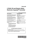
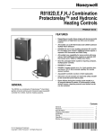
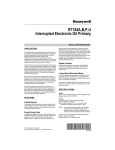
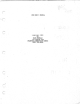
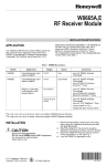
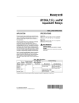
H E A T
T R A N S F E R
P R O D U C T S
INDIRECT FIRED WATER HEATERS
RESIDENTIAL
COMMERCIAL
Heat Transfer Products, Inc., reserves the right to make product changes or updates without notice.
Heat Transfer Products will not be held liable for typographical errors in literature. For questions, please consult the factory.
USING THIS MANUAL
A. INSTALLATION SEQUENCE
Follow the installation instructions provided in
this manual in the order shown. The order of
these instructions has been set in order to
provide the installer with a logical sequence of
steps that will minimize potential interferences
and maximize safety during heater installation.
B. SPECIAL ATTENTION BOXES
Throughout this manual you will see these
special attention boxes to the right of this page
which are intended to supplement the
instructions and make special notice of
potential hazards. These categories are as
defined by the ANSI Z535.A Standard.
DANGER
DANGER indicates an imminently hazardous
situation which, if not avoided, will result in
death or serious injury.
WARNING
WARNING indicates a potentially hazardous
situation which, if not avoided, could result in
death or serious injury.
CAUTION
CAUTION Indicates a potentially hazardous
situtation which, if not avoided, may result in
minor or moderate injury.
CAUTION
CAUTION used without the safety alert symbol
indicates a potentially hazardous situation which,
if not avoided, may result in property damage.
2
CUTAWAY ILLUSTRATION
INTRODUCING THE NEW SUPER-STOR ULTRA
Stainless steel nipple
welded to tank
2" (5.08 cm) Polyurethane
foam insulation on outside;
less than .5˚F (.28˚C) per
hour heat loss (R17)
Hot water outlet, T & P
316L stainless steel
Domestic water connections
(see chart for sizes)
Factory installed
enclosed thermostat well
Plastic jacket
Stainless steel nipple
welded to tank
Boiler supply 1"
Cold inlet & drain
Boiler return 1"
Cupronickel coil assembly
New mechanical heat
exchanger connection
SPECIFICATIONS AND PERFORMANCE RATINGS
ULTRA RESIDENTIAL SERIES
MODEL
DIMENSIONS
CAPACITY
180° BOILER WATER
200° BOILER WATER
HEAT EXCH. RECOMM. PRESSURE FIRST HOUR RATINGS* FIRST HOUR RATINGS*
SURFACE FLOW RATE DROP (FEET)
140°F
115°F
140°F
115°F
HT.
DIA .
SSU-20
27"
19 ¼"
20
15 SQ. FT.
8
6.0
121 gal
168 gal
136 gal
185 gal
SSU-30
39 ½"
19 ¼"
30
15 SQ. FT.
8
6.0
154 gal
212 gal
172 gal
234 gal
SSU-30LB
28 ½"
23 ¼"
30
15 SQ. FT.
8
6.0
169 gal
234 gal
189 gal
257 gal
SSU-45
52 ½"
19 ¼"
45
20 SQ. FT.
10
7.9
212 gal
292 gal
237 gal
322 gal
SSU-60
52 ½"
23 ¼"
60
20 SQ. FT.
10
7.9
266 gal
370 gal
298 gal
405 gal
SSU-80
72"
23 ¼"
80
34 SQ. FT.
12
9.1
330 gal
440 gal
370 gal
503 gal
SSU-119
73 ½"
27"
119
34 SQ. FT.
14
11.3
423 gal
564 gal
474 gal
645 gal
*DOE TEST METHOD BASED ON 90°F. TEMPERATURE RISE, 50°/140° W/ BOILER WATER AT 180°F
TANK SIZE
FLOOR TO
BOILER
SUPPLY
FLOOR TO FLOOR TO
DOMESTIC
TEST
WORKING SHIPPING 180 BOILER 200 BOILER
BOILER
DOMESTIC
CONNECTIONS PRESSURE PRESSURE WEIGHT
BTU/SIZE BTU/SIZE
RETURN
OUT
SSU-20
9"
4 ½"
22"
¾ NPT MALE
300 PSI
150 PSI
60 LBS.
84,000
87,000
SSU-30
9"
4 ½"
34"
¾ NPT MALE
300 PSI
150 PSI
72 LBS.
102,000
117,000
SSU-30LB
9"
4 ½"
22"
¾ NPT MALE
300 PSI
150 PSI
79 LBS.
114,000
131,000
SSU-45
9"
4 ½"
46"
¾ NPT MALE
300 PSI
150 PSI
88 LBS.
141,000
161,000
SSU-60
9"
4 ½"
46"
1" NPT MALE
300 PSI
150 PSI
110 LBS.
174,000
198,000
SSU-80
29"
6"
64.75"
1 ½" NPT MALE
300 PSI
150 PSI
141 LBS.
212,000
241,000
SSU-119
30 ¼"
7 ¼"
66"
1 ½" NPT MALE
300 PSI
150 PSI
210 LBS.
269,000
301,000
NOTE: TANK RECOVERY FROM COLD START WILL BE BETWEEN 10-13 MINUTES WHEN SIZED WITH CORRECT FLOW
RATE, BOILER SIZE, AND PRESSURE DROP RATINGS FROM LIST IN ABOVE CHART.
3
SPECIFICATIONS AND PERFORMANCE RATINGS
DIMENSIONS
MODEL
*
*
**
**
CAPACITY
RECOMM.
FLOW RATE
PRESSURE
DROP (FEET)
180° BOILER WATER
FIRST HOUR RATINGS
140°F
115°F
180° BOILER WATER
2ND HOUR RATINGS
140°F
115°F
HT.
DIA.
SSU-45DW
52 ½"
19 ¼"
45
6 GPM
8.2
70 GAL
108 GAL
40 GAL
63 GAL
SSU-60DW
52 ½"
23 ¼"
60
7 GPM
12.8
90 GAL
144 GAL
50 GAL
76 GAL
SSU-80DW
72"
23 ¼"
80
10 GPM
13.6
138 GAL
215 GAL
72 GAL
113 GAL
SSU-119DW
74"
27"
119
12 GPM
15.9
210 GAL
326 GAL
110 GAL
171 GAL
*DOE TEST METHOD BASED ON 90°F. TEMPERATURE RISE, 50°/140° W/ BOILER WATER AT 180°F
TANK SIZE
FLOOR TO
BOILER
SUPPLY
FLOOR TO
BOILER
RETURN
FLOOR TO
DOMESTIC
OUTPUT
DOMESTIC
CONNECTIONS
TEST
PRESSURE
WORKING
PRESSURE
SHIPPING
WEIGHT
180° BOILER
BTU/SIZE
SSU-45DW
9"
4 ½"
46"
¾" NPT MALE
300 PSI
150 PSI
88 LBS.
107,000
SSU-60DW
9"
4 ½"
46"
1" NTP MALE
300 PSI
150 PSI
110 LBS.
176,000
SSU-80DW
21"
6"
64 ¾"
1 ½" NPT MALE
300 PSI
150 PSI
141 LBS.
208,000
SSU-119DW
22 ¼"
7 ¼"
66"
1 ½" NPT MALE
300 PSI
150 PSI
210 LBS.
231,000
NOTE: TANK RECOVERY FROM COLD START WILL BE BETWEEN 55-65 MINUTES WHEN SIZED WITH CORRECT FLOW
RATE, BOILER SIZE, AND PRESSURE DROP RATINGS FROM LIST IN ABOVE CHART.
ULTRA COMMERCIAL SERIES
DIMENSIONS
MODEL
CAPACITY
180° BOILER WATER
200° BOILER WATER
HEAT EXCH. RECOMM. PRESSURE FIRST HOUR RATINGS* FIRST HOUR RATINGS*
SURFACE FLOW RATE DROP (FEET)
140°F
115°F
140°F
115°F
HT.
DIA .
SSU-45C
42
23 ¼"
45
40 SQ. FT.
20
6.8
314 gal
414 gal
351 gal
477 gal
SSU-60C
52 ½"
23 ¼"
60
40 SQ. FT.
22
9.2
354 gal
467 gal
396 gal
539 gal
SSU-80C
72"
23 ¼"
80
68 SQ. FT.
24
10.0
490 gal
647 gal
548 gal
745 gal
SSU-119C
74"
27"
119
68 SQ. FT.
28
12.7
637 gal
841 gal
713 gal
970 gal
*DOE TEST METHOD BASED ON 90°F. TEMPERATURE RISE, 50°/140° W/ BOILER WATER AT 180°F
TANK SIZE
180° BOILER WATER
200° BOILER WATER
FLOOR TO FLOOR TO FLOOR TO
DOMESTIC
TEST
WORKING SHIPPING
FIRST HOUR RATINGS* FIRST HOUR RATINGS*
BOILER
BOILER DOMESTIC
CONNECTIONS PRESSURE PRESSURE WEIGHT
BTU/SIZE
BTU/SIZE
SUPPLY
RETURN
OUT
SSU-45C
9"
4 ½"
35"
1 ¾" NPT MALE
300 PSI
150 PSI
99 LBS.
215,000
246,000
SSU-60C
9"
4 ½"
46"
1" NPT MALE
300 PSI
150 PSI
115 LBS.
245,000
270,000
SSU-80C
29"
6"
64.75"
1 ½" NPT MALE
300 PSI
150 PSI
141 LBS.
331,000
374,000
SSU-119C
30 ¼"
7 ¼"
66"
1 ½" NPT MALE
300 PSI
150 PSI
210 LBS.
425,000
490,000
NOTE: TANK RECOVERY FROM COLD START WILL BE BETWEEN 10-13 MINUTES WHEN SIZED WITH CORRECT FLOW
RATE, BOILER SIZE, AND PRESSURE DROP RATINGS FROM LIST IN ABOVE CHART.
CONTINUOUS FLOW PERFORMANCE CALCULATION
FIRST HOUR RATING – (.75 x TANK CAPACITY) = CONTINUOUS FLOW
EXAMPLE: SSU-45C = 314 – (.75 x 45) = 280.25
(FHR)
(CONTINUOUS FLOW)
4
REDUCED BOILER INPUT SIZING GUIDE
NOTE: IT IS NOT RECOMMENDED TO REDUCE BOILER INPUT WHEN USING DOUBLE
WALL TANKS.
MODEL
GROSS OUT GROSS OUT GROSS OUT GROSS OUT GROSS OUT GROSS OUT GROSS OUT
BTU/HR
BTU/HR
BTU/HR
BTU/HR
BTU/HR
BTU/HR
BTU/HR
200,000
220,000
240,000
260,000
280,000
300,000
320,000
—
—
—
—
—
—
—
—
—
—
—
—
—
—
—
—
—
—
—
—
—
—
—
—
—
—
—
—
—
—
—
—
—
—
—
—
—
—
—
—
—
—
—
—
—
—
—
—
—
—
—
—
—
—
—
—
SSU-45
A
B
A
B
A
B
A
B
SSU-60
A
B
370
266
370
266
370
266
—
—
—
—
—
—
—
—
SSU-80
A
B
489
359
503
370
503
370
503
—
503
370
503
370
—
—
SSU-119
A
B
457
335
470
345
543
39 9
62 7
46 0
645
474
645
474
645
474
SSU-20
SSU-30
SSU-30LB
SUPERstor’s PRODUCT LINE CONSISTS OF VARIOUS MODELS, AVAILABLE IN DIFFERENT SIZES
CALL THE FACTORY FOR PRODUCT AND WARRANTY INFORMATION!
"DW" (double wall heat exchanger) models are available in the 45, 60, 80, and 119 U.S. gallon sizes
"CB" (coil booster) models operate in conjunction with a tankless heater, to increase hot water storage capacity. Models
are available in 30, 45, 60, 80, and 119 U.S. gallon sizes.
"C" commercial models for dual systems or commercial applications; use one coil for wood boiler, the other for the oil
boiler; adaptable to solar systems as well; also good for hotels, motels, and apartments. Models are available in the
45, 60, 80, and 119 U.S. gallon sizes.
5
PERFORMANCE AND SIZING GUIDELINES
DETERMINE AMOUNT OF DOMESTIC HOT WATER NEEDED, THEN USE THE CHARTS
BELOW TO OPTIMIZE SUPER STOR ULTRA V.S. BOILER SIZING.
COLD START BOILERS:
A. LESS THAN 90 SECONDS TO HEAT UP TO TEMPERATURE
B. GREATER THAN 90 SECONDS TO HEAT UP TO TEMPERATURE
NOTE: FIRST DRAW AT 140° F. (FOR PERFORMANCE AT 115° F, MULTIPLY BY 1.56 FOR
MINUTES OF WATER DRAW)
MODEL
SSU-20
SSU-30
SSU-30LB
SSU-45
SSU-45C
SSU-60
SSU-60C
SSU-80
SSU-80C
SSU-119
SSU-119C
2.0 GPM
9.5
8.5
16.0
14.0
18.0
17.0
23.0
18.0
2.5 GPM
8.0
7.5
13.0
12.0
14.0
12.0
18.0
15.0
3.0 GPM
7.0
6.5
10.0
9.0
12.0
10.0
14.0
13.0
45.0
24.0
26.0
3.5 GPM
5.5
5.0
7. 5
7.0
9.0
8.0
11.0
10.0
29.0
18.0
A
B
A
B
4
4
4
4
4
4
4
4
4
4
4
4
4
4
4
4
A
B
A
B
4
4
4
4
4
4
4
4
4
4
4
4
A
B
A
B
4
4
4
4
4
4
4
4
4
4
4
4
A
B
A
B
A
B
A
B
A
B
4
4
4
4.0 GPM
4.5
4.0
6. 0
5.5
6.5
6. 0
8. 5
7.5
20.0
16.0
4.5 GPM
4.0
3.5
5.5
5.0
6.0
5.5
7.5
7.5
17.0
13.0
5.0 GPM
3.5
3.0
5.0
4.5
5.5
5.0
7.0
6.5
14.0
10.0
36.0
29.0
4
4
30.0
19.0
46.0
30.0
22.0
12.0
29.0
21.0
4
4
4
4
4
4
4
4
4
4
4
4
4
4
4
4
4
4
4
4
4
4
4
4
4
4
4
4
4
4
4
4
NOTE: THIS INFORMATION IS BASED ON BOILER SIZE CONFORMING TO THE MINIMUM
BTU/H REQUIRED TO ACHIEVE FIRST HOUR RATINGS, OBTAINABLE FROM CHART
ABOVE.
4 indicates infinity (continous duty)
6
LOCATION AND OPERATION
NOTE: MINIMUM BTU/H REQUIRED TO ACHIEVE FIRST HOUR RATING
MODEL
GROSS OUTPUT
140° F 90° F ∆T
GAL/HR
127° F 77° F ∆T
GAL/HR
115° F 65° F ∆T
GAL/HR
SSU-20
SSU-30
SSU-30LB
SSU-45
SSU-45C
84,000
102,000
113,000
141,000
215,000
121
154
169
212
314
140
180
198
248
367
168
212
234
292
414
SSU-60
SSU-60C
174,000
245,000
266
354
311
414
370
467
SSU-80
SSU-80C
212,000
331,000
330
490
386
573
440
647
SSU-119
SSU-119C
269,999
425,000
423
637
495
745
564
841
LOCATION
Choose a location for your water heater centralized to the piping system. You must also
locate the Super Stor Ultra where it will not be exposed to freezing temperatures.
Additionally, you will need to place the water heater so that the controls, drain, and inlet/outlets are easily accessible. This appliance must not be installed outdoors, as it is certified as
an indoor appliance, and must also be kept vertical on a level surface.
CAUTION
This unit must be placed where leakage from the relief valve, leakage from the related
piping, or leakage from the tank or connections, will not result in damage to the
surrounding areas, or to the lower floors of the building. A water heater should always
be located in an area with a floor drain or installed in a drain pan suitable for water
heaters. Heat Transfer Products Inc. shall not be held liable for any such water damage.
DANGER
This water heater must not be located near flammable liquids such as Gasoline,
Adhesives, Solvents, Paint Thinners, Butane, Liquefied Propane, etc.; as the controls
of this appliance could ignite vapors causing an explosion.
OPERATING YOUR SUPER STOR ULTRA
“Boiler high limit should be at least 20° higher than the Super Stor Ultra temperature. Set the
low limit of the boiler control at the minimum setting – this will call the burner on, only to
satisfy the tank control. The differential should be 10° to 15°, if your control is adjustable, be
sure that it is in that range. We recommend a temperature setting of 119°F, or in accordance
with local and state codes for normal operation. You may prefer a setting of either higher or
lower temperature, to satisfy your needs. A mixing valve in connection with a high temperature setting may be used for high demand applications (spas, hot tubs, whirlpools)”
7
PLUMBING
CAUTION
Risk of scald injury increases as you increase water temperature! If draining of the
SuperStor Ultra is necessary, open the T & P valve or a hot water tap, to prevent
vacuum buildup in the tank and piping.
PLUMBING
It is mandatory that all plumbing is done is accordance with all local and state plumbing
codes, or warranty will be voided. It is also necessary on all mechanical connections, that
you use both thread tape and pipe dope.
NOTE: WHEN FILLING THE SUPER STOR ULTRA, MAKE SURE THAT YOU OPEN THE HOT
WATER TAP TO RELEASE AIR IN THE TANK AND PIPING.
BOILER CONNECTIONS
Use a 1" nominal minimum tube size, wherever you are using zone valves or circulators;
where a 1" zone valve and 1" tube is required.
On the tank, the boiler supply is to be connected to the outlet of the circulator. The inlet of
the circulator is to be connected to the “HOT OUTLET” side of the boiler. Be sure that the
arrow on the circulator is facing toward the flow direction, (See pressure drop sizing for circulator, page 8). On the tank, the boiler return is to be connected to the return side of the
boiler. The return(s) from heating loop(s) should have a flow check or swing check valve
installed before the return pipe from the tank.
In a steam boiler, the tank supply must be connected to the boiler, well below the minimum
water level. A strainer and a drain valve should be installed at the boiler for periodic draining of scale and sludge. Banging and steam bound traps will occur if the boiler water supplied to heat exchange has steam, or is slightly above the low water cut-out.
It is possible to use live steam in the heat exchanger of the Super Stor Ultra 80 and Super
Stor Ultra 119 only. Consult factory for suggested piping and required components. The
Ultra commercial series Super Stor Ultra 80C and Super Stor Ultra 119C are also included
in this application.
DANGER
Water temperature over 125° F. can cause severe burns instantly,
or death from scalds. Children, disabled, and elderly are at
highest risk of being scalded. See instruction manual before
setting temperature at water heater. Feel water before bathing
or showering! Temperature limiting valves are available.
WARNING
Never use dielectric unions or galvanized steel fittings on any domestic
water connections. Use only copper or brass fittings. Teflon thread
sealant must be used on all connections.
8
PLUMBING AND WIRING
COLD WATER INLET
Use both thread tape and pipe dope and connect an NPT brass tee. On the run, install a
brass drain valve. In the branch, install an NPT male X ¾ “ (minimum) tube adapter. A shut
off valve between city water supply and tank inlet is recommended for ease of service at a
later date. It may be recommended to use a back flow preventer – check your local codes
If a back flow preventer, or a no return valve is used; a thermal expansion tank must be
installed on the cold water supply, between the tank and valve. If the tank is replacing a tankless coil in the boiler, disconnect coil plumbing and use the cold inlet pipe and hot water
outlet pipes for the Super Stor Ultra tank.
CAUTION
DO NOT PLUG TUBE OUTLET IN TANKLESS COIL.
DOMESTIC HOT WATER OUTLET CONNECTION
Use both thread tape and pipe dope, and connect an NPT brass tee. In the run of the brass
tee, install an NPT brass T & P valve long element, for hot water storage tanks (Required by
local codes, but not less than the valve certified as meeting the requirements for relief valves
for hot water heaters (ANSI Z212B-1984), by a nationally recognized lab that maintains periodic inspection of production listed equipment. Make sure that the relief valve is sized to the
BTU/Hour capacity and storage capacity of the water heater. The temperature and pressure
relief valve must be plumbed down so discharge can exit only 6” above, or at any distance
below the structural floor; and cannot be in contact with any live electrical parts.
WARNING
Following installation of the T & P Relief Valve, the valve lever MUST be operated AT
LEAST ONCE A YEAR by the water heater owner to ensure that waterways are clear.
Certain naturally occurring mineral deposits may adhere to the valve, blocking
waterways, rendering it inoperative. When the lever is operated, hot water will
discharge if the waterways are clear. PRECAUTIONS MUST BE TAKEN TO AVOID
PERSONAL INJURY FROM CONTACT WITH HOT WATER AND TO AVOID PROPERTY
DAMAGE. BEFORE operating lever, check to see that a discharge line is connected to
the valve, directing the flow of hot water from the valve to a proper place of disposal. If
no water flows when the lever is operated, replacement of the valve is required. TURN
THE WATER HEATER “OFF” AND CALL A PLUMBER IMMEDIATELY.
This device is designed for emergency safety relief and shall not be used as an
operating control. A relief valve functions, in an emergency, by discharging water.
Therefore, it is essential that a discharge line be piped from the valve in order to carry
the overflow to a safe place of disposal. The discharge line must be same size as the
valve outlet must pitch downward from the valve and terminate at least 6" above a drain
where any discharge will be clearly visible.
9
PLUMBING AND WIRING
CAUTION
RE-INSPECTION OF T&P RELIEF VALVES: Temperature and Pressure Relief Valves
should be inspected AT LEAST ONCE EVERY THREE YEARS, and replaced, if
necessary, by a licensed plumbing contractor or qualified service technician, to ensure
that the product has not been affected by corrosive water conditions and to ensure that
the valve and discharge line have not been altered or tampered with illegally. Certain
naturally occurring conditions may corrode the valve and its components over time,
rendering the valve inoperative. Such conditions can only be detected if the valve and
its components are physically removed and inspected. Do not attempt to conduct an
inspection on your own. Contact your plumbing contractor for a re-inspection to assure
continuing safety.
DANGER
WARNING: FAILURE TO RE-INSPECT THIS VALVE AS DIRECTED COULD RESULT IN
UNSAFE TEMPERATURE OR PRESSURE BUILDUP WHICH CAN RESULT IN SERIOUS
INJURY OR DEATH AND/OR SEVERE PROPERTY DAMAGE.
(Optional to save additional energy dollars) In the bottom of the tee (branch) vertically down,
install an NPT tube adapter. Then install two sweat street 90° elbows. This acts as a thermal
loop to prevent thermal siphon action of hot water
EXPANSION TANK
A thermal expansion tank may be required in the system designed for potable water use, to
offset the expansion of stored water as the temperature is elevated (only in systems where
there is no return valve, a back flow preventer, a water meter, or anywhere pressure can
build up as the water is heated). See typical expansion tank on following page.
CONTROL
Install control element into well and tighten in place with screws on control body. Thermal
conductive paste is recommended. Once the control is operational, it is very important to
make sure the control is maintaining the desired operating temperature.
WIRING
All wiring is to be done in accordance with all applicable local and state codes. Turn off all
power related to the boiler starting and wiring procedures. It is recommended that a disconnect switch be installed between the boiler control and water heater.
10
PLUMBING AND WIRING
PRESSURE DROP SIZING FOR CIRCULATOR
You must have a flow rate, from chart on page 3, on the boiler circulator for the water; or
the published ratings cannot be achieved. The chart below represents the tube run and the
water heater ONLY, and does not include any flow checks or zone valves. That resistance
must be added to the value found in the chart below.
PRESSURE DROP FOR TUBE LENGTH OF
1" COPPER, AND FOR SIX 90 DEGREE
ELBOWS, AND ON TEE ON THE RUN
TUBE SIZE 20'
30'
40'
50'
60'
6 GPM
8.63' 8.93' 9.23' 9.53'
9.8'
7 GPM
11.3' 11.77' 12.24' 12.7' 13.1'
10 GPM 10.25' 11.1' 11.95' 12.8' 13.66'
12 GPM
11.3' 13.2' 14.1'
15'
16'
14 GPM
15.3' 16.4' 17.5' 18.6' 19.8'
14 GPM
15.3' 16.4' 17.5' 18.6' 19.8'
PRESSURE DROP FOR TUBE LENGTH OF
1¼" COPPER, TEN 90° ELBOWS AND 2 TEES
TUBE SIZE
20 GPM
22 GPM
24 GPM
28 GPM
20'
10.9'
14.0'
16.2'
20.4'
30'
11.7'
15.0'
17.5'
22.0'
40'
12.6'
16.0'
18.8'
23.6
50'
13.4'
17.0'
20.1'
25.2
60'
14.3'
18.0'
21.5'
26.8
11
TYPICAL INSTALLATIONS
TYPICAL MIXING VALVE
TYPICAL EXPANSION TANK
TYPICAL INSTALLATION USING ZONE VALVES
12
TYPICAL INSTALLATIONS
TYPICAL INSTALLATION USING CIRCULATORS
TYPICAL INSTALLATION USING A ZONE VALVE (3-WAY)
13
TYPICAL INSTALLATIONS
TYPICAL DP INSTALLATIONS
SUPERSTOR WITH STORAGE TANK TYPICAL INSTALLATION
14
TYPICAL INSTALLATIONS
MULTIPLE TANK INSTALLATIONS
TYPICAL STEAM BOILER
15
WIRING DIAGRAMS
ZONING WITH CIRCULATORS WITH R845 RELAY
ZONING WITH CIRCULATORS USING R8182D AND D.P.S.T. NO RELAY REQUIRED
16
WIRING DIAGRAMS
ZONING WITH CIRCULATORS USING L8124 A, C AND R845A RELAY
ZONING WITH CIRCULATORS USING L8124 E,F AND D.P.S.T. CONTROL. (NO RELAY REQUIRED)
17
WIRING DIAGRAMS
ZONING WITH CIRCULATORS WITH R182D AND R845A RELAY
USING CONTROL WITH BUILT IN IDPST SWITCH WITH NO RELAY REQUIRED
18
WIRING DIAGRAMS
ZONING WITH CIRCULATORS USING L8124 A, C AND R845A RELAY
ZONING WITH CIRCULATORS USING L8124 A,C AND D.P.S.T. (NO RELAY REQUIRED)
19
WIRING DIAGRAMS
USING L8148A OR L8152A COLD START BOILER CONTROL WITH CIRCULATORS
PRIORITY ZONE WITH CIRCULATORS
20
WIRING DIAGRAMS
USING L8148A OR L8152A COLD START BOILER CONTROL WITH ZONE VALVES
PRIORITY ZONE WITH ZONE VALVES
21
TROUBLESHOOTING
TROUBLESHOOTING YOUR SUPER STOR ULTRA
NO HOT WATER
PROBLEM:
A. ZONE VALVE NOT OPENING
B. CIRCULATOR NOT OPERATING
C. TANK CONTROL SET TOO LOW
D. BOILER CONTROL SET TOO LOW
E. WIRING INCORRECT
F. TANK CONTROL FAILURE
G. ZONE VALVE FAILURE
H. CIRCULATOR FAILURE
I. AIR TRAP IN LOOP
POSSIBLE SOLUTION
A. OPEN MANUALLY TO CHECK
B. CHECK OR REPLACE
C. RAISE TANK TEMPERATURE (SEE WARNING THIS SECTION)
D. RAISE BOILER TEMPERATURE
E. RECHECK WIRING
F. REPLACE CONTROL
G. REPLACE VALVE
H. REPLACE CIRCULATOR
I. PURGE TO REMOVE AIR
NOT ENOUGH HOT WATER
PROBLEM:
A. ZONE VALVE RESTRICTION
B. CIRCULATOR ARROW REVERSED
C. TANK TEMPERATURE TOO LOW
D. BOILER TEMPERATURE TOO LOW
E. BOILER SIZED TOO SMALL
F. DEMAND FLOW RATE TOO HIGH
G. TANK SIZED TOO SMALL
H. DEMAND FLOW RATE TOO HIGH
I. AIR TRAP IN LOOP
I. AIR TRAP IN LOOP
J. HEAT & TANK COME ON TOGETHER
K. NOT ENOUGH SPACE HEAT
L. SLOW RECOVERY
POSSIBLE SOLUTION
A. 1" FULL BORE REPLACE ZONE VALVE
B. REVERSE CIRCULATOR
C. ***RAISE TANK TEMPERATURE (SEE WARNING THIS SECTION)
D. RAISE BOILER TEMPERATURE
E. CHECK SIZING CHART
F. CHECK SIZING CHART
G. CHECK SIZING CHART
H. INSTALL MIXING VALVE, RAISE TANK TEMP (SEE WARNING THIS SECTION)
I. PURGE TO REMOVE AIR
INSTALL FLOW REGULATOR
I. PURGE TO REMOVE AIR
J. RE-CHECK WIRING OR COINCIDENCE
DRAW TANK DOWN AND LOWER HEAT THERMOSTAT. RE-CHECK
K. BOILER SIZED TOO SMALL, CONSULT CHART
L. CIRCULATOR HEAD CAPACITY TOO LOW
T & P VALVE DISCHARGES
PROBLEM:
A. ZONE VALVE RESTRICTION
B. CIRCULATOR ARROW REVERSED
C. TANK TEMPERATURE TOO LOW
D. BOILER TEMPERATURE TOO LOW
E. BOILER SIZED TOO SMALL
F. DEMAND FLOW RATE TOO HIGH
G. TANK SIZED TOO SMALL
H. DEMAND FLOW RATE TOO HIGH
I. AIR TRAP IN LOOP
I. AIR TRAP IN LOOP
J. HEAT & TANK COME ON TOGETHER
K. NOT ENOUGH SPACE HEAT
L. SLOW RECOVERY
22
POSSIBLE SOLUTION
A. 1" FULL BORE REPLACE ZONE VALVE
B. REVERSE CIRCULATOR
C. RAISE TANK TEMPERATURE (SEE WARNING THIS SECTION)
D. RAISE BOILER TEMPERATURE
E. CHECK SIZING CHART
F. CHECK SIZING CHART
G. CHECK SIZING CHART
H. INSTALL MIXING VALVE, ***RAISE TANK TEMP (SEE NOTE BELOW)
I. PURGE TO REMOVE AIR
INSTALL FLOW REGULATOR
I. PURGE TO REMOVE AIR
J. RE-CHECK WIRING OR COINCIDENCE
DRAW TANK DOWN AND LOWER HEAT THERMOSTAT. RE-CHECK
K. BOILER SIZED TOO SMALL, CONSULT CHART
L. CIRCULATOR HEAD CAPACITY TOO LOW
TROUBLESHOOTING
HOT TUBS, SPAS, MULTIPLE SHOWERS, HIGH DEMAND
PROBLEM:
A. NOT ENOUGH HOT WATER
B. PRESSURE TOO LOW
C. RECOVERY OF TANK SLOW
D. NOT ENOUGH HOT WATER
POSSIBLE SOLUTION
A. CHECK FLOW RATE AND COMPARE TO CHART
B. CHECK LINE PRESSURE FOR RESTRICTION
C. SLOW START UP BOILER, SEE CHART
D. BOILER SIZED TOO SMALL, SEE CHART
DEMAND TOO GREAT, CHECK FLOW RATES AND COMPART TO CHART.
INSTALL MIXING VALVE AND OR A FLOW RESTRICTING VALVE AND
***RAISE TANK AND BOILER TEMPERATURE (SEE WARNING THIS
SECTION).
WARNING
When raising tank temperature, you increase the risk of scalding – Please use a water
tempering or mixing valve and extreme caution. Consult codes for conformance.
23
© Copyright 2006, 2005 Heat Transfer Products, Inc.
LP-83 REV. 1/1/07