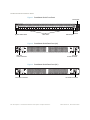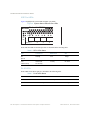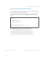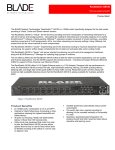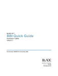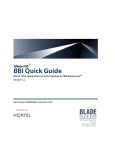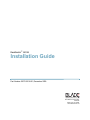
1
RackSwitch™ G8124 Installation Guide Part Number: BPP-00018-01, December 2009 2350 Mission College Blvd. Suite 600 Santa Clara, CA 95054 www.bladenetwork.net RackSwitch G8124 Installation Guide Copyright © 2009 BLADE Network Technologies, Inc., 2350 Mission College Blvd., Suite 600, Santa Clara, California, 95054, USA. All rights reserved. Part Number: BPP-00018-01. This document is protected by copyright and distributed under licenses restricting its use, copying, distribution, and decompilation. No part of this document may be reproduced in any form by any means without prior written authorization of BLADE Network Technologies, Inc. Documentation is provided “as is” without warranty of any kind, either express or implied, including any kind of implied or express warranty of non-infringement or the implied warranties of merchantability or fitness for a particular purpose. U.S. Government End Users: This document is provided with a “commercial item” as defined by FAR 2.101 (Oct. 1995) and contains “commercial technical data” and “commercial software documentation” as those terms are used in FAR 12.211-12.212 (Oct. 1995). Government End Users are authorized to use this documentation only in accordance with those rights and restrictions set forth herein, consistent with FAR 12.211- 12.212 (Oct. 1995), DFARS 227.7202 (JUN 1995) and DFARS 252.227-7015 (Nov. 1995). BLADE Network Technologies, Inc. reserves the right to change any products described herein at any time, and without notice. BLADE Network Technologies, Inc. assumes no responsibility or liability arising from the use of products described herein, except as expressly agreed to in writing by BLADE Network Technologies, Inc. The use and purchase of this product does not convey a license under any patent rights, trademark rights, or any other intellectual property rights of BLADE Network Technologies, Inc. BLADE Network Technologies, the BLADE logo, BLADEHarmony, BNT, NMotion, RackSwitch, Rackonomics, RackSwitch Solution Partner, ServerMobility, SmartConnect and VMready are trademarks of BLADE Network Technologies. All other names or marks are property of their respective owners. Originated in the USA. 2 BPP-00018-01, December 2009 Contents Preface 5 Who Should Use This Book 5 Related Documentation 5 How to Get Help 6 Chapter 1: RackSwitch G8124 Description and Specifications RackSwitch G8124 Features 7 Performance 7 Management Features 7 Software Features 8 Switch Components 9 Hardware Options 9 Switch Unit 9 Switch Ports 12 LEDs 15 Technical Specifications 17 Physical Characteristics 17 Environmental Specifications 17 Power Specifications 18 Ordering Information 19 Chapter 2: Installing the RackSwitch G8124 21 Required Tools 21 Package Contents 21 Environmental Requirements 22 Preventing Electric Shock 22 Preventing Electrostatic Discharge 23 Installing the RackSwitch G8124 in a Standard Equipment Rack Installing the RackSwitch G8124 in an iDataPlex Rack 26 Installing the RackSwitch G8124 in a 4-post Rack 29 BPP-00018-01, December 2009 7 23 3 RackSwitch G8124 Installation Guide Initializing the RackSwitch G8124 32 Default Configuration 33 Configuring an IP Interface 34 Using the Boot Management Menu 35 Installing an SFP or SFP+ Transceiver 36 SFP+ Optical Transceiver 36 SFP Copper Transceiver 37 Troubleshooting 38 System LEDs Do Not Light 38 Port link LED Does Not Light 38 Temperature Sensor Warning 38 Switch Does Not Initialize (Boot) 39 Appendix A: Safety and Compliance Statements Safety Messages 41 Compliance Statements 46 4 Contents 41 BPP-00018-01, December 2009 Preface This Installation Guide provides information and instructions to install a BLADE Network Technologies RackSwitch G8124. For information about configuration and management of the switch, refer to the Command Reference and the product release notes. Who Should Use This Book This Installation Guide is intended for network installers and system administrators engaged in configuring and maintaining a network. It assumes that you are familiar with your RackSwitch G8124, your Web browser, Ethernet concepts, IP addressing, the IEEE 802.1D Spanning Tree Protocol, and SNMP configuration parameters. Related Documentation For documentation about configuring your switch, see the RackSwitch G8124 Application Guide and Command Reference. For details about the switch information, statistics, and configuration parameters, see the RackSwitch G8124 Command Reference. BPP-00018-01, December 2009 5 RackSwitch G8124 Installation Guide How to Get Help If you need help, service, or technical assistance, call Blade Network Technologies Technical Support: US toll free calls: 1-800-414-5268 International calls: 1-408-834-7871 You also can visit our web site at the following address: http://www.bladenetwork.net Click the Support tab. The warranty card received with your product provides details for contacting a customer support representative. If you are unable to locate this information, please contact your reseller. Before you call, prepare the following information: Serial number of the switch unit Software release version number Brief description of the problem and the steps you have already taken Technical support dump information (# show tech-support) Note – In case of any suspected hardware related defect, immediately call the BLADE support line to get the issue resolved. There are no field serviceable parts inside the enclosure and tampering with internal components in an attempt to diagnose hardware or fix defects will void the warranty and the product will be repaired at the customer’s expense. 6 Preface BPP-00018-01, December 2009 CHAPTER 1 RackSwitch G8124 Description and Specifications The RackSwitch G8124 is an all 10Gb Ethernet rackable aggregation switch with unmatched line-rate Layer 2 performance. The G8124 uses a wire-speed, non-blocking switching fabric that provides simultaneous wire-speed transport of multiple packets at low latency on all ports. The G8124 contains twenty-four 10Gb Small Form-factor, Pluggable (SFP+) slots and two 1Gb management ports. The 10Gb SFP+ slots can accept 1Gb copper transceivers, 10Gb optical transceivers, or Direct Attach Cables (DAC). This 1U switch is rack mountable in either the horizontal or vertical direction, depending on your application. You can manage the switch through the console port, or through a network connection using Telnet, a Web browser-based interface, or SNMP-based network management software. RackSwitch G8124 Features This section provides an overview of RackSwitch G8124 features. Performance 240 Gbps throughput (full duplex), non-blocking switching architecture 100% line rate Deterministic port-to-port latency under 300 nanoseconds with 64B packets Management Features Clients Industry standard command-line interface (ISCLI) Browser-based Interface (BBI) BladeHarmony Manager BPP-00018-01, December 2009 7 RackSwitch G8124 Installation Guide Protocols SNMP v1, v2, v3 Secondary NTP support DHCP Software upgrades Dual software images Upgrade via serial, browser, or FTP/TFTP Software Features Security Secure interface login & password RADIUS and TACACS+ SSH v1, v2 HTTPS Secure Browser-based interface Wire-speed filtering with Access Control Lists (ACLs) Layer 2 1024 VLANs (802.1Q), including Private VLANs Multi-link trunking, compatible with Cisco EtherChannel LACP (IEEE 802.3ad) Spanning Tree (802.1D), Multiple Spanning Tree (802.1s), Rapid Spanning Tree (802.1w), with Fast Uplink Convergence 16K forwarding database entries Layer 3 128 configurable interfaces (static or DHCP) IP forwarding IGMP Snooping v1, v2, v3 4K ARP entries RIP v1, v2 OSPF Quality of Service 802.1p priority queues Differentiated Services Code Point (DSCP) support Availability Layer 2 Failover VRRP 8 Chapter 1: RackSwitch G8124 Description and Specifications BPP-00018-01, December 2009 RackSwitch G8124 Installation Guide Switch Components This section describes the RackSwitch G8124 hardware components. Hardware Options The following list provides an overview of G8124 hardware: Switch unit Mounting hardware Standard rack mounting brackets and screws iDataPlex rack mounting brackets and screws 4-post rack mounting brackets and screws Switch Unit The RackSwitch G8124 switch unit is a 1U rack-mountable 10 Gigabit Ethernet switch. You can mount the G8124 in either the horizontal or vertical direction. The RackSwitch G8124 allows for flexible mounting of the switch, as follows: RackSwitch G8124F provides front-to-rear airflow. RackSwitch G8124R provides rear-to-front airflow. DC powered RackSwitch G8124R provides front-to-rear airflow. Ports The switch unit contains twenty-four 10Gb SFP+ slots, plus two management ports, and one serial console port: 24 SFP+ slots 2 RJ-45 management ports 1 RS-232 console port (mini-USB) BPP-00018-01, December 2009 Chapter 1: RackSwitch G8124 Description and Specifications 9 RackSwitch G8124 Installation Guide Figure 1 RackSwitch G8124 Front Panel RJ-45 ports BLADE Rackswitch G8124 B SP L/A A MB MS Stacking 1 2 3 4 5 System status LEDs 6 7 8 9 10 11 12 13 14 15 16 17 18 SFP+ slots 19 20 21 22 23 24 10101 Reset RS-232 port Mgmt Reset button Figure 2 RackSwitch G8124 Rear Panel (AC) IEC 320 Power connector IEC 320 Power connector Figure 3 RackSwitch G8124 Rear Panel (DC) DC Power connector 10 Chapter 1: RackSwitch G8124 Description and Specifications DC Power connector BPP-00018-01, December 2009 RackSwitch G8124 Installation Guide Reset Button The Reset button is recessed within a hole on the front panel. Use a straightened paper clip or similar object to press the Reset button. The Reset button allows technicians to reset the switch, as follows: Press Reset: The switch resets and reloads the configuration files. Press and hold Reset for five seconds: The switch resets and configures all settings to factory defaults. Fans Six internal fans cool the switch unit. If an individual fan fails, the other fans continue to run, and the switch unit continues to operate normally. Fans are not customer replaceable. Fan operation and internal temperatures are monitored. If the air temperature exceeds a desired threshold, the environmental monitor displays warning messages. Note – If a fan fails, the maximum operating temperature drops from +40ºC to +35ºC. The Fan LED blinks if there is a failure of one or more fans. AC Power Supply The G8124 has two redundant 275W AC power supplies. Each internal power supply has an individual IEC 320 power connector on the rear panel. The power cord attaches to a universal grounded AC power source. Caution—To reduce the risk of electric shock, use only power cords that have a grounding path, and always connect the power cord to a properly grounded power outlet. Each power supply can be connected to a separate AC circuit to mitigate the risk of down time during a power failure. When used in a redundant configuration, the dual power supplies have a load-sharing capability that allows each supply to operate at approximately 50 percent of full load. Using redundant power can minimize the power disruption during a power supply failure and extend the expected lifetime of each supply by operating normally in a conservative power mode. There is no power switch on the G8124; the switch unit powers up when power is supplied through the power cord(s). The Power Supply LED indicates the status of the power supplies. The LED blinks when only one power cord is connected or if one power supply fails. The LED lights steady when both power cords are connected and operating. BPP-00018-01, December 2009 Chapter 1: RackSwitch G8124 Description and Specifications 11 RackSwitch G8124 Installation Guide DC Power Supply The DC Powered G8124 has two redundant 250W DC-DC power supplies, operating from 42V to 60V. Each internal power supply has a DC filter input on the rear panel. The DC power sources are connected to the G8124 via the mating connector cable assemblies provided. One end of the cable is connected to the G8124 and the three DC-input leads connect the DC-input power supply to the site power source. The pigtail end of the cable is color coded, as follows: Black: Negative (-48V) Red: Positive (return) Green: Ground Warning—Only trained and qualified personnel can connect this equipment to the site power source. Each power supply can be connected to a separate DC power source to mitigate the risk of down time during a power failure. When used in a redundant configuration, the dual power supplies have a load-sharing capability that allows each supply to operate at approximately 50 percent of full load. Using redundant power can minimize the power disruption during a power supply failure and extend the expected lifetime of each supply by operating normally in a conservative power mode. There is no power switch on the G8124; the switch unit powers up when power is supplied through the DC power source. The Power Supply LED indicates the status of the power supplies. The LED blinks when only one DC power source is connected, and lights steady when both DC power sources are connected. Switch Ports The RackSwitch G8124 switch ports and port options are described below. SFP+ Slots 24 Small Form-factor Pluggable (SFP+) slots are located on the front panel. These slots accept approved copper SFP transceivers, optical SFP+ transceivers, or Direct Attach Cables (DAC). 12 Chapter 1: RackSwitch G8124 Description and Specifications BPP-00018-01, December 2009 RackSwitch G8124 Installation Guide Transceivers are not included with the G8124 switch unit. The following transceivers are available from Blade Network Technologies: Table 1 Recommended SFP+ Transceiver Part number Description BN-CKM-SP-SR SFP+ 10GBase-SR Short Range Optical Fiber Transceiver BN-CKM-SP-LR SFP+ 10GBase-LR Long Range Optical Fiber Transceiver BN-CKM-S-T SFP 1000BASE-T Copper Transceiver BN-CKM-S-SX SFP 1000BASE-T-SX Short Range Optical Transceiver BN-CKM-S-LX SFP 1000BASE-LX Long Range Fiber Transceiver The RackSwitch G8124 accepts any SFP+ Direct Attach Cable that complies to the MSA specification. 10/100/1000Base-T Ports Two 10/100/1000BaseT ports (RJ-45) are located on the front panel. These management ports support in-line management and Control Plane Stacking. The following table describes the RJ-45 connector pin assignments. Table 2 RJ-45 Port pin assignments Pin number Signal Description 1 BI DA+ Bi-directional data pair A positive 2 BI DA- Bi-directional data pair A negative 3 BI DB+ Bi-directional data pair B positive 4 BI DC+ Bi-directional data pair C positive 5 BI DC- Bi-directional data pair C negative 6 BI DB- Bi-directional data pair B negative 7 BI DD+ Bi-directional data pair D positive 8 BI DD- Bi-directional data pair D negative BPP-00018-01, December 2009 Chapter 1: RackSwitch G8124 Description and Specifications 13 RackSwitch G8124 Installation Guide Console Port The RS-232 (mini-USB) serial console port is located on the front panel. An external cable is required to convert to a D9 connector. The following table describes the pinouts for the mini-USB port: Table 3 Console Port pin assignments Pin number Function Pin 1 No connect Pin 2 RS232_SIN Pin 3 RS232_SOUT Pin 4 No connect Pin 5 Ground The following table describes the wiring of the console cable: Table 4 Console Cable pin assignments D9 Pin number Wire Mini-USB Pin number Pin 2 Black Pin 3 Pin 3 White Pin 2 Pin 5 Green Pin 5 Pin 1 Pin 4 D9 Pins 1, 4, and 6 are connected Pin 6 Pin 7 Pin 8 D9 pin 7 is connected to D9 pin 8 Shell Braid 14 Chapter 1: RackSwitch G8124 Description and Specifications Shell BPP-00018-01, December 2009 RackSwitch G8124 Installation Guide LEDs Two LED stacks provide system status and port link status. The system LEDs are described in the following table: Power supplies and AC power input status Fans status MB Stacking master indicator MS Stacking member indicator The following table describes the system LED indications: Table 5 System LEDs Status Function Power Fan Master Member Total Power Failure Off Off Off Off Service Required Blink Green Blink Green Blink Green Blink Green Power Supplies OK Solid Green N/A N/A N/A Power Supply Failure Blink Green N/A N/A N/A Fans OK N/A Solid Green N/A N/A Fan Failure N/A Blink Green N/A N/A Stack Master N/A N/A On Off Stack Backup/Member N/A N/A Off On Stack Error N/A N/A On N/A Non-Stack Member N/A N/A Off Off BPP-00018-01, December 2009 Chapter 1: RackSwitch G8124 Description and Specifications 15 RackSwitch G8124 Installation Guide XGE Port LEDs Figure 4 highlights the system LEDs and SFP+ port LEDs. Figure 4 System Status LEDs and Port LEDs BLADE Rackswitch G8124 SP L/A MB MS Stacking 1 2 3 4 Status and link LEDs for the data port slots are described in the following table. Table 6 SFP+ LEDs Status LED Solid Green Blink Green Off SP: Speed 10Gbps N/A 1Gbps L/A: Link/Activity Valid Link/ No Activity Activity No Link RJ-45 LEDs Status LEDs for the RJ-45 ports are described in the following table. Table 7 RJ-45 LEDs Status LED Solid Green Blink Green Off Link Valid Link Activity No Link Speed 100/1000Mbps N/A 10Mbps 16 Chapter 1: RackSwitch G8124 Description and Specifications BPP-00018-01, December 2009 RackSwitch G8124 Installation Guide Technical Specifications This section provides specifications for the RackSwitch G8124. Physical Characteristics Physical characteristics of the RackSwitch G8124F/G81240R switch unit are listed in the following table. Table 8 Physical Characteristics Specification G8124F G8124R Dimensions (H x W x D) 1.73 x 17.3 x 15.0 in. 1.73 x 17.3 x 15.0 in. 4.4 x 43.9 x 38.1 cm. 4.4 x 43.9 x 38.1 cm. Weight 6.4 kg. 6.4 kg. Airflow Front-to-rear Rear-to-front Environmental Specifications Environmental specifications for the RackSwitch G8124F/G8124R switch unit are listed in the following table. Table 9 Environmental Specifications Specification Measurement Temperature, ambient operating 0ºC to +40ºC Temperature (fan failure or power supply failure), operating 0ºC to +35ºC Temperature, storage -20ºC to +70ºC Relative humidity (non-condensing), operating 10 to 90% Relative humidity (non-condensing), storage 10 to 95% Altitude, operating 3,050 m (10,000 feet) Altitude, storage 4,573 m (15,000 feet) BPP-00018-01, December 2009 Chapter 1: RackSwitch G8124 Description and Specifications 17 RackSwitch G8124 Installation Guide Table 9 Environmental Specifications Specification Measurement Acoustic noise less than 65dB Heat dissipation 1100 BTU/hour (maximum) Power Specifications Power specifications for the RackSwitch G8124F/G8124R switch unit are listed in Table 10 and Table 11. Table 10 AC Power Specifications Specification Measurement Number of power supplies 2 (1+1 redundant) AC-input frequency (universal) 50-60 Hz AC-input voltage (universal) 100-240 VAC AC-input current 2.75A (RMS) @ 100VAC 1.15A (RMS) @ 240VAC AC-input fuse 5A (internal) Power supply output power 275W each System power dissipation 200W typical DC-Output voltage 12V nominal DC-Output current 15A (typical) Table 11 DC Power Specifications Specification Measurement Number of power supplies 2 (1+1 redundant) Input Voltage 42VDC-60VDC 48VDC Nominal Input Current 5.2 A Maximum Power supply output power 250W 18 Chapter 1: RackSwitch G8124 Description and Specifications BPP-00018-01, December 2009 RackSwitch G8124 Installation Guide Ordering Information The following table lists the parts that you can order for the RackSwitch G8124 product family. Table 12 RackSwitch G8124 Ordering Information Part number Description Switch BN-8124F-BDL G8124F 24-port GbE Switch (front-to-rear airflow) BN-8124R-BDL G8124R 24-port GbE Switch (rear-to-front airflow) BN-8124F-DC-BDL DC powered G8124R 24-port GbE Switch (front-to-rear airflow) Pluggable Optics BN-CKM-SP-SR SFP+ 10GBase-SR Short Range Optical Fiber Transceiver BN-CKM-SP-LR SFP+ 10GBase-LR Long Range Optical Fiber Transceiver BN-CKM-S-T SFP 1000BASE-T Copper Transceiver BN-CKM-S-SX SFP 1000BASE-T-SX Short Range Optical Transceiver BN-CKM-S-LX SFP 1000BASE-LX Long Range Fiber Transceiver Rack Mounting Kits BN-MNT-EARS RackSwitch 19” EIA 2-Post Rack Mounting Kit BN-4POST-RLS RackSwitch 19” EIA 4-Post Rack Mounting Kit BN-MNT-HZ-RLS RackSwitch 19” EIA 4-Post Rack Mounting Kit for e1350 BN-MNT-DPX-RLS RackSwitch iDataPlex Rack Mounting Kit BPP-00018-01, December 2009 Chapter 1: RackSwitch G8124 Description and Specifications 19 RackSwitch G8124 Installation Guide 20 Chapter 1: RackSwitch G8124 Description and Specifications BPP-00018-01, December 2009 CHAPTER 2 Installing the RackSwitch G8124 This chapter describes how to install and initialize the RackSwitch G8124. Required Tools You need the following tools or equipment to successfully accomplish the installation procedures in this document: Standard flat-blade screwdriver #2 Phillips screwdriver Electrostatic discharge wrist strap Package Contents The basic RackSwitch G8124 package contains the following items: G8124 switch unit (one of the following): G8124F (front-to-rear airflow) G8124R (rear-to-front airflow) Standard rack mount kit Two brackets Screws to attach brackets to the switch unit Screws to attach the switch unit to the equipment rack Mini-USB serial cable Two AC or DC power cords BPP-00018-01, December 2009 21 RackSwitch G8124 Installation Guide Environmental Requirements This section describes the basic environmental requirements for the RackSwitch G8124. Make sure the location where you install the switch meets the following requirements: Install the switch unit in a dry, clean, well-ventilated area. Provide adequate space on all sides of the switch unit, to ensure proper air flow. Make sure that an adequate grounded power supply is within reach of the switch unit. Make sure that twisted-pair cable is routed away from power lines, fluorescent lighting fixtures and other sources of electrical interference. Preventing Electric Shock This product does not contain any user-serviceable parts. Do not remove the cover of this device. The AC G8124 is designed to work with single-phase power systems that have a grounded neutral conductor. To reduce the risk of electric shock, always plug the power cord into a grounded power outlet. Warning—Electrical current from power, telephone, and communication cables is hazardous. To avoid a shock hazard: Do not connect or disconnect any cables or perform installation, maintenance, or reconfiguration of this product during an electrical storm. Connect the power supply only to a properly wired and grounded power source. Connect to properly wired outlets any equipment that will be attached to this product. When possible, use one hand only to connect or disconnect signal cables. Never turn on any equipment when there is evidence of fire, water, or structural damage. Disconnect the power supply, telecommunications systems, networks, and modems before you open the device covers, unless instructed otherwise in the installation and configuration procedures. Disconnect the power supply before installing, uninstalling, or moving this product. 22 Chapter 2: Installing the RackSwitch G8124 BPP-00018-01, December 2009 RackSwitch G8124 Installation Guide Preventing Electrostatic Discharge Electrostatic discharge (ESD) is a discharge of stored static electricity that can damage equipment and impair electrical circuitry. ESD can cause intermittent or complete equipment failures. Use the following guidelines to prevent ESD damage while you install and work with the G8124 and optional equipment: Use anti-static wrist straps. Adjust the strap to provide good skin contact. Properly ground work surfaces and equipment racks for protection against electrostatic discharge. Avoid contact between equipment and clothing. An anti-static wrist or ankle strap protects the equipment from ESD voltages on the body; ESD voltages on clothing also can cause damage. Do not touch connector pins. Installing the RackSwitch G8124 in a Standard Equipment Rack This section describes how to install the RackSwitch G8124 in a standard 19-inch equipment rack. For information about mounting the G8124 in other rack types, refer to the following sections: “Installing the RackSwitch G8124 in an iDataPlex Rack” on page 26 “Installing the RackSwitch G8124 in a 4-post Rack” on page 29 The following table lists the parts included in the standard mounting kit. Table 13 BN-MNT-EARS 2-Post Rack Mount Kit Item number Part number Description Quantity 1 BMM-00056-00 Bracket 2 2 BMC-00049-00 M4 screws 8 3 BMC-00056-00 M6 screws 4 4 BMC-00015-01 M6 locking washers 4 5 BMC-00069-00 M6 clip nuts 4 6 BMC-00084-00 M6 cage nuts 4 BPP-00018-01, December 2009 Chapter 2: Installing the RackSwitch G8124 23 RackSwitch G8124 Installation Guide Caution—Do not stack other devices on top of the switch unit in the rack. The mounting brackets cannot support multiple devices. Use mounting brackets to secure each device to the rack. Perform the following steps to mount the RackSwitch G8124. 1. Use the M4 screws to attach a mounting bracket to each side of the switch. Torque the screws to approximately 30 inch-pounds (3.5 Nm). Figure 5 Attaching the Mounting Brackets 24 Chapter 2: Installing the RackSwitch G8124 BPP-00018-01, December 2009 RackSwitch G8124 Installation Guide 2. Slide the switch into the rack as illustrated. Figure 6 Rack-mounting the Switch Unit 3. Use M6 screws, washers, and clip nuts to secure the switch unit to the rack. Torque the screws to approximately 30 inch-pounds (3.5 Nm). BPP-00018-01, December 2009 Chapter 2: Installing the RackSwitch G8124 25 RackSwitch G8124 Installation Guide Installing the RackSwitch G8124 in an iDataPlex Rack This section provides general information about installing the RackSwitch G8124 in an IBM iDataPlex rack. The iDataPlex mounting kit allows the switch to be mounted either vertically or horizontally. For information about mounting the G8124 in other rack types, refer to the following sections: “Installing the RackSwitch G8124 in a Standard Equipment Rack” on page 23 “Installing the RackSwitch G8124 in a 4-post Rack” on page 29 The mounting kit is ordered separately. The following table lists the parts included in the iDataPlex mounting kit. Table 14 BN-MNT-DPX-RLS iDataPlex Rack Mount Kit Item number Part number Description Quantity 1 BMM-00098-00 Rear brackets 2 2 BMM-00056-00 Front brackets 2 3 BMM-00066-00 Alignment plate 2 4 BMC-00056-00 M6 screws 8 4 BMC-00015-01 M6 locking washers 8 4 BMC-00069-00 M6 clip nuts 8 5 BMC-00049-00 M4 screws 16 26 Chapter 2: Installing the RackSwitch G8124 BPP-00018-01, December 2009 RackSwitch G8124 Installation Guide Perform the following steps to mount the RackSwitch G8124 into an iDataPlex rack. 1. Use the M4 screws to attach front and rear mounting brackets to each side of the switch unit. Torque the screws to approximately 30 inch-pounds (3.5 Nm). Figure 7 Attaching the Mounting Brackets BPP-00018-01, December 2009 Chapter 2: Installing the RackSwitch G8124 27 RackSwitch G8124 Installation Guide 2. M6 screws, washers, and clip nuts are used to attach the alignment plate. Torque the screws to approximately 30 inch-pounds (3.5 Nm). Figure 8 Attaching the Alignment Plate 3. M6 screws, washers, and clip nuts are used to mount the switch unit into the rack. Torque the screws to approximately 30 inch-pounds (3.5 Nm). Figure 9 Rack-Mounting the Switch Unit 28 Chapter 2: Installing the RackSwitch G8124 BPP-00018-01, December 2009 RackSwitch G8124 Installation Guide Installing the RackSwitch G8124 in a 4-post Rack This section provides general information about installing the RackSwitch G8124 in a 4-post rack, including the IBM e1350 - Type 1410. For information about mounting the G8124 in other rack types, refer to the following sections: “Installing the RackSwitch G8124 in a Standard Equipment Rack” on page 23 “Installing the RackSwitch G8124 in an iDataPlex Rack” on page 26 The 4-post mounting kit is ordered separately. The following table lists the parts included in the standard 4-post mounting kit. Table 15 BN-4POST-RLS 4-Post Rack Mount Kit Item number Part number Description Quantity 1 BMC-00069-00 M6 clip nuts 8 2 BMC-00015-01 M6 locking washers 8 3 BMC-00049-00 M4 screws 16 4 BMC-00056-00 M6 screws 8 5 BMC-00084-00 M6 cage nuts 8 6 BMC-00054-00 M3 screws 4 7 BMM-00125-00 Front bracket 2 8 BMM-00126-00 Rear bracket 2 The e1350 -Type 1410 mounting kit is ordered separately. The following table lists the parts included in the mounting kit. Table 16 BN-MNT-HZ-RLS Type 1410 Rack Mount Kit Item number Part number Description Quantity 1 BMM-00065-00 Left bracket 1 2 BMM-00067-00 Right bracket 1 3 BMM-00089-00 Filler plate 1 4 BMC-00056-00 M6 screws 12 4 BMC-00015-01 M6 locking washers 12 4 BMC-00069-00 M6 clip nuts 8 5 BMC-00049-00 M4 screws 16 BPP-00018-01, December 2009 Chapter 2: Installing the RackSwitch G8124 29 RackSwitch G8124 Installation Guide Perform the following steps to mount the RackSwitch G8124 into a standard 4-post rack. 1. Use the M4 screws to attach a horizontal rail to each side of the switch. Torque the screws to approximately 10 inch-pounds (1.1 Nm). Figure 10 Attaching the Horizontal Rail 2. M6 screws, washers, and clip nuts are used to connect the horizontal rail to the front posts in the rack. Torque the screws to approximately 70 inch-pounds (8.0 Nm). Figure 11 Rack-Mounting the Switch Unit 30 Chapter 2: Installing the RackSwitch G8124 BPP-00018-01, December 2009 RackSwitch G8124 Installation Guide 3. The rear mounting brackets are secured to the rack with M6 screws, washers, and clip nuts. Torque the screws to approximately 30 inch-pounds (3.5 Nm). Figure 12 Attaching Rear Mounting Brackets 4. The front mounting brackets and the rear mounting brackets are secured with M3 screws. Torque the screws to approximately 4 inch-pounds (0.5 Nm). Figure 13 Securing the Rear Bracket to the Front Bracket BPP-00018-01, December 2009 Chapter 2: Installing the RackSwitch G8124 31 RackSwitch G8124 Installation Guide Initializing the RackSwitch G8124 When you plug in the G8124 power cord, the switch initializes automatically. Caution—The G8124 does not have a power switch. When you connect the switch to a suitable power source, the switch powers up immediately. Disconnecting the switch from the power source is the only way to power down the G8124. Always provide the power source in a location that is quickly and safely accessible. The following LEDs indicate the overall system status: Power Supply = Solid Green if both power cords are connected, blinking green if only one power cord is connected Fan = Solid Green if all fans are running, blinking green if there is a fan failure Use the mini-USB console cable to connect the RS-232 serial port on the switch unit’s front panel to a terminal or a PC running a terminal emulation program. You can access the command-line interface to perform initial configuration tasks. The console port’s terminal-emulation requirements are as follows: Default baud rate = 9,600 bps Character size = 8 characters Parity = none Stop bits = 1 Data bits = 8 Flow control = none 32 Chapter 2: Installing the RackSwitch G8124 BPP-00018-01, December 2009 RackSwitch G8124 Installation Guide The switch performs initial self tests, and displays the Password: prompt, similar to the following screen: Memory Test ................................ Production Mode PPCBoot 0.0.0.10 (new flash) Memory Test (0x00) .............................PASSED ... Blade Network Technologies RS 8124 Jan 1 00:01:27 2008: NOTICE-5:Interface Oper Status Indication - Port 7 State UP Password: At the Password: prompt, enter the switch password, and press <Enter>. The default password is admin Default Configuration The switch software contains default configuration files that are loaded at the factory. The default configuration is part of the software; it cannot be deleted or changed. The default settings allow the switch to perform basic functions with minimal effort by the system administrator. BPP-00018-01, December 2009 Chapter 2: Installing the RackSwitch G8124 33 RackSwitch G8124 Installation Guide Configuring an IP Interface To manage the switch using Telnet, SNMP, or a Web browser, you must configure an IP interface. Configure the following IP parameters: IP address Subnet mask Gateway address 1. Log on to the switch. 2. Enter Global Configuration mode. RS G8124> enable RS G8124# configure terminal 3. Configure the management IP address, subnet mask, and gateway. RS RS RS RS RS RS G8124 G8124 G8124 G8124 G8124 G8124 (config)# (config)# (config)# (config)# (config)# (config)# interface interface interface interface interface exit ip-mgmt ip-mgmt ip-mgmt ip-mgmt ip-mgmt address netmask enable gateway gateway 10.10.10.2 255.255.255.0 10.10.10.1 enable Once you configure the IP address for your switch, you can connect to management port A and use the Telnet program from an external management station to access and control the switch. The management station and your switch must be on the same IP subnet. The G8124 supports a command-line interface (CLI) that you can use to configure and control the switch using Telnet. You can use the CLI to perform many basic network management functions. In addition, you can configure the switch for management using an SNMP-based network management system or a Web browser. For more information about using the CLI, refer to the BLADE OS Command Reference for your RackSwitch G8124. 34 Chapter 2: Installing the RackSwitch G8124 BPP-00018-01, December 2009 RackSwitch G8124 Installation Guide Using the Boot Management Menu The Boot Management menu allows you to switch the software image, reset the switch to factory defaults, or to recover from a failed software download. You can interrupt the boot process and enter the Boot Management menu from the serial console port. When the system displays Memory Test, press <Shift B>. The Boot Management menu appears. Resetting the System ... Memory Test ................................ Boot Management Menu 1 - Change booting image 2 - Change configuration block 3 - Xmodem download 4 - Exit Please choose your menu option: 1 Current boot image is 1. Enter image to boot: 1 or 2: 2 Booting from image 2 The Boot Management menu allows you to perform the following actions: To change the boot image, press 1 and follow the screen prompts. To change the configuration block, press 2, and follow the screen prompts. To perform an Xmodem download, press 3 and follow the screen prompts. To exit the Boot Management menu, press 4. The boot process continues. BPP-00018-01, December 2009 Chapter 2: Installing the RackSwitch G8124 35 RackSwitch G8124 Installation Guide Installing an SFP or SFP+ Transceiver The RackSwitch G8124 supports the following Small Form Factor Pluggable (SFP+) transceivers: SFP+ 10GBase-SR Short Range Transceiver (BN-CKM-SP-SR) SFP+ 10GBase-LR Long Range Optical Fiber Transceiver (BN-CKM-SP-LR) SFP 1000BASE-T Copper Transceiver (BN-CKM-S-T) SFP 1000BASE-T-SX Short Range Optical Transceiver (BN-CKM-S-SX) SFP+ Optical Transceiver The G8124 only accepts approved SFP+ transceivers. The SFP+ optical transceiver provides two fiber-optic cable connectors for connecting to external ports. Caution—Class 1 Laser Product Do not look directly into a fiber-optic transceiver or into the ends of fiber-optic cables. Fiber-optic transceivers and fiber-optic cable connected to a transceiver emit laser light that can damage your eyes. Do not leave a fiber-optic transceiver uncovered except when inserting or removing cable. The safety cap keeps the port clean and prevents accidental exposure to laser light. Always inspect and clean the LC connector end faces before making any connections. Perform the following steps to install an SFP+ optical transceiver into a SFP+ slot on the G8124. Note – To avoid damage to the cable or the SFP+ transceiver, do not connect the fiber-optic cable before you install the transceiver. 1. Remove the safety cap and pull the locking lever into the down (unlocked) position. 2. Insert the transceiver into the port until it clicks into place. Use minimal pressure when you insert the transceiver into the slot. Do not use excessive force when you insert the transceiver; you can damage the transceiver or the SFP+ slot. The transceiver has a mechanical guide key to prevent you from inserting the transceiver incorrectly. 3. Pull up the locking lever to lock the transceiver into place. 4. Connect the fiber-optic cable. To remove a SFP+ transceiver, disconnect the fiber-optic cable, and pull down the locking lever to release the transceiver. After you remove the transceiver, replace the safety cap. 36 Chapter 2: Installing the RackSwitch G8124 BPP-00018-01, December 2009 RackSwitch G8124 Installation Guide SFP Copper Transceiver The SFP copper transceiver provides an RJ-45 connector that accepts a standard 10/100/1000Base-T (category 5) cable. Perform the following steps to install an SFP copper transceiver into a 1Gbps SFP slot on the G8124 switch unit. Note – To avoid damage to the cable or the SFP transceiver, do not connect the cable before you install the transceiver. 1. Remove the safety cap and pull the locking lever into the down (unlocked) position. 2. Insert the transceiver into the port until it clicks into place. Use minimal pressure when you insert the transceiver into the slot. Do not use excessive force when you insert the transceiver; you can damage the transceiver or the SFP slot. The transceiver has a mechanical guide key to prevent you from inserting the transceiver incorrectly. 3. Pull up the locking lever to lock the transceiver into place. 4. Connect the cable. To remove a SFP copper transceiver, disconnect the cable, and pull down the locking lever to release the transceiver. After you remove the transceiver, replace the safety cap. BPP-00018-01, December 2009 Chapter 2: Installing the RackSwitch G8124 37 RackSwitch G8124 Installation Guide Troubleshooting This section contains basic troubleshooting information. Use it to help resolve problems that may occur during installation and operation of your switch. If you have problems accessing the switch or working with switch software, refer to your RackSwitch G8124 Application Guide or Command Reference. If you need additional technical assistance, refer to “How to Get Help” on page 6. System LEDs Do Not Light Symptom: The Power Supply and Fan LEDs do not light. Solution: Check the power cord(s) to make sure there is a proper connection to the power plug(s). Verify that AC power is available from the power source. Port link LED Does Not Light Symptom: Port link LED does not light. Solution 1: Check the port configuration in software (refer to your Command Reference). If the port is configured with a specific speed or duplex mode, check the other device to verify that it is set to the same configuration. If the switch port is set to autonegotiate, verify that the other device is set to autonegotiate. Solution 2: Check the cables that connect the port to the other device. Make sure they are connected properly. Verify that you are using the correct cable type. Temperature Sensor Warning Symptom: A temperature warning is displayed on the management console. Solution: Make sure that the air circulation vents on the front and back of the switch are free from obstruction by cables, panels, rack frames, or other materials. Make sure that all cooling fans inside the switch are running. The Fan LED blinks if there is a failure of one or more fans. The following command displays fan status: show sys-info If any fan stops during switch operation, contact Customer Support. It may be necessary to cool the room to a lower temperature or provide a fan for greater air circulation. Resolve the room’s cooling and circulation problems before turning the switch on. 38 Chapter 2: Installing the RackSwitch G8124 BPP-00018-01, December 2009 RackSwitch G8124 Installation Guide Switch Does Not Initialize (Boot) Symptom: All the switch LEDs stay on, and the command prompt does not appear on the console. Solution: The operating system may have been damaged. Use the console port to perform a serial upgrade of the switch software. Refer to your Command Reference. BPP-00018-01, December 2009 Chapter 2: Installing the RackSwitch G8124 39 RackSwitch G8124 Installation Guide 40 Chapter 2: Installing the RackSwitch G8124 BPP-00018-01, December 2009 APPENDIX A Safety and Compliance Statements Safety Messages This section lists the safety messages that appear within this manual. Caution—To reduce the risk of electric shock, use only power cords that have a grounding path, and always connect the power cord to a properly grounded power outlet. ATTENTION—Pour réduire le risque de décharge électrique, employez seulement les cordons de secteur qui ont un chemin fondant, et reliez toujours le cordon de secteur à une sortie correctement au sol de puissance. PRECAUCIÓN—Para reducir el riesgo de descarga eléctrica, utilice solamente los cables eléctricos que tienen una trayectoria que pone a tierra, y conecte siempre el cable eléctrico con un enchufe de energía correctamente puesto a tierra. VORSICHT—Zu das Risiko des Elektroschocks verringern, benutzen Sie nur Netzanschlusskabel, das einen erdenweg haben, und schließen Sie immer das Netzanschlusskabel an einen richtig geerdeten Energienanschluß an. Caution—Only trained and qualified personnel can connect this equipment to the site power source. ATTENTION—Seulement le personnel qualifié et qualifié peut relier cet équipement à la source d'énergie d'emplacement. PRECAUCIÓN—Solamente los personales entrenados y calificados pueden conectar este equipo con la fuente de energía del sitio. VORSICHT—Nur ausgebildetes und qualifiziertes Personal kann diese Ausrüstung an die AufstellungsortEnergiequelle anschließen. BPP-00018-01, December 2009 41 RackSwitch G8124 Installation Guide Warning—Electrical current from power, telephone, and communication cables is hazardous. To avoid a shock hazard: Do not connect or disconnect any cables or perform installation, maintenance, or reconfiguration of this product during an electrical storm. Connect the power supply only to a properly wired and grounded power source. Connect to properly wired outlets any equipment that will be attached to this product. When possible, use one hand only to connect or disconnect signal cables. Never turn on any equipment when there is evidence of fire, water, or structural damage. Disconnect the power supply, telecommunications systems, networks, and modems before you open the device covers, unless instructed otherwise in the installation and configuration procedures. Disconnect the power supply before installing, uninstalling, or moving this product. Avertissement—Le courant électrique des câbles d'alimentation, des câbles téléphonique et des câbles de communication est dangereux. Pour éviter tout risque de choc électrique: Ne branchez, ni ne débranchez aucun des câbles et ne procédez à aucune installation, modification ou reconfiguration pendant un orage électrique. Branchez tous les câbles d’alimentation à une prise électrique correctement câblée et avec prise de terre. Tout équipement interconnecté à ce produit doit lui aussi être branché à une prise de courant proprement installée. Si possible, utilisez une main seulement pour brancher ou débrancher les câbles de signaux. Ne mettez jamais en marche un équipement quand il y a évidence de feu, d'eau, ou de dommages structuraux. Débranchez les câbles d’alimentation, les systèmes de télécommunications, les réseaux, et les modems attachés avant d’ouvrir les couvercles du dispositif, à moins d'instructions particulières notées dans les procédures d'installation et de configuration. Débranchez les cordons d’alimentation avant d’installer, de désinstaller ou de déplacer ce produit. 42 Appendix A: Safety and Compliance Statements BPP-00018-01, December 2009 RackSwitch G8124 Installation Guide Advertencia—La corriente eléctrica de la energía, del teléfono, y de los cables de la comunicación es peligrosa. Para evitar un peligro de la descarga eléctrica: No conecte ni desconecte ninguna cables o no realice la instalación, el mantenimiento, o la reconfiguración de este producto durante una tormenta eléctrica. Conecte la fuente de alimentación solamente con una fuente de energía correctamente atada con alambre y puesta a tierra. Conecte con los enchufes correctamente atados con alambre cualquier equipo que sea atado a este producto. Cuando es posible, utilice una mano para conectar o para desconectar solamente los cables de señal. Nunca gire cualquier equipo cuando hay evidencia del fuego, del agua, o del daño estructural. Desconecte la fuente de alimentación, los sistemas de telecomunicaciones, las redes, y los módems antes de que usted abra las cubiertas del dispositivo, a menos que esté dado instrucciones de otra manera en los procedimientos de la instalación y de configuración. Desconecte la fuente de alimentación antes de instalar, de desinstalar, o de mover este producto. Warnung—Der Strom aus Kraft, Telefon, Kabel-und Kommunikationstechnologien ist gefährlich. Um eine Stromschlaggefahr zu vermeiden: Schließen Sie oder trennen Sie keine Kabel oder führen Sie die keine Installation, Wartung oder Neukonfiguration des Produkts während eines Gewitters. Schließen Sie das Netzteil nur an eine ordnungsgemäß geerdete und geerdete Stromquelle. Verbinden Sie diesem Produkt nur an richtig verdrahtete Stecker. Verwenden Sie nach Möglichkeit nur einer Hand zu verbinden oder trennen Signalleitungen. Kein Gerät einschalten, wenn es Anzeichen für Feuer, Wasser, oder Bauschäden gibt. Trennen Sie die Stromversorgung, Telekommunikation, Netzwerke und Modems, bevor Sie das Gerätedeckel offen, sofern nicht anders in der Installation und Konfiguration angewiesen ist. Trennen Sie das Netzteil vor der Installation, Deinstallation oder Verschieben von diesem Produkt. BPP-00018-01, December 2009 Appendix A: Safety and Compliance Statements 43 RackSwitch G8124 Installation Guide Caution—Do not stack other devices on top of the switch unit in the rack. The mounting brackets cannot support multiple devices. Use mounting brackets to secure each device to the rack. ATTENTION—Ne posez aucun appareil supplémentaire sur le commutateur sans support additionnel. Les supports ne peuvent soutenir plusieurs appareils. Utilisez les supports métalliques pour fixer chaque appareil aux armatures de la baie. PRECAUCIÓN—No apile otros dispositivos encima de la unidad del interruptor en el estante. Los soportes de montaje no pueden apoyar los dispositivos múltiples. Utilice los soportes de montaje para asegurar cada dispositivo al estante. VORSICHT—Stellen Sie keine anderen Geräte auf dem Switch-Einheit im Rack. Die Halterungen können nicht mehrere Geräte aushalten. Montagehalterungen verwenden um jedes Gerät am Rack zu befestigen. Caution—The G8124 does not have a power switch. When you connect the switch to a suitable power source, the switch powers up immediately. Disconnecting the switch from the power source is the only way to power down the G8124. Always provide the power source in a location that is quickly and safely accessible. ATTENTION—Le G8124 ne dispose pas d'un interrupteur de marche/arrêt. Quand vous connectez le cordon d’alimentation à la prise secteur du courant alternatif, le commutateur s’allume immédiatement. La seule manière d'éteindre le commutateur est de débrancher les câbles d'alimentation. Assurez-vous de connecter le câble d'alimentation à une pris électrique facile d’accès et sans risques. PRECAUCIÓN—El G8124 no tiene un interruptor. Cuando usted conecta el interruptor con una fuente de energía conveniente, las energías del interruptor para arriba inmediatamente. La desconexión el interruptor de la fuente de energía es la única manera de accionar abajo el G8124. Proporcione siempre la fuente de energía en una localización que esté rápidamente y con seguridad accesible. VORSICHT—Der G8124 hat keinen Netzschalter. Wenn Sie eine es auf eine geeignete Energiequelle, schaltet es sofort ein. Das Trennen vom Stromversorgung ist die einzige Möglichkeit zum der G8124 auszuschalten. Immer die Stromversorgung an einem Ort verbringen, der schnell und sicher zugänglich ist. 44 Appendix A: Safety and Compliance Statements BPP-00018-01, December 2009 RackSwitch G8124 Installation Guide Caution—Class 1 Laser Product Do not look directly into a fiber-optic transceiver or into the ends of fiber-optic cables. Fiber-optic transceivers and fiber-optic cable connected to a transceiver emit laser light that can damage your eyes. Do not leave a fiber-optic transceiver uncovered except when inserting or removing cable. The safety cap keeps the port clean and prevents accidental exposure to laser light. Always inspect and clean the LC connector end faces before making any connections. ATTENTION—Produit laser de classe 1 Ne regardez pas directement dans un module fibre optique ou dans l'extrémité d’un câble fibre optique. Un module fibre optique et un câble fibre optique sont reliés à un émetteur qui émet un faisceau lumineux pouvant endommager la rétine. Ne laissez jamais un module fibre optique sans capuchon de sûreté excepté lors du branchement ou du débranchement d’un câble fibre optique. Le capuchon de sûreté garde l’orifice du module propre et empêche l'exposition accidentelle au faisceau laser. Inspectez et nettoyez toujours les contours du connecteur LC avant tout branchement. PRECAUCIÓN—Producto Del Laser De la Clase 1 No mire directamente en un transmisor-receptor fiber-optic o en los extremos de cables fiber-optic. Los transmisores-receptores fiber-optic y el cable fiber-optic conectaron con un transmisor-receptor emiten la luz laser que puede dañar sus ojos. No deje un transmisor-receptor fiber-optic destapado excepto al insertar o quitando el cable. El casquillo de seguridad guarda el portuario para limpiar y previene la exposición accidental a la luz laser. Examine y limpie siempre las caras del extremo del conectador del LC antes de hacer cualesquiera conexiones. VORSICHT—Klasse 1 Laser-Produkt Schauen Sie nicht direkt in einem Glasfaser-Transceiver oder in den Enden einer Lichtwellenleiter. Glasfaser-Transceiver-und LWL-Kabel emittieren Laserlicht, dass die Augen schädigen können. Lassen Sie ein Glasfaser-Transceiver zugedeckt , außer beim Einsetzen oder Entfernen von Kabel. Die Schutzkappe hält den Port sauber und verhindert ungewollte Belastungen durch Laserlicht. Ueberprüfen und reinigen Sie den LC-Stecker Enden bevor Sie jegliche Anschlüsse vornehmen. BPP-00018-01, December 2009 Appendix A: Safety and Compliance Statements 45 RackSwitch G8124 Installation Guide Compliance Statements This section contains regulatory compliance statements for the RackSwitch G8124. Blade Network Technologies Commitment to WEEE The EU Directive of the EU Parliament and Council on Waste Electrical and Electronic Equipment (WEEE) became effective on 13 August 2005. Individual EU Member State implementations were made effective, or will be effective, during 2005 and 2006. BLADE is committed to be a responsible member of the global community in providing management of WEEE and is complying with all the obligations pursuant the WEEE Directive and its implementation in National Member State legislation as applicable. Information for pursuing proper means for collection and treatment of WEEE from commercial customers resulting from products put on the market may be obtained by visiting our web site: http://www.bladenetwork.net/weee Federal Communications Commission (FCC) Statement Note: This equipment has been tested and found to comply with the limits for a Class A digital device, pursuant to Part 15 of the FCC Rules. These limits are designed to provide reasonable protection against harmful interference when the equipment is operated in a commercial environment. This equipment generates, uses, and can radiate radio frequency energy and, if not installed and used in accordance with the instruction manual, may cause harmful interference to radio communications. Operation of this equipment in a residential area is likely to cause harmful interference, in which case the user will be required to correct the interference at his own expense. Properly shielded and grounded cables and connectors must be used in order to meet FCC emission limits. Blade Network Technologies, Inc. is not responsible for any radio or television interference caused by using other than recommended cables and connectors or by unauthorized changes or modifications to this equipment. Unauthorized changes or modifications could void the user’s authority to operate the equipment. This device complies with Part 15 of the FCC Rules. Operation is subject to the following two conditions: (1) this device may not cause harmful interference, and (2) this device must accept any interference received, including interference that may cause undesired operation. 46 Appendix A: Safety and Compliance Statements BPP-00018-01, December 2009 RackSwitch G8124 Installation Guide Industry Canada Class A Emission Compliance Statement This Class A digital apparatus complies with Canadian ICES-003. Avis de conformité à la réglementation d’Industrie Canada Cet appareil numérique de la classe A est conforme à la norme NMB-003 du Canada. Australia and New Zealand Class A Statement Attention: This is a Class A product. In a domestic environment this product may cause radio interference in which case the user may be required to take adequate measures. European Union EMC Directive Conformance Statement This product is in conformity with the protection requirements of EU Council Directive 2004/108/EC on the approximation of the laws of the Member States relating to electromagnetic compatibility. Blade Network Technologies, Inc. cannot accept responsibility for any failure to satisfy the protection requirements resulting from a nonrecommended modification of the product, including the fitting of unsupported option cards. This product has been tested and found to comply with the limits for Class A Information Technology Equipment according to CISPR 22/European Standard EN 55022. The limits for Class A equipment were derived for commercial and industrial environments to provide reasonable protection against interference with licensed communication equipment. Attention: This is a Class A product. In a domestic environment this product may cause radio interference in which case the user may be required to take adequate measures. BPP-00018-01, December 2009 Appendix A: Safety and Compliance Statements 47 RackSwitch G8124 Installation Guide NOM Statement (Mexico only) The following information is provided on the devices described in this document in compliance with the safety requirements of the Norma Oficial Méxicana (NOM): Exporter: Blade Network Technologies 2350 Mission College Blvd. Santa Clara, CA, 95054 USA Importer: IMPORSYS, S.A. de C.V.28 de Diciembre No. 22 Col. Avante, C.P. 04460 México, D.F. Input: RackSwitch G8124 G8124F AC 100-240 V~ 1.5 50-60 Hz Chassis power consumption: 275W G8124R AC 100-240 V~ 1.5 50-60 Hz Chassis power consumption: 275W Información NOM (unicamente para México) La información siguiente se proporciona en el dispositivo o en los dispositivos descritos en este documento, en cumplimiento con los requisitos de la Norma Oficial Méxicana (NOM): Exportador: Blade Network Technologies 2350 Mission College Blvd. Santa Clara, CA, 95054 USA Importer: IMPORSYS, S.A. de C.V.28 de Diciembre No. 22 Col. Avante, C.P. 04460 México, D.F. Input: RackSwitch G8124 G8124F AC 100-240 V~ 1.5 50-60 Hz Consumo de energía del chasis:: 275W G8124R AC 100-240 V~ 1.5 50-60 Hz Consumo de energía del chasis:: 275W 48 Appendix A: Safety and Compliance Statements BPP-00018-01, December 2009 RackSwitch G8124 Installation Guide Japanese Voluntary Control Council for Interference (VCCI) Statement Denan Statement (Japan/Nippon only) 本製品を安全にご使用いただくため、以下のことにご注意ください。 • 接続ケーブル、電源コード、AC アダプタなどの部品は、必ず製品に同梱されている添 付品または指定品をご使用ください。添付品・指定品以外の部品をご使用されることは 動作不良、火災の原因となることがあります。 • 同梱されております付属の電源コードを他の機器には使用しないでください。本注意 事項を守らないと、死亡や大怪我など人身事故の原因となることがあります。 KCC/MIC Notice (Republic of Korea only) This device has been approved for use in Business applications only per the Class A requirements of the Republic of Korea Ministry of Information and Communications (MIC). This device may not be sold for use in a non-business application. Observe the Regulatory Marking label on the back or bottom of each switch for specific certification information pertaining to this model. Each RackSwitch G8124 model is approved for shipment to/usage in Korea and is labelled as such, with all appropriate text and the appropriate MIC reference number. BPP-00018-01, December 2009 Appendix A: Safety and Compliance Statements 49 RackSwitch G8124 Installation Guide Toxic / Hazardous Substances and Elements Table (RackSwitch G8124F/G8124R) o: Indicates that the content of the toxic and hazardous substance in all the homogeneous materials of the part is below the concentration limit requirement as described in SJ/T 11363-2006. x: Indicates that the content of the toxic and hazardous substance in at least one homogeneous material of the part exceeds the concentration limit requirement as described in SJ/T 11363-2006. Environmental Protection Use Period (EPUP) Disclaimer: The number provided as the EPUP is provided solely to comply with applicable laws of the People’s Republic of China. It does not create any warranties or liabilities on behalf of BNT to customers. The EPUP assumes that the product will be used under normal conditions in accordance with the BNT operating manual. Blade Part #: BN-8124R-F and BN-8124F-F 50 Appendix A: Safety and Compliance Statements BPP-00018-01, December 2009 RackSwitch G8124 Installation Guide BPP-00018-01, December 2009 Appendix A: Safety and Compliance Statements 51 RackSwitch G8124 Installation Guide 52 Appendix A: Safety and Compliance Statements 2350 Mission College Blvd. Suite 600 Santa Clara, CA 95054 www.bladenetwork.net BPP-00018-01, December 2009