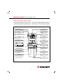
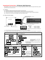
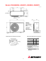
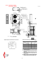
1
FD 8 Series Split Systems
CONTENTS
FDT 8/8
FDT 8/6
Cassette
Cassette
Performance and Engineering data
Performance and Engineering data
Page 1
Page 2
FDT
FDT
FDT
Cassette
Cassette
Cassette
Installation
Space Collars
Engineering drawings
Page 3
Page 5
Page 6
RCD Wired controller
RCD Group Control and set up
Operation, Error Codes
Page 9
Page 10
Page 11
Remote Control
FDEN 8/8
FDEN 8/6
Ceiling
Ceiling
Performance and Engineering data
Performance and Engineering data
Page 12
Page 13
FDEN
FDEN
Ceiling
Ceiling
Installation
Engineering drawings
Page 14
Page 15
Performance and Engineering data
Installation
Engineering drawings
Page 17
Page 18
Page 19
Remote Control
Infra-red Controller
Page 22
Refrigerant Pipework
Installation
Page 23
Low Ambient Control
Installation
Page 24
Electrical Site Wiring
Time Clock/BMS Adaptor
Installation
Wiring adaptor to CnT connection
Page 25
Page 25
SCADE
Superlynk adaptor
Page 26
Condensate Drains
Installation
Page 27
Installation
Engineering Drawings
Page 29
Page 31
Multi Systems
Specification & Installation
Page 38
Safety Information
Back Cover
FDKN 8/8,6
FDKN
FDKN
FDC
FDC
Wall
Wall
Wall
Outdoor Units
Outdoor Units
FDT - 8 Series (Cassette)
FDC - 8 Series (Outdoor)
Technical data for R22 and R407C Systems
SYSTEM REFERENCE
PERFORMANCE
2088
2588
3088
3088(3ph)
4088
5088
Cooling performance nom.
(1)
KW
5.00
5.70
7.10
7.10
10.00
12.50
Cooling U K Conditions
(2)
KW
4.80
5.47
6.82
6.82
9.60
12.00
Sensible Cooling UK
(3)
KW
3.51
4.05
5.05
5.05
6.91
8.28
KW
5.40
6.10
8.00
8.00
11.20
14.00
Heating Performance (HP only)
ELECTRICAL DATA
System Power connection
Mains to outdoor unit first.
Interconnecting wiring - 3 wires + Earth, for cooling, 5 wires + Earth, for Heat Pump
Run current - cooling
A
8.1
9.4
14.4
5.5/ph
8.1/ph
10.3/ph
Start current max. L R A
A
44
51
95
45/ph
53/ph
74/ph
A
20
30
30
15/ph
15/ph
20/ph
FDT208
FDT258
FDT308
FDT308
Recommended Fuse Rating (Local)
INDOOR UNIT ref:
(5)
FDT 8 Series
Dimension - Unit H x W x D
mm
Net Weight
kg
215 x 700 x 700
23
30
Airflow (6)
High / low speed
Sound level at 1 m below unit
high / low
FDT508
320 x 840 x 840
30
Fan Specification
Motor Rating
FDT408
260 x 840 x 840
30
34
Turbo Fan x 1 30
30 x 1
30 x 1
36
W
30 x 1
25 x 1
80 x1
130 x 1
m 3/s
0.23 / 0.16
0.26 / 0.18
0.28 / 0.20
0.28 / 0.20
0.43 / 0.31
0.46 / 0.33
dBA
38 / 33
39 / 35
41 / 35
41 / 35
48 / 40
49 / 43
Safety Control
Internal thermostat for fan motor. Frost protection thermostat.
Condensate Lift Pump – Max lift
(7)
Condensate Connection Size o.d.
mm
700
700
700
700
700
700
mm
25
25
25
25
25
25
Fresh Air Inlet facility
Inlet facility on all models
Exhaust Air Duct facility
Branch duct facility on all models
Refrigerant Control
Pipe Termination Sizes
Capillary tube.
o.d.
ins
5/8
5/8
5/8
5/8
3/4
3/4
o.d.
ins
1/4
3/8
3/8
3/8
3/8
3/8
Filter
Long life filter x 1(Washable)
Remote Control (wired)
Multi function wired controller with alternative temperature sensor
FDC208
OUTDOOR UNIT ref: FDC 8
TECHNICAL DATA
Dimension - Unit H x W x D
mm
Net Weight
kg
FDC258
FDC308
690 X 880 X 290
49
FDC308(3ph)
845 X 880 X 340
55
Fan Specification
74
74
FDC408(3ph)
FDC508(3ph)
1050X 920 X 340
1250 X 920 X 340
90
Propeller Fan x 1
Motor Rating
Sound level at 1 metre in front
101
Propeller Fan x 2
W
55 X 1
55 X 1
55 X 1
55 X 1
40 X 2
65 X 2
dBA
52
52
52
52
54
55
Refrigerant type
R22 OR R407C
Refrigerant factory charge
R22 / R407C
kg
0.98 / 0.98
1.1 / 1.2
1.4 / 1.75
1.4 / 1.75
1.7 / 2.12
1.9 / 2.58
o.d.
ins
5/8
5/8
5/8
5/8
3/4
3/4
o.d.
ins
1/4
3/8
3/8
3/8
3/8
3/8
Maximum pipe run
m
30
30
50
50
50
50
Max height diff. Outdoor unit above / below
m
30 / 15
30 / 15
30 / 15
30 / 15
30 / 15
30 / 15
REFRIGERANT PIPING
Pipe Termination Sizes
NOTES
1
2
3
4
5
6
7
o
o
o
o
Nominal cooling rated at ISO-A, JIS B8616
Outdoor: 35 C DB / 24 C WB Indoor:
27 C DB / 19 C WB
o
o
o
o
U K Cooling
Outdoor: 30 C DB / 20 C WB Indoor:
23 C DB / 17 C WB
Sensible Cooling calculated at UK conditions, at standard air volume.
o
o
o
Heating Performance rated at:
Outdoor
7 C DB / 6 C WB Indoor:
20 C DB
Recommendations are for supply to outdoor unit. Use motor rated fuse or MCB. Requirement may vary depending on site conditions.
CEN & HEN = 1ph
CES & HES = 3ph.
Condensate lift measured from ceiling line.
8 Cooling only systems available in R22 models 2088 & 2588. Cooling only available with R22 FDC 6 Series outdoor units, and all R407C FDC 8 Series.
1
FDT - 8 Series (Cassette)
FDC - 6 Series (Outdoor)
Technical data for R22 and R407C Systems
SYSTEM REFERENCE
PERFORMANCE
3086
3086 (3ph)
4086
5086
Note
Cooling performance nom.
(1)
KW
7.10
7.10
10.20
12.50
Cooling UK Conditions
(2)
KW
6.82
6.82
9.79
12.00
Sensible Cooling UK
(3)
KW
5.05
5.05
7.05
8.28
KW
7.30
7.30
10.50
12.80
Heating Performance (HP only)
ELECTRICAL DATA
System Power connection
Mains to outdoor unit first.
Interconnecting wiring - 3 wires + Earth, for cooling,
5 wires + Earth, for Heat Pump
Run current - cooling
A
16.3
6.0/ph
7.5/ph
10.0/ph
Start current max. L R A
A
89
43/ph
45/ph
68/ph
A
30
15/ph
15/ph
20/ph
FDT308
FDT408
Recommended Fuse Rating (Local)
INDOOR UNIT ref:
(5)
FDT 8 Series
FDT308
Dimension - Unit H x W x D
mm
Net Weight
kg
FDT508
260 x 840 x 840
320 x 840 x 840
30
30
34
Fan Specification
36
Turbo Fan x 1
Motor Rating
Airflow (6)
High / low speed
Sound level at 1 metre below
high / low
W
30 x 1
30 x 1
80 x 1
130 x 1
m 3/s
0.28 / 0.20
0.28 / 0.20
0.43 / 0.31
0.46 / 0.33
dBA
41 / 35
41 / 35
48 / 40
49 / 43
Safety Control
Internal thermostat for fan motor. Frost protection thermostat.
Condensate Lift Pump – Max lift
(7)
Condensate Connection Size o.d.
mm
700
700
700
700
mm
25
25
25
25
Fresh Air Inlet facility
Inlet facility on all models
Exhaust Air Duct facility
Branch duct facility on all models
Refrigerant Control
Pipe Termination Sizes
Capillary tube.
o.d.
o.d.
ins
5/8
5/8
3/4
3/4
ins
3/8
3/8
3/8
3/8
Filter
Long life filter x 1(Washable)
Remote Control (wired)
Multi function wired controller with alternative temperature sensor
OUTDOOR UNIT ref: FDC 6
FDC306
Dimension - Unit H x W x D
mm
Net Weight
kg
FDC306(3ph)
FDC406(3ph)
844 X 950 X 340
69
Fan Specification
69
86
Propeller Fan x 1
Motor Rating
Sound level at 1 metre in front
FDC506(3ph)
1250 X 950 X 340
91
Propeller Fan x 2
W
60 X 1
60 X 1
60 X 2
60 X 2
dBA
56
56
57
59
Refrigerant
R22 ONLY
Refrigerant factory charge
kg
1.3
1.3
1.6
2.3
REFRIGERANT PIPING
Pipe Termination Sizes
ins
5/8
5/8
3/4
3/4
o.d.
ins
3/8
3/8
3/8
3/8
Maximum pipe run
m
30
30
30
30
Max height diff. Outdoor unit above / below
m
15
15
15
15
NOTES
1
2
3
4
5
6
7
8
o.d.
o
o
o
o
Nominal cooling rated at ISO-A, JIS B8616
Outdoor: 35 C DB / 24 C WB Indoor:
27 C DB / 19 C WB
o
o
o
o
U K Cooling
Outdoor: 30 C DB / 20 C WB Indoor:
23 C DB / 17 C WB
Sensible Cooling calculated at UK conditions, at standard air volume.
o
o
o
Heating Performance rated at:
Outdoor
7 C DB / 6 C WB Indoor:
20 C DB
Power supply to outdoor unit. Use motor rated fuse or MCB. Requirement may vary depending on site conditions.
CEN & HEN = 1ph
CES & HES = 3ph.
Condensate lift measured from ceiling line.
Cooling and heat pump systems available in R22 models 2088 & 2588.
2
Installation of FDT (Cassette)
Application
Unit installation
The unit is designed for most commercial applications,
i.e. shops, offices, gyms, meeting rooms, bars, restaurants,
etc. It should not be installed in an area contaminated by
oil, chemicals, or an area with steam or excessive humidity,
or hazardous substances, i.e. flammable gases, vapours,
resins, thinners, petroleum, acids.
Lift the unit into position, central within the opening, and
secure with nuts and washers on the suspension bolts,
adjusting unit height using the level gauge provided.
Ensure pipe terminations are correctly positioned, facing in
the right direction. Use a spirit level to ensure unit is horizontal.
Do not install adjacent to equipment generating magnetic
waves or high frequency signals, as the generated noise
may cause equipment malfunction.
Refrigerant piping
Drain
Unit location
Select a suitable location within the room to allow
optimum air distribution to all parts of the conditioned
space. The minimum distance from a wall or obstruction
is 1000mm.
The unit should be located so as not to cause draft
disturbance to a person located directly in the path of
the air discharge.
Level gauge
Fix the level gauge in
alignment with the face of
the supply air grille. Adjust
the suspension nuts so that
the guage is level with
lower surface of ceiling.
1000
or more
Installation space
Obstacle
Unit Location
avoiding obstruction
Dimensions mm
Dimension ‘A’ mm
FDT 208
45-47
FDT 258 - 508 40-45
1000
or more
Ceiling
member
Recommended floor
to ceiling height
minimum
maximum
2250mm
3600mm
Recommended
minimum ceiling
void space
FDT 208
FDT 258, 308
FDT 408, 508
225mm
270mm
330mm
Level gauge (insulation)
Condensate piping
The FDT cassette includes a condensate lift pump, capable
of pumping upwards 700mm above the ceiling line. It is
important to keep within this limit.
See also space collar installation for restricted height ceiling voids
The lift should be installed vertically from the drain
outlet. If installed at an incline, this should not deviate
more than 100mm from the vertical (see piping diagram).
This is to prevent too much water being contained in
the vertical lift, which would flood back to the unit and
overflow when the power is switched off.
Preparation for installation
A pattern cardboard sheet is enclosed with the packing,
indicating the ceiling opening size, and the required
position of the hanging bolts. Check measurements with
the drawings, and make opening.
The pipe termination is of rigid pvc, 25mm o.d. A short
length of flexible connection is provided in the installation
kit, together with a circular clip, terminating in 25mm
i.d. (32mm o.d.) connection.
Fix suspension bolts (4 no. M8 or M10 – supplied by installer)
into the building construction, in the required positions.
The bolts and fixings must have a minimum resistive force
of 50kg. The suspension bolts should be cut to length,
to finish approximately 70mm above ceiling line.
Please refer to page 23 Condensate Drain Installation &
Recommendations.
3
Safety Warning: Refer to safety data on back cover of this manual
Fascia panel fixing
•
Check the unit is level, using the level gauges provided.
•
Screw two of the fixing bolts into two diagonally
opposed sockets.
•
RCD remote control
installation (wired type)
Please refer to page 8 for RCD installation
instructions and customise settings.
Locate the panel onto the bolts, and insert the two
remaining bolts.
Remote control
(wireless infra-red type)
The facia panel can
be rotated on it’s
locating screws to
allow accurate
alignment with the
ceiling grid
•
The FDTN version of the 8 Series cassette systems is
supplied with an infra-red controller. A wall mounted
bracket is provided. For operational details, please refer
to page 18.
Fix the panel only in the position indicated in the
packed instructions, i.e. with all four air outlets
correctly aligned, otherwise there will be air leakage.
Branch duct
It is possible to deliver a proportion (20% max) of the
conditioned air to a small adjacent area using a branch
duct connection to the side of the FDT cassette unit.
Fresh air intake
The FDT cassette includes an aperture in one corner for
the introduction of fresh air. A small knock out is provided
in the corner section of the unit (in one position only). The
position and dimensions are shown on the drawing below.
The branch duct can be connected at positions on four
sides of the unit. There are knock-out sections, allowing
the installer to make an opening to suit the size of the
connecting duct. The suggested size for the branch duct
is 150mm dia. or similar.
The fresh air inlet is on the suction side of the turbo fan,
and will draw in a small quantity of fresh air, provided
the inlet duct is not longer than 5 metres. The inlet duct
should have a cross section area of at least 750mm2.
Where a fan is used to provide a positive pressure for
the branch duct, the air volume should not exceed 20%
of the unit air volume.
Where a fan is used to provide a small positive pressure for
the fresh air intake, it is essential the volume of air does
not exceed 10% of the air volume of the unit. Too much
fresh air entering the unit will result in excessive noise.
3
Fresh air
entry
position
Branch duct to
adjacent room
Branch
duct - four
positions
Cassette Unit
viewed from above
2
1
Fresh air inlet duct
connection to
corner of unit
Condensate
drain
4
Refrigerent pipe
connections
Further Information
Space collar installation
Refrigerant piping installation
Electrical wiring installation
Condensate drain installation
page 5
page 19
page 21
page 23
Outdoor unit installation & location
Remote control RCD set up
Group control set up
Superlynk network SCA-DE interface
4
page 25
page 8
page 9
page 22
Installation of FDT Space Collar
For installation of FDT cassette in restricted height ceiling voids.
The SPACE COLLAR is used to provide a decorative enclosure
for the FDT cassette where the unit protrudes below the
level of the ceiling. This allows cassette units to be installed
where there is a restricted ceiling void.
The space collar height is to be specified by the installer.
The cut edge of the ceiling tiles can be concealed above
the top edge of the space collar to provide a neat finish
The space collar is available in different heights, to allow
for the space available within the ceiling void. The collars
are precision moulded in glass fibre reinforced plastic,
colour textured to match the light grey cassette fascia
panel. The ceiling tiles can be installed resting on top of
the finished edge of the collar, leaving a neat finish to
the installation.
NOTE: It is important to make provision for the connection
of refrigerant piping and condensate drain, which may
be restricted where there is a minimal ceiling void.
The height of the space collar must be specified at the
time of ordering. The model reference of the FDT cassette
must also be specified.
Structural
Ceiling
This dimension to
be specified at
time of ordering
Cassette
Fascia
Suspended
Ceiling
Space Collar
5
FDT Cassette 208
(1) Indoor unit
Models FDTN208H, FDT208-A
740 (Ceiling hole size)
Decorative Panel
430
Fresh air opening
for ducting
800
(Suspension bolts
pitch)
C
515
→
680 (Suspension bolts pitch)
Exhaust air opening
for ducting
→
336
359
295
D
570
B→
Indication board
(Only case of FDTN type)
Air outlet
264
700
VIEW A
Gas piping
φ15.88(5/8")
295 ~ 325
→
Hole for wiring
A
215
26
141
Liquid piping
φ6.35(1/4")
99
49
or more
VIEW B
Lug for Suspension bolts
Control box
Holes for
tapping screws
Holes for
tapping screws
VIEW C
37
120
VIEW D
6
100
80
110
90
90
87
50
70
35
4-φ4
Space for installation and service
4-φ4 140
1000
or more
161
Suspension bolts
(M10 or M8)
Air inlet grille
(Max. Drain up)
Drain hose(Accessories)
(Connectable with VP25)
304
700 or more
300
Obstacle
1000
or more
Models
FDTN258H, 308H, FDT258-A, 308-A
Unit : mm
Decorative Panel
Fresh air
opening for ducting
↑
C
860~890 (Ceiling hole size)
950
780 (Suspension bolts pitch )
630
400
420
637
D→
422
675 (Suspension bolts pitch)
Exhaust air
opening for ducting
B→
Air inlet grille
267
Drain hose (Accessories)
(Connectable with VP25)
332
Indication boad
(Only case of FDTN type)
310
VIEW A
Air outlet
Liquid piping
φ9.52(3/8")
840
↑
A
Hole for wiring
Control box
260
700 or less
(Max. Drain up)
295~325
30
137
95
VIEW B
Holes for
tapping screws
6-φ4
Holes for
tapping screws
4-φ4
55
140
25
Space for installation and service
80
VIEW C
1000
42
140
112
100
113
140
160
33
60
Obstacle
VIEW D
7
or more
210
45 or more
Lug for
suspension bolts
187
Suspension bolts
(M10 or M8 ×4pcs.)
Gas piping
( φ15.88)
1000
or more
Models
FDTN408H, 508H, FDT408-A, 508-A
Unit : mm
Decorative Panel
Fresh air
opening for ducting
↑
C
860~890 (Ceiling hole size)
950
780 (Suspension bolts pitch )
630
400
420
637
D→
422
675 (Suspension bolts pitch)
Exhaust air
opening for ducting
B→
Air inlet grille
267
Drain hose (Accessories)
(Connectable with VP25)
332
Indication board
(Only case of FDTN type)
310
VIEW A
Air outlet
Liquid piping
φ9.52(3/8")
840
↑
A
Hole for wiring
Control box
320
700 or less
(Max. Drain up)
295~325
30
137
95
VIEW B
Holes for
tapping screws
6-φ4
Holes for
tapping screws
4-φ4
55
140
25
Space for installation and service
80
VIEW C
1000
42
140
112
100
113
140
160
93
60
Obstacle
VIEW D
8
or more
270
45 or more
Lug for
suspension bolts
187
Suspension bolts
(M10 or M8 ×4pcs.)
Gas piping
φ19.05(3/4")
1000
or more
RCD Remote Control (wired)
Installation, Wiring & Setting
RCD installation
Time clock operation
The RCD is a multi function touch pad
controller, with LED display. It should
be located away from direct sunlight,
water splashing, high humidity, or a
heat source. It can be located in
another part of the building if
required. The RCD includes a temperature sensor, which
can be utilised as an alternative to the indoor unit return
air sensor if preferred.
•
To install, remove the front panel of the controller
from the back by prizing apart.
•
For surface wiring, make a small cut in the flange of
the back, using a sharp knife.
•
WIRE ENTRY IS FROM TOP ONLY.
•
Fix the back to the wall.
•
Connect three wires to XYZ terminal, corresponding
to the XYZ terminals on the indoor unit. ENSURE THE
XYZ CONNNECTIONS ARE WIRED CORRECTLY.
•
Use shielded wires, minimum 0.3mm2, for up to 100m
length.
•
Refer to Engineering Data Manual for longer extensions
RCD customised setting
On the back of the RCD board is a series of dip-switches
and jumper wires, which allow alteration and elimination
of certain functions and displays. This allows the installer
to customise, or simplify the controller to suit the
application, and the client’s requirements. The RCD includes
an air temperature sensor, which can be utilised as an
alternative to the unit integral return air sensor.
The RCD includes a 24 hour programmable on/off timer.
The programme is set up by adjusting the display using
the key pad of the controller. Where an external time
control is used (through the CnT port) in preference to
the RCD timer, the 24 hour time clock display can be
removed, to avoid confusion by the user. This is achieved
by cutting jumper wire J3.
Where there is a requirement for a 7-day programmable
timer (supplied by the installer), this should be wired
separately into the CnT port of the indoor unit PCB.
Master / slave control
Where two controllers are wired to one unit (or one group
of units), one is designated the master, the other the
slave. This arrangement may be required in a large
building, where individual remote controls are located in
offices or different areas of a store, and additional
controllers are situated in the building manager’s office.
The unit (or group) will respond to the last command
from either the master or the slave.
In some applications, where the RCD integral sensor is
required to operate the system, it may need to be located
out of reach at high level. The installation of a second RCD
would allow the user to operate and adjust the system
from a remote location, using the master/slave arrangement.
RCD master control
RCD slave control
For control operation functions, please refere to page 10
SW1
SW2
Connection to indoor
unit terminals XYZ
SW3
SW4
Dip switch
customise settings
J1
J2
J3
Remote Sensor
(alternative)
J4
Jumper wire
Customise
display settings
9
on
off
on
off
on
off
on
off
Link
No link
Link
No Link
Link
No Link
Link
No Link
Cooling only
Heat pump
Remote sensor enabled
Remote sensor disabled
Power re-start on
Power re-start off
Remote Master
Remote Slave
Return air temp - displayed
Return air temp - not displayed
Fan display High, Med, Low
Fan display High, Low
Timer function displayed
Timer function disabled
Swing function displayed
Swing function disabled
RCD Remote Control (wired)
Installation, Wiring & Setting
Group control
The RCD can be used as a Group Control for up to 16 units.
The RCD will determine the fan speed, heat / cool / auto
mode, and temperature selection for all units together.
The units will then operate in the same mode, with each
individual temperature sensor independently operating
the heating or cooling of each system.
The indoor unit PCB has an address dial, which must be
adjusted to a group address number for each unit in the
group, i.e. 0,1,2,3, etc. The address setting also provides
a time delay for sequential compressor starts.
Group control wiring
Up to 16 units
RCD remote control
The units in the same Group have control board terminals
X,Y,Z connected in parallel by 3-core screened wiring.
One single controller, or two controllers (master/slave)
are connected to the X,Y,Z wiring.
Compressor delay timer
The address setting of each individual unit within the
group also has the function of providing a delay of 1
second between compressor starts. This is to prevent a
large power surge, which would result from all compressors
starting together.
The delay timer function is set into 8 sequential starts,
with pairs of units starting together.
Unit
Address
Number
0
1
2
3
4
5
6
7
&
&
&
&
&
&
&
&
8
9
10
11
12
13
14
15
Start delay
interval
(sec.)
0
1
2
3
4
5
6
7
10
RCD Remote Control Functions
Filter sign
Operation mode display
When this sign is indicated, clean the filter.
Displays the operation mode that has
been selected.
Remote display
Heating
preparation display
This is displayed when the unit is controlled
with an individual controller during normal operation.
(Also displayed when the air conditioner is stopped.)
Operation/
Inspection indicator lamp
During operation: Green lamp flashes.
In case of error: Red lamp flashes.
Central display
This is displayed when the unit is
controlled with the optional central console.
On/Off switch
Timer operation display
Contents of timer operation are displayed.
(Also displayed when the air conditioner
is stopped.)
CENTER REMOTE FILTER
PROGRAM TIMER
FILTER AUTO LIFT
ON
Setting
temperature display
OFF
A M
P M
AUTODRYCOOLFANHOT KEEP
SET TEMP
E
C
FAN
Hi
Mi
Lo
Outdoor No.
C
Return air
temperature display
Displays the temperature
that has been set.
FILTER
RESET
TIMER
CHECK
SET
TEMP
T I M E
Fan speed display
Displays the fan speed that has been set.
Use this switch to start or stop the
air conditioner.First push on the
switch starts the unit and second
push stops it. (The switch can be
operated without opening the cover.)
F A N
SPEED
AUTO
SWING
Filter reset switch
Displays the return air temperature.
MODE
Note
Indicated value may be different
from actual reading on a thermometer
or other instrument but this is not
necessarily an error.
Auto swing display
Use this switch to reset (erase) the filter
sign display.
(Press the switch after cleaning the air filter.)
Indicates the swing louver condition.
Mode switch
Use this switch to select operation
modes.
Cover
Inspection switch
Fan speed switch
Use this switch when servicing the unit.
Use this switch to set a fan speed.
Timer switch
Auto swing switch
Use this switch when selecting contents of timer operation.
Use this switch to operate or stop
the swing louver.
Set switch
Temperature/
Time setting switch
Use this switch to set a time for the timer.
Use this switch to set the room
temperature or time on the timer.
Fault diagnosis
The RCD wired controller includes a fault diagnostic display. For complete information on error codes and
the required rectification, please refer to the Maintenance Data included with the unit instructions.
Error Codes
E1
control wiring broken
pcb defective
E8
heat overload on indoor heat exchanger
indoor heat exchanger thermistor short circuit
E6
indoor heat exchanger thermistor defective
connection to thermistor defective
E9
E7
indoor return air sensor defective
connection to thermistor defective
defective input circuit on pcb
condensate pump wiring disconnected or faulty
float switch defective
defective output circuit on indoor pcb
E57 refrigerant leak
indoor heat exchanger thermistor short circuit
defective thermistor input circuit on pcb
11
FDEN - 8 Series (ceiling)
FDC - 8 Series (outdoor)
Technical data for R22 and R407C Systems
SYSTEM REFERENCE
PERFORMANCE
2088
2588
3088
3088(3ph)
4088
5088
Cooling performance nom.
(1)
KW
5.00
5.70
7.10
7.10
10.00
12.50
Cooling U K Conditions
(2)
KW
4.80
5.47
6.82
6.82
9.60
12.00
Sensible Cooling UK
(3)
KW
3.51
4.05
5.05
5.05
6.91
8.28
KW
5.40
6.10
8.00
8.00
11.20
14.00
Heating Performance (HP only)
ELECTRICAL DATA
System Power connection
Mains to outdoor unit first.
Interconnecting wiring - 3 wires + Earth, for cooling, 5 wires plus + Earth, for Heat Pump
Run current - cooling
A
8.2
9.4
13.9
5.1/ph
7.6/ph
9.3/ph
Start current max. L R A
A
44
51
95
45/ph
53/ph
74/ph
A
20
30
30
15/ph
15/ph
20/ph
FDEN208
FDEN258
FDEN308
FDEN308
Dimension - Unit H x W x D
mm
184 x 1000 x 650
Net Weight
kg
Recommended Fuse Rating (Local)
INDOOR UNIT ref:
(5)
FDEN 8 Series
Fan Specification
22
184 x 1260 x 650
27
27
Airflow (6)
High / low speed
Sound level at 1 metre below
high / low
FDEN508
239 x 1470 x 650
34
40
30
Centrif. fan x 2
Motor Rating
FDEN408
239 x 1260 x 650
Multi-blade centrifugal fan x 4
W
40 x 1
25 x 2
35 x 2
35 x 2
35 + 55
55 x 2
m 3/s
0.23 / 0.16
0.26 / 0.17
0.28 / 0.19
0.28 / 0.19
0.43 / 0.31
0.46 / 0.33
dBA
43 / 38
44 / 39
45 / 39
45 / 39
49 / 43
50 / 44
Safety Control
Internal thermostat for fan motor. Frost protection thermostat.
Condensate Lift Pump – Max lift
mm
Condensate Connection Size o.d.
mm
N/A
20
Fresh Air Inlet facility
20
20
20
20
20
Aperture required in rear section of unit – max 10% of unit air volume
Exhaust Air Duct facility
N/A
Refrigerant Control
Capillary tube.
Pipe Termination Sizes
o.d.
ins
5/8
5/8
5/8
5/8
3/4
3/4
o.d.
ins
1/4
3/8
3/8
3/8
3/8
3/8
Filter
Polypropylene net x 2 (Washable)
Remote Control (wireless infra red)
Polypropylene net x 3 (Washable)
Multi function hand held controller, supplied with wall bracket
OUTDOOR UNIT ref: FDC 8
TECHNICAL DATA
FDC208
FDC258
Dimension - Unit H x W x D
mm
690 X 880 X 290
Net Weight
kg
49
55
W
55 X 1
55 X 1
dBA
52
52
FDC308
FDC308(3ph)
845 X 880 X 340
Fan Specification
FDC408
1050X 920 X 340
1250 X 920 X 340
74
90
101
55 X 1
55 X 1
40 X 2
65 X 2
52
52
54
55
74
Propeller Fan x 1
Motor Rating
Sound level at 1 metre in front
FDC508
Refrigerant type
Propeller Fan x 2
R22 OR R407C
Refrigerant factory charge
R22 / R407C
kg
0.98 / 0.98
1.1 / 1.2
1.4 / 1.75
1.4 / 1.75
1.7 / 2.12
1.9 / 2.58
o.d.
ins
5/8
5/8
5/8
5/8
3/4
3/4
o.d.
ins
1/4
3/8
3/8
3/8
3/8
3/8
Maximum pipe run
m
30
30
50
50
50
50
Max height diff. Outdoor unit above / below
m
30 / 15
30 / 15
30 / 15
30 / 15
30 / 15
30 / 15
REFRIGERANT PIPING
Pipe Termination Sizes
NOTES
1
2
3
4
5
6
8
o
o
o
o
Nominal cooling rated at ISO-A, JIS B8616
Outdoor: 35 C DB / 24 C WB Indoor:
27 C DB / 19 C WB
o
o
o
o
U K Cooling
Outdoor:
30 C DB / 20 C WB Indoor:
23 C DB / 17 C WB
Sensible Cooling calculated at UK conditions, at standard air volume.
o
o
o
Heating Performance rated at:
Outdoor
7 C DB / 6 C WB Indoor:
20 C DB
Recommendations are for supply to outdoor unit. Use motor rated fuse or MCB. Requirement may vary depending on site conditions.
CEN & HEN = 1ph
CES & HES = 3ph.
Cooling only systems available in R22 models 2088 & 2588. Cooling only available with R22 FDC 6 Series outdoor units, and all R407C FDC 8 Series.
12
FDEN - 8 Series (ceiling)
FDC - 6 Series (outdoor)
Technical data for R22 and R407C Systems
SYSTEM REFERENCE
PERFORMANCE
3086 (3ph)
3086
4086
5086
Note
Cooling performance nom.
(1)
KW
7.10
7.10
10.20
12.50
Cooling UK Conditions
(2)
KW
6.82
6.82
9.79
12.00
Sensible Cooling UK
(3)
KW
5.05
5.05
7.05
8.28
KW
7.30
7.30
10.50
12.80
Heating Performance (HP only)
ELECTRICAL DATA
System Power connection
Mains to outdoor unit first.
Interconnecting wiring - 3 wires + Earth, for cooling,
5 wires + Earth, for Heat Pump
Run current - cooling
A
15.6
5.3/ph
7.3
9.8
Start current max. L R A
A
89
43/ph
45/ph
68/ph
A
30
15/ph
15/ph
20/ph
Recommended Fuse Rating (Local)
INDOOR UNIT ref:
(5)
FDT 8 Series
FDEN308
Dimension - Unit H x W x D
mm
Net Weight
kg
FDEN308
184 x 1260 x 650
27
FDEN408
FDEN508
239 x 1260 x 650
239 x 1470 x 650
34
40
27
Fan Specification
Multi-blade centrifugal fan x 4
Motor Rating
Airflow (6)
High / low speed
Sound level at 1 metre below - high / low
W
35 x 2
35 x 2
33 + 55
55 x 2
m 3/s
0.28 / 0.19
0.28 / 0.19
0.43 / 0.31
0.46 / 0.33
dBA
43 / 38
43 / 38
49 / 43
50 / 44
Safety Control
Internal thermostat for fan motor. Frost protection thermostat.
Condensate Lift Pump – Max lift
mm
Condensate Connection Size o.d.
mm
N/A
20
Fresh Air Inlet facility
20
20
20
Aperture required in rear section of unit – max 10% of unit air volume
Exhaust Air Duct facility
N/A
Refrigerant Control
Capillary tube.
Pipe Termination Sizes
o.d.
ins
5/8
5/8
3/4
3/4
o.d.
ins
3/8
3/8
3/8
3/8
Filter
Polypropylene net x 2 (Washable)
Remote Control (wireless infra red)
Polypropylene net x 3 (Washable)
Multi function hand held controller, supplied with wall bracket
OUTDOOR UNIT ref: FDC 6
FDC306
Dimension - Unit H x W x D
mm
Net Weight
kg
FDC306(3ph)
FDC406(3ph)
844 X 950 X 340
69
Fan Specification
69
86
Propeller Fan x 1
Motor Rating
Sound level at 1 metre in front
FDC506(3ph)
1250 X 950 X 340
91
Propeller Fan x 2
W
60 X 1
60 X 1
60 X 2
60 X 2
dBA
56
56
57
59
Refrigerant
R22 ONLY
Refrigerant factory charge
kg
1.3
1.3
1.6
2.3
REFRIGERANT PIPING
Pipe Termination Sizes
ins
5/8
5/8
3/4
3/4
o.d.
ins
3/8
3/8
3/8
3/8
Maximum pipe run
m
30
30
30
30
Max height diff. Outdoor unit above / below
m
15
15
15
15
NOTES
1
2
3
4
5
6
8
o.d.
o
o
o
o
Nominal cooling rated at ISO-A, JIS B8616
Outdoor: 35 C DB / 24 C WB Indoor:
27 C DB / 19 C WB
o
o
o
o
UK Cooling
Outdoor:
30 C DB / 20 C WB Indoor:
23 C DB / 17 C WB
Sensible Cooling calculated at UK conditions, at standard air volume.
o
o
o
Heating Performance rated at:
Outdoor
7 C DB / 6 C WB Indoor:
20 C DB
Power supply to outdoor unit. Use motor rated fuse or MCB. Requirement may vary depending on site conditions.
CEN & HEN = 1ph
CES & HES = 3ph.
Cooling and heat pump systems available in R22 models 2088 & 2588.
13
Installation of FDEN Ceiling Suspended Unit
Safety Warning: Refer to safety data on back cover of this manual
Application
The unit is designed for most commercial applications, i.e.
shops, offices, gyms, meeting rooms, bars, restaurants, etc.
It should not be installed in an area contaminated by oil,
chemicals, or an area with steam or excessive humidity, or
hazardous substances, i.e. flammable gases, vapours, resins,
thinners, petroleum, acids.
Fix suspension bolts (4 no. M8 or M10 – supplied by installer)
into the building construction, in the required positions.
With the hanging brackets secured to the suspension bolts,
the unit (with side panels removed) can be lifted into
position, onto the hooks of the brackets.
Do not install adjacent to equipment generating magnetic
waves or high frequency signals, as the generated noise
may cause equipment malfunction.
Unit location
Installation space
Unit location avoiding obstructions (dim. mm)
Attention must be paid to the level of the unit. There must
be an incline of at least 3mm, to allow drainage of
condensate from the drain tray.
For semi-recessed
installation, a suitable size
opening must be made in
the ceiling. For a solid
ceiling, e.g. plasterboard,
it is necessary to make the
opening wide enough to
allow secure fixing. The
space can be filled after
installation is complete.
0 ~ 3 mm
The unit should be located so as not to cause draft
disturbance to a person located directly in the path of the
air discharge. Please note: Unit sizes 408 and 508 have high
air volume, and are normally suited to retail sites, or large
open plan areas. Consideration must be given to the
discharge air velocity if applying the larger size units to an
office environment.
The fixing nuts secure the unit to the brackets. The side
panels are replaced.
0 ~ 3 mm
Select a suitable location within the room to allow optimum
air distribution to all parts of the conditioned space. The
rear of the unit can be installed adjacent to a wall (5mm
clearance), allowing pipework and electrical connections
to be concealed.
Condensate drain
Model
208
258
308
408 / 508
Air throw (metres)
7.5
8.0
9.0
9.5
The termination of the drain is a ‘push-on’ fitting, 20mm
o.d. The condensate can be connected either at the right
or left. Ensure there is adequate fall (min 1:50) of the
condensate gravity drain. Use rigid drain piping. Please
refer to CONDENSATE DRAINS INSTALLATION, page 23.
The condensate drain must be insulated, to prevent external
condensation.
airflow speed at above distance = 0.5m/s
Preparation for installation
Drill a hole for the pipework – recommended size 70-86mm
dia. Use pipe sleeve (accessory) if required. Use Template
Sheet to locate positions of suspension bolts. Bolt size M8
or M10. The refrigeration pipework can be routed right,
left, top, or rear.
NOTE: the suspension brackets can be positioned facing
inwards or outwards. Most of the bracket is concealed
if facing inwards. See drawings on page 14 for positions
of bolt fixings. Ensure suspension bolts are securely
fixed into building structure, with a
minimum resistive force of 50kg.
Condensate pumps
A small kit pump can be fitted into the casing of the air
conditioner if required. The sump/sensor unit should be
carefully installed, ensuring it is lower than the exit
connection of the condensate tray. Where the pump includes
a ‘fail safe’ switch, the connection to stop the air conditioner
can be made through the CnT port of the indoor PCB –
terminals 1 & 6. The ‘fail safe’ switch must be voltage free.
A connection adaptor, ref: F6001 is available free, from 3D,
allowing easy connection to the CnT port. See p 21 for
instructions.
Electrical installation
14
Please refer to page 21.
FDEN ceiling suspended 208, 258, 308, 408, 508
(1) Indoor unit
Models FDEN208H, 258H, 308H
1244 [984]
15
15
(Holes for suspension bolt)
) 50
1160 [900]
50
Side panel
7
15
10
20
30
10
1200 [940]
1260 [1000]
↑
135
)
(
Unit: mm
Holes for
suspension bolts
(12 × 17 × 4 pcs.)
(Holes for suspension bolt)
The brackets face interior
When the unit is suspended
beneath the ceiling
A
20
30
Air outlet grille
(Automatic louver)
290
Indication board
Air inlet grille
Air filter
35
Drain
30
Liquid piping
Gas piping
18 75
10
94
46
570
75 18
Note (1) The slope of drain piping inside the
unit is able to take incline of 10 mm.
650
195
225
248
(Liq.)
(Gas)
(Drain)
Drain piping connection
VIEW A
Piping & wiring draw out holes
Space for installation & servicing
Top exit
100mm
or more
300mm
or more
80
150mm
or more
Obstacles
Drain piping
connection
46
135
34
275
150
37
208: ø6.35 (1/4˝)
Liquid piping 258, 308: ø9.52 (3/8˝)
Gas piping ø15.88 (5/8")
30 Drain (Connectable with VP20)
31
195
34
20
45
184
20
55
Holes for suspension bolt
(12 x 17 x 4 pcs.)
605
5
20 70
(
The brackets face out
When the unit is half
recessed above the ceiling
(
ref. piping
& wiring
)
Right exit
5mm
or more
(piping
& wiring )
Note (1) The [ ] value dimension for models FDEN208H.
15
70
11
75
18
Left exit
(
piping
& wiring
Rear exit
)
Left exit
drain
(piping
& wiring ) ( piping )
Models FDEN408H, 508H
15
1451 [1244]
The brackets face out
15
(Holes for suspension bolt)
Holes for
suspension bolts
the unit is half
( When
recessed above the ceiling )
7
(Holes for suspension bolt)
135
the unit is sus( When
pended beneath the ceiling )
20
Side panel
10
10
1410 [1200]
1470 [1260]
30
↑
15
The brackets face interior
(12 × 17 × 4pcs.)
50
1370 [1160]
50
A
20
30
Air outlet grille
(Automatic louver)
290
Indication board
Drain
29
35
Air inlet grille
Air filter
30
55
Liquid piping ø9.52 (3/8")
Gas piping ø19.05 (3/4")
30
Drain (Connectable with VP20)
Holes for suspension bolts
(12 × 17 × 4pcs.)
66
584
174
5
275
Liquid piping
Gas piping
135
18 75
10
31
75
18
650
196
225
266
Note (1) The slope of drain piping inside the
unit is able to take incline of 10 mm.
Drain hole connection
(Liq.)
(Gas)
(Drain)
VIEW A
Space for installation & servicing
Piping & wiring draw out holes
Ceiling suspension installation
Top exit
ref. piping
& wiring
(
100mm
min
150mm
min
Drain piping
Connection
46
20
570
20 70
94
46
80
300mm
min
37
239
150
89
34
)
Right exit
piping
& wiring
5mm
min
(
Obstacles
Note (1) The [ ] value dimension for models FDEN408H
16
)
Left exit
piping
& wiring
Rear exit Left exit
drain
piping
piping
& wiring
(
(
)(
)
)
FDKN - 8 Series (cassette)
FDC - 6 & 8 Series (outdoor)
SYSTEM REFERENCE
PERFORMANCE
2088
2588
3086
3086(3ph)
3088
3088(3ph)
Cooling performance nom.
(1)
KW
4.85
5.70
7.10
7.10
7.10
7.10
Cooling U K Conditions
(2)
KW
4.66
5.47
6.82
6.82
6.82
6.82
Sensible Cooling UK
(3)
KW
3.41
3.83
5.05
5.05
5.05
5.05
KW
5.40
6.10
7.30
7.30
8.00
8.00
Heating Performance (HP only)
ELECTRICAL DATA
System Power connection
Mains to outdoor unit first.
Interconnecting wiring - 3 wires + Earth, for cooling, 5 wires plus + Earth, for Heat Pump
Run current - cooling
A
8.2
9.3
15.5
5.2/ph
13.8
5.4/ph
Start current max. L R A
A
44
51
89
43/ph
95
45/ph
A
20
30
30
15/ph
30
20/ph
Recommended Fuse Rating (Local)
INDOOR UNIT ref:
TECHNICAL DATA
(5)
FDT 8 Series
FDKN208
Dimension - Unit H x W x D
mm
Net Weight
kg
275 x 790 x 179
10
FDKN258
FDKN308
FDKN308
13.5
13.5
298 x 940 x 196
FDKN308
FDKN308
298 x 1155 x 196
11
Fan Specification
13.5
13.5
Tangential Fan x 1
Motor Rating
Airflow (6)
High / low speed
Sound Level at 1 m below/1m front - hi/lo
W
26 x 1
40 x 1
40 x 1
40 x 1
40 x1
40 x 1
m 3/s
0.27 / 0.16
0.28 / 0.18
0.35 / 0.25
0.35 / 0.25
0.35 / 0.25
0.35 / 0.25
dBA
45 / 38
45 / 38
46 / 40
46 / 40
46 / 40
46 / 40
Safety Control
Internal thermostat for fan motor. Frost protection thermostat.
Condensate Lift Pump – Max lift
mm
Condensate Connection Size o.d.
mm
N/A
16
16
16
16
Fresh Air Inlet / Exhaust Air facility
Refrigerant Control
Pipe Termination Sizes
16
16
N/A
Capillary tube.
o.d.
ins
5/8
5/8
5/8
5/8
5/8
5/8
o.d.
ins
1/4
3/8
3/8
3/8
3/8
3/8
Filter
Long life filter x 2 (Washable)
Remote Control (wireless infra-red)
Long life filter x 3 (Washable)
Multi function hand held controller, supplied with wall bracket
OUTDOOR UNIT ref: FDC 8
TECHNICAL DATA
Dimension - Unit H x W x D
mm
Net Weight
kg
FDC208
FDC258
690 X 880 X 290
845 X 880 X 340
49
FDC306
FDC306(3ph)
FDC308
844X 950 X 340
55
845 X 880 X 340
69
Fan Specification
FDC308(3ph)
74
Propeller Fan x 1
Motor Rating
Sound level at 1 metre in front
W
55 X 1
55 X 1
dBA
52
52
60 X 1
55 X 1
56
Refrigerant type
56
52
52
R22 OR R407C (8 SERIES)
Refrigerant factory charge
R22 / R407C
kg
0.98 / 0.98
1.1 / 1.2
1.3 / N/A
1.3 / N/A
1.4 / 1.75
1.4 / 1.75
o.d.
ins
5/8
5/8
5/8
5/8
3/4
3/4
o.d.
ins
1/4
3/8
3/8
3/8
3/8
3/8
Maximum pipe run
m
30
30
30
30
50
50
Max height diff. Outdoor unit above / below
m
15 / 15
15 / 15
15 / 15
15 / 15
30 / 15
30 / 15
REFRIGERANT PIPING
Pipe Termination Sizes
NOTES
1
2
3
4
5
6
7
o
o
o
o
Nominal cooling rated at ISO-A, JIS B8616
Outdoor: 35 C DB / 24 C WB Indoor:
27 C DB / 19 C WB
o
o
o
o
U K Cooling
Outdoor:
30 C DB / 20 C WB Indoor:
23 C DB / 17 C WB
Sensible Cooling calculated at UK conditions, at standard air volume.
o
o
o
Heating Performance rated at:
Outdoor
7 C DB / 6 C WB Indoor:
20 C DB
Recommendations are for supply to outdoor unit. Use motor rated fuse or MCB. Requirement may vary depending on site conditions.
CEN & HEN = 1ph
CES & HES = 3ph.
Cooling only systems available in R22 models 2088 & 2588.
Cooling only available with R22 FDC 6 Series outdoor units, and all R407C FDC 8 Series.
17
Installation of FDKN Wall Mounted Unit
Safety Warning: Refer to safety data on back cover of this manual
Application
Preparation for installation
The unit is designed for most commercial applications,
i.e. shops, offices, gyms, meeting rooms, bars, restaurants,
etc. It should not be installed in an area contaminated
by oil, chemicals, or an area with steam or excessive
humidity, or hazardous substances, i.e. flammable gases,
vapours, resins, thinners, petroleum, acids.
Unpack the unit, taking care not to damage the fascia.
Remove the wall mounting plate and screw to the wall,
ensuring secure fixing to wall structure. Fix one screw
first, and then use a spirit level to locate the mounting
plate horizontally, marking the remaining fixing holes on
the wall, and fix with screws as required.
Do not install adjacent to equipment generating magnetic
waves or high frequency signals, as the generated noise
may cause equipment malfunction.
Connection and routing of pipework
Unit location
The refrigeration pipework is terminated as two copper
tubes, with flared fittings. The tubes can be bent, and
routed out of the unit at 5 alternative positions, as shown.
Select a suitable location within the room to allow
optimum air distribution to all parts of the conditioned
space. The minimum distance from a wall or obstruction
is 120mm.
There must be sufficient
clearance at the top
(dimension ‘K’) to allow
for the removal of the
casing.
K
120 or
more
The pipes should be bent in the direction required, prior
to the unit being installed.
120 or
more
Condensate hose
208 - K=65mm 258 - K=90mm 308 - K=90mm
The unit should be located so as not to cause draft
disturbance to a person located directly in the path of the
air discharge.
The flexible drain hose is located at the bottom rear of
the unit, and can be attached to either the left or right
connections to the drain tray. The spring clip securing the
hose can be easily removed. The drain stub cap must be
fitted to the stub, in place of the hose. The hose should
exit the unit with the refrigeration pipework, ensuring a
sufficient inclination away from the unit – min gradient 1:50.
Condensate pump
If an internal kit type condensate pump is used, it may be
easier to remove the drain hose and to use a short cut
length of insulated hose to the sump/sensor component
of the pump. The drain stub
on the condensate tray is
13mm o.d. Note: condensate
pump to be supplied by the
installer. The installer must
make provision for access to
the condensate pump for
cleaning and servicing.
The condensate drain
hose can be removed and
repositioned at the
opposite end to allow for
convenient positioning
Further information
Remote control - wireless infra-red
Refrigerant piping installation
Outdoor unit installation and location
Electrical wiring installation
page
page
page
page
18
19
25
21
18
FDKN - 8 Series (wall mounted)
(1) Indoor unit
Model FDKN208H
784
68
40
26
179
790
3
Mounting plate
15
Outlet for piping
(On both side)
Mounting plate
15
760
450
170
170
4.5
36
187.5
261.5
61
46
9
50 50
50 50
Gas piping
φ15.88(5/8˝)
390
67
Hole on wall for
rear connection
(φ65)
Drain hose (VP16)
440
600
Liquid piping
φ6.35(1/4˝)
VIEW A (Rear side)
65 or
more
Space for installation and service
120 or
more
120 or
more
19
82
Hole on wall for
rear connection
(φ65)
9
Remote controller
signal receives
Lower piping outlet
(Refer to the top view.)
Indoor unit
56
275
A
49
Outer for electric
wiring
Model FDKN258H
Dimensions in mm
930
75
51
45
940
196
3
Mounting plate
Remote controller
signal receives
Lower piping outlet
(Refer to the top view.)
9
55
298
A
51
Outlet for piping
(On both side)
Indoor unit
Mounting plate
55
53
832
245
245
450
50 50
Hole on wall for
rear connecting
(φ65)
72
7
Drain hose
(VP16)
65
463
Liquid piping
φ9.52(3/8˝)
518
600
Gas piping
φ15.88(5/8˝)
VIEW A (Rear side)
Space for installation and service
90 or
more
37
209
283
60
9
55
50 50
120 or
more
120 or
more
20
Hole on wall for
rear connection
(φ65)
Outer for
electric wiring
Model FDKN308H
Dimensions in mm
1145
75
45
75
51
51
35
3
196
1155
Mounting
plate
54
Remote controller
signal receives
1047
220
54
245
690
50
450
50
450
50
45
60
9
50
51
Outlet for piping
(On both side)
Mounting plate
Indoor unit
9
Lower piping outlet
(Refer to the top view)
55
298
A
Hole on wall for
rear connecting
(ø65)
Drain hose
(VP16)
Liquid piping
ø9.52 (3/8'')
72
245
65
465
515
Gas piping
ø15.88 (5/8'')
600
VIEW A (Rear side)
Space for installation and service
120 or
more
120 or
more
21
6.5
282.5
8 - 12 ✕ 18
(Long hole)
90 or
more
37
209
4 - 5.5 ✕ 15
(Long hole)
Hole on wall for
rear connecting
(ø65)
Outlet for
electric
wiring
Remote control (wireless Infra-red))
Indoor units with wireless control
The receiver on the indoor unit must be kept clear of
obstructions. The controller will operate in most situations
at a distance of up to 3 metres. This distance may be reduced
if there is interference, e.g. from high intensity lighting.
All units with the designation ‘N’ in the product code,
are controlled by a hand held ‘wireless’ remote control,
e.g. FDEN (ceiling), FDKN (wall), and FDTN(cassette).
The controller is supplied with a wall mounting bracket.
Signal sender
OPERATION MODE indicator
Signals are sent to the air conditioner
from here.
Indicates selected operation mode
CAUTION
Cooling only air-conditioner has the display of “COOL”, “DRY” and “FAN” only.
Filter reset indicator
Fan speed
The FILTER mark is indicated when the
FILTER RESET button is pressed.
Indicates the selected fan speed
Auto swing
Indicates the selection of swing louver.
Temperature indicator
AUTO COOL DRY FAN HEAT
FAN HI LO
C
Timer ON time
Indicates the timer ON time.
When the timer mode is “CONT” or “OFF”,
the present time is indicated.
FILTER
ON AM
PM
MODE
OFF AM
PM
TEMP
Set temperature is indicated.
Timer OFF time
Indicated the timer OFF time.
When the timer mode is “CONT” or
“OFF”, there is no indication.
ON/OFF
OPERATION MODE select button
ON/OFF button
This button, whenever pressed, changes the
mode in the following order.
AUTO COOL DRY
HEAT FAN
When the button is pressed, the air conditioner
is started, and when the button is pressed once
again, it is stopped. (When the air conditioner
is stopped, the present time only is indicated.
When the air conditioner is operating, details
of setting are indicated.)
CAUTION
FAN SPEED
AIR FLOW
FILTER
Cooling only air-conditioner changes the mode in the following order.
ROOM TEMP. button
COOL DRY FAN
TIMER
SET
FAN SPEED button
Every time when the button is pressed, the
mode is sequentially changed HI LOW.
ACL
TIME
Room temperature is set within the
range of 18-30˚C by operating the ,
or button.
Filter button
Used to reset (turn off) the filter sign.
(Press for more than 1 second.)
Press the button only after completing
the filter cleaning.
Air flow direction button
Used to start or stop the swing louver.
Timer mode button
TIME button
Every time when the button is pressed, the
mode is sequentially changed CONT ON
OFF PROGRAM.
Used to set the present time and the timer
operation time.
Set button
Reset switch
Used to reset the microcomputer when something is wrong on the remote controller display.
Used to switch from the hour to minute or vice
versa when setting the present time or timer
operation time.
• Above figure shows all indications for the
purpose of explanation, but practically only
the pertinent parts are indicated.
Clock switch
Press this before setting the present time.
22
Refrigeration pipework
Skill requirements
Pipework support
All interconnecting refrigeration pipework must be
installed, tested and commissioned by a specialist
refrigeration contractor, who should provide for each
operator, Certificates of Competence regarding the Brazing
of Refrigeration Copper Pipework, and the Safe Handling
of Refrigerants.
Material
Only refrigeration quality seamless copper pipe must be
used. This must conform to the requirements of BS2871
– Part 2, being of suitable quality for use with refrigerants.
Full details of maximum allowable pressures for pipework
and fittings are detailed in ‘The Engineers Guide’ published
by 3D Air Sales Ltd.
Pipework site management
To minimise the number of joints, coiled copper should
be used in preference to straight lengths. Brazed joints
should be used in preference to flared joints. All pipework
must be square cut using a propriety pipe cutter to give
a clean cut, without copper fragmentation. Hacksaws
must not be used. Tubes must be capped to avoid ingress
of moisture and dirt.
Brazed joints
When brazing all pipework must be purged with nitrogen
(low pressure oxygen-free), providing positive pressure
in the pipe, preventing the formation of cooper oxide
particles and scale. An annulus must be used between the
feed pipe and the refrigerant pipe, to eliminate the ingress
of air, at the point of entry. The formation of scale and
particles will result in valves and capillaries becoming
blocked. Particles entering the compressor may cause
a reaction with the refrigerant oil, resulting in acidic
decomposition of the compressor motor windings.
Copper pipework must be supported correctly, by suitable
clamps, or in perforated cable tray. Where clamps are
used, the pipework must be supported at the maximum
centres stated below:
FIXING CENTRES - SOFT TEMPERED COPPER TUBE
o.d. “ 1/4
0.8
1.0
HORIZONTAL
VERTICAL
3/8
1.0
1.2
1/2
1.2
1.5
5/8
1.2
1.5
3/4
1.5
1.5
7/8
1.5
1.8
FIXING CENTRES - HALF HARD COPPER TUBE
o.d. “ 1/4
3/8
1/2
5/8
3/4
7/8
HORIZONTAL 0.8
1.0
1.2
1.2
1.5
1.5
VERTICAL
1.0
1.2
1.5
1.5
1.5
1.8
11/8
1.5
1.8
Pipe sizes
It is essential to use the pipe diameters stated in the
Engineering Data tables relevant to each system. The
stated sizes must be used for all pipe lengths up to the
maximum length.
Traps
Do not use traps anywhere in the refrigeration pipework.
Maximum pipe length
Do not exceed the maximum length and vertical separation
between the indoor and outdoor units, as stated in the
specification data table.
Flared joints and pipe bends
Place the flare nut on the tube prior to flaring. Use a
good quality proprietary flaring tool. Lubricate the tool
and the copper pipe with refrigerant prior to flaring.
Inspect the flared copper carefully, ensuring there are no
cracks or flaws in the copper.
Position the pipe and
flare nut, and tighten
to the following limits:
From Nitrogen Cylinder
TUBE DIA (o.d. in) 1/4
TORQUE kg/m
min
1.6
max 2.0
Oxygen Free
Nitrogen gas
3/8
1/2
5/8
3/4
7/8
4.0
5.0
4.0
5.0
9.0
12.0
10.0
14.0
12.0
16.0
Pressure testing
Annulus between o/dia. of nitrogen pipe and internal dia of
refrigerant pipe, sealed with rubber plug or similar.
This is to ensure complete purge of air from refrigerant
pipework.
Set nitrogen flow meter to 0.05m3/hr, OR (if no flow meter) set
pressure reducing valve to 0.2 Bar.
Ensure that outdoor unit service valves remain closed for
pressure testing. Perform pressure test with dry nitrogen,
up to 15bar. Inspect all joints for leakage. Check for any
deviation in pressure.
23
Refrigerant charging
Low ambient control
Vacuum pump
Low ambient control Ref: L1220
(For FDC 6 Series OUTDOOR UNITS)
NOTE: All equipment used on R22 systems must be kept
separate from equipment used on R407C systems. With
the outdoor unit service valves closed, the pipework and
indoor unit must be evacuated, using a suitable vacuum
pump. See diagram below regarding service valves. This
is to ensure all air, moisture and other gases are completely
removed from the system, and to confirm the leakage
testing. A vacuum of –75cmHg should be applied for at
least two hours.
Application
The FDC 6 Series outdoor units are designed to operate,
in the cooling mode, in ambient temperatures down to
10 o C. Below this temperature it is likely that over
condensing will occur, and the internal cooling
performance will be affected.
Refrigerant charging
It is essential that the correct amount of additional
refrigerant is added to the system, before the system is
switched on. The length of refrigerant piping (one way)
must be measured to the nearest metre, and the additional
charge added, as detailed in the installation instructions
packed with the unit.
Electronic weighing scales
Do not attempt to add refrigerant charge unless electronic
scales are used.
Insulation
All refrigerant pipework, both liquid and gas pipes, must
be insulated, and insulation joints sealed.
The insulation material must be pre-formed Armaflex, or
similar, Class “O” fire rated, and vapour sealed. The wall
thickness should be at least 6mm for copper pipe diameter
of 1/4”, and 13mm for all larger sizes.
IMPORTANT
Manifolds and tubes for R22 systems must be kept separate
from those used on R407C systems.
24
The low ambient kit reduces the condenser fan speed, to
prevent over condensing, and to maintain the refrigerant
pressure in the system at a level which will maintain its
cooling performance. The low ambient control is
temperature actuated, with a small thermistor fitted to
the copper tubing of the condenser coil.
Electrical site wiring - must be installed only by qualified personnel
Safety Warning: Refer to safety data on back cover of this manual
Power supply wiring
Recommended MCB or fuse rating
The system designation will indicate the requirement for
either 1ph or 3 ph supply, to the outdoor unit e.g.
Ref: HEN = 1 phase
L +N +E
Please refer to unit technical data for recommended sizes.
These recommendations are for guidance only, and may
vary depending on site conditions.
Ref: HES = 3 phase
Interconnecting wiring
L1 + L2 + L3 + N + E.
The system power is connected to the outdoor unit first.
All indoor units have 1 phase connection, taken from the
outdoor unit terminal block.
Wiring specification must be selected and installed in
accordance with IEE regulations, and with site requirements.
Connect the wiring to the same number terminal on
indoor and outdoor units, as shown on the diagram below.
The wiring must be secured so that the terminals are not
tensioned if force is applied to the wiring.
IMPORTANT Do not run the unit until the required amount of refrigerant is added to the system, and the outdoor
unit shut-off valves are in the open position. When power is connected, the system will operate immediately.
COOLING
ONLY
1PH
COOLING
ONLY
TB1 L
N
220V/1ph/50Hz Power Supply
Neutral & Earth to have
Overload Protection
3PH
L1
L2
TB1 L3
N
415V/3ph/50Hz Power Supply
Neutral & Earth to have
Overload Protection
Outdoor
Unit
Outdoor
Unit
Indoor Unit
TB2 1
2
3
1
2
3
Indoor Unit
HEAT
PUMP
1PH
TB2 1
Note: control wiring
is mains Voltage
2
3
HEAT
PUMP
TB1 L
N
Outdoor
Unit
TB2 1
2
3
4
5
220V/1ph/50Hz Power Supply
Neutral & Earth to have
Overload Protection
1
2
3
4
5
1
2
3
3PH
L1
L2
TB1 L3
N
415V/3ph/50Hz Power Supply
Neutral & Earth to have
Overload Protection
Outdoor
Unit
TB2 1
Indoor Unit
Note: control wiring
is mains Voltage
Note: control wiring
is mains Voltage
1
2
3
4
5
2
3
4
5
Indoor Unit
Note: control wiring
is mains Voltage
Isolator for indoor unit power connection 6-Way adaptor connecton
The wiring connections to the indoor unit should be via
a fused isolator rated at 5A.
Time Clock, Remote Switch, and
BMS Connection
FD Series indoor units are provided with a 6 terminal
socket marked CnT. Connection to this port allows remote
switching, operation functions, and fault indication.
Terminal 1 is a 12V output. Terminal 6 can be connected via
a volt free switch or relay to terminal 1 to turn the unit on/off.
Additional volt free relays are required for the remaining
output signals. Terminals 2,3,4,5 are switched NEGATIVE,
i.e. the voltage will drop from 12V to ZERO
when actuated.
25
The 6-way adaptor is available from 3D (ref: F6001)
allowing easy wiring connection to the CnT terminal
socket.
Consideration must be
given to voltage drop
if the 12V control cables
are more than 15m in
length. Recommended
relays - Supplier RS
Components
Relay part ref: 366-259
Relay base part ref:
350-456
CnT
1
12v DC
2
Unit Run
3
Heating Mode
4
Compressor run
5
Alarm
6
Remote Start/Stop
Superlynk Connection - FD Series Split Systems
This board is used when conducting control of the single package (wired remote controller unit) 8-type series using a Super
lynk option (SLA-1-E, SLA-2A-E, etc).
(1) Functions
(a) Transmits the settings from the Super lynk option to the indoor units.
(b) Returns the priority indoor unit data in response to a data request from the Super lynk option.
(c) Inspects the error status of connected indoor units and transmits the inspection codes to the Super lynk option.
(d) A maximum of 16 units can be controlled (if in the same operation mode).
(2) Wiring connection diagram
Connection to super lynk
(total length of wires: 1000 m maximum)
0.75 ~ 2.0 mm2 2-core
Blue
A
SL E BOARD
B
Red
X
X
White
Y
Z
Master/Slave address
No.
1
2
3
4
Blue
Y
Z
Black
Connection to the terminal block for remote control (polar)
(total length of wires: 600 m maximum)
Master/Slave Address
SW 3-1
ON
Master
OFF
Slave
Network address [00] ~ [47]
Name of the recommended signal wire
Shielding wire
Vinyl cabtire round cord
Vinyl cabtire round cable
Control vinyl insulated, vinyl sheath cable
Shielding wires:
100 ~ 200 m .................
~ 300 m .................
~ 400 m .................
~ 600 m .................
0.5 mm2 × 3-core wires
0.75 mm2 × 3-core wires
1.25 mm2 × 3-core wires
2.0 mm2 × 3-core wires
● Make sure to ground one side only of the shielding wire.
(a) Set the super lynk network address with SW1 (10-position) and SW2 (1-position).
(b) Without a remote control (no wired remote control and no wireless remote controll), set SL E board SW3-1 to ON (Master).
Plural Controls by Multiple Remote Controls.
Mixture of Multiple Units
Basic Connections
Outdoor unit
Outdoor unit
Internal/external Crossing
Internal/external Crossing
Indoor unit
X Y Z
SL E Board
X Y Z
A B
Indoor
unit
SL E
Board
Remote control
X Y Z
R
Indoor
unit
Indoor
unit
• Transmit the information of plural “Master”
units to the network.
• Transmit the abnormalities of the “Slave” units
to the network.
s Setting the plural “Master/Slave” units with the dip SW of the
printed circuit board.
s Setting the “Master/Slave” remote controls with the dip SW of the
remote control board.
R
Network
options
Network A B
options
OPTION
Indoor
unit
Plural Controls by Multiple Remote Controls.
Mixture of Multiple Units
Without Remote Control
Wireless Kit
Outdoor unit
Outdoor unit
Outdoor unit
Internal/external Crossing
Indoor
unit
SL E
Board
Network
options
Indoor
unit
R
Indoor
unit
R
Indoor
unit
Internal/external Crossing
Internal/external Crossing
Indoor
unit
SL E
Board
Indoor
unit
R
Indoor
unit
R
Indoor
unit
SL E
Board
Network
options
s Set “00” ~ “47” with the address SW (rotary SW)
of the SL E board.
26
Indoor
unit
s Set the SL E board dip
SW to “Master” SW3-1
ON.
❈ The network option
SLA-1-E is not allowed
(This will disturd
switching of the
operation mode)
Outdoor unit
Internal/external Crossing
Indoor
unit
SL E
Board
Network
options
Indoor
unit
Wireless Kit
Wireless
remote control
Installation & recommendations - Condensate Drains
Condensate lift pumps
Gravity drain
Lift pumps are included on FDT cassette, and FDR ducted
cassette. Please refer to the maximum allowable lift for
the relevant pumps. Condensate pumps are also included
on the KX Inverter Multi systems –models: FDT cassette,
FDR ducted cassette, FDTS single discharge cassette, FDTW
2-way cassette, and FDUM horizontal ducted unit.
The condensate gravity drain must be rigid heavy duty
PVC to BS3505 Class E. Alternatively, copper drain piping
can be used, which should be to BS2871 Part 1 Table-Y.
This should be connected in a similar way to the rigid
gravity drain piping. Care must be taken not to damage
or dislodge the pipe outlet from the unit.
Condensate piping
The drain pipe must be inclined away from the unit at a
downward gradient of at least 1 in 50. Traps must not be
fitted (except for FDU – see note below). It may be
necessary to provide rodding access for cleaning purposes,
for a long condensate drain run.
For units which include a condensate pump, it is important
to install the vertical section within the limitations detailed.
295 - 325mm
100mm or less
Pipe insulation must be fitted if there is a possibility of
condensation forming on the outer surface of the drain
piping, or the connection fitting.
Avoid positioning the drain termination where unpleasant
odours, or gases, may enter the pipe, and subsequently
enter the conditioned space.
VP25 joint (field purchase)
Where there is sufficient height within the ceiling void,
the pump can be utilised to raise the condensate water
to a height sufficient to ensure a positive downward
gradient to a gravity drain. This eliminates the requirement
for a secondary condensate disposal pump.
For units with a lift pump, it is essential the first horizontal
section and vertical lift are installed within the limitations
indicated in the piping diagram. This is to prevent too
much water being contained in the vertical lift, which
would flood back to the unit and overflow, when the
power is switched off.
Pipe termination - FDT & FDR
The pipe termination is of rigid polythene 25mm o.d.
FDT cassette and FDR ducted units include an insulated
flexible connection sleeve, complete with a securing clip,
which terminates to 25mm i.d., 32mm o.d.
Termination sizes for FDEN, FDKN & FDU
FDEN
FDKN
FDU
termination
20mm o.d.
termination
16mm o.d.
The above are flexible hoses with
serrated push on fitting.
termination
32mm i.d.
flexible
27
Avoid riding across an elevation
Air vent
Keep free from traps
Do not pipe under water
1.
2.
3.
4.
Do not provide air vent in the condensate drain.
Do not allow upward elevation.
Do not trap.
Do not terminate the drain where it can
become submersed.
5. Provide adequate support to condensate pipework to
avoid sagging.
Installation & recommendations - Condensate Drains
Common drain piping
Where a common drain is to be provided for several units,
ensure that discharge water from one unit is prevented
from entering another unit. The common drain must be
installed below the pumped drain lift of all units.
The common drain piping should be larger diameter,
minimum 28mm i.d.
Drain testing
For units with condensate pumps fitted, the electrical
supply will need to be connected, and the unit switched
on in cooling mode. Supply approximately 1000cc of clean
water, using a water feed pump, into the drain tray,
through one of the air discharge outlets (with fascia panel
removed).
Check all joints for leakage, and check sound of lift pump
operating (where fitted). If residual water is required to
be removed, this can be done by removing the drain plug.
For units without a condensate lift pump, the drain piping
must be tested in a similar way to the above.
28
Installation of - FDC Outdoor Units
Warning: Units with CES or HES designation have electrical terminals 380v 3 Phase
Application
The outdoor unit is designed to operate in normal outside
environments. It should not be installed in an area
contaminated by oil, chemicals, or an area with steam or
excessive humidity, or close to salt water in a seaside
location, or hazardous substances, i.e. flammable gases,
vapors, resins, thinners, petroleum, acids.
Do not install adjacent to equipment generating magnetic
waves or high frequency signals, as the generated noise
may cause equipment malfunction.
Construction
The FDC outdoor units are of robust construction, with
panels manufactured from galvanised sheet steel with
powder paint coated finish. The air is drawn through the
heat exchanger, and discharged horizontally by large
diameter fan(s), (two fans on 406/506 & 408/508).
Mounting feet are fixed to the bottom plate, which must
be used to securely fix the unit. Removable panels allow
access to the electrics enclosure, and internal components.
Pipe terminations are exposed on FDC 6 Series, and are
enclosed on FDC 8 Series, (see diagram for routing of
refrigerant pipework).
Ensure that the building structure is capable of supporting
the weight of the installed equipment, and that vibration
transmission through the structure will not cause a
disturbance. Make provision for excessive forces of
prevailing winds, and site personnel climbing onto units.
Warning signs should be fixed where appropriate.
Do not install the outdoor units where there is a possibility
of causing a noise disturbance to adjacent buildings, in
particular if equipment is expected to operate at night
time within a residential area.
The outdoor units are not suitable for installation close
to the sea, as the salt laden air will cause damage to the
heat exchangers. The units should not be installed in
environments where the atmosphere is contaminated,
e.g. chemical processes, engineering workshops, or areas
where there is a high level of electronic noise.
Minimum space for installation
The outdoor unit air flow must not be restricted. The unit
must not be installed in a confined space, allow at least
1m clear above the unit. Do not install close to a movement
of hot air, or inside a building or roof space, where it is
not possible for hot air to escape.
Where several units are installed, ensure the air intake is
clear of another unit’s discharge air.
Outdoor unit location
Select a suitable location outside the building, as near as
possible to the indoor unit, avoiding long pipe runs.
Minimum space for installation & maintenance
FDC 6 Series
FDC 8 Series
L3
L2
Air inlet
L4
Air
inlet
L1
Maintenance
space
Air inlet
29
Safety Warning: Refer to safety data on back cover of this manual
FDC 6 Series outdoor units
All units have ‘draw through’ air flow. Pipe connections/service valves are external to
the unit, at bottom right hand side. All units are fully weatherproof.
FDC206/256
FDC306
FDC406/506
FDC 8 Series outdoor units
All units have ‘draw through’ air flow. Pipe connections/service valves are allowing
pipes to enter at side, front, bottom or rear. All units are fully weatherproof.
FDC208
FDC250/308
FDC408/508
Refrigeration pipework
The pipework connections are inside the FDC unit. This
allows the pipes to exit from four different directions –
see below.
FDC808/1008 for Multi Split
the unit. Raise the unit from the ground if necessary, to
ensure water does not enter the bottom of the unit.
Take necessary precautions to ensure condensate water
does not cause a freezing hazard in winter conditions.
Electrical connection
Ensure power cables are secure. Do not allow power
cables to pull on the electrical terminal connectors. Refer
to page 21 for details of electrical connections.
Terminal connector
Cable securing clamp
CABLES MUST ENTER
FROM BELOW TO
PREVENT RAINWATER
INGRESS TO ELECTRICS
ENCLOSURE
Refrigeration pipe sizes
It is essential that refrigeration pipe sizes are exactly as
those stated in the Product Data Tables.
•
•
•
Do not deviate from the recommended pipe sizes.
Do not exceed the maximum lengths.
Do not exceed the maximum vertical separation.
Condensate drainage
Heat pump outdoor units will produce condensate water.
Ensure condensate water is able to drain effectively from
30
IMPORTANT
Do not run the unit until the required amount of refrigerant
is added to the system, and the outdoor unit shut-off
valves are in the open position. When power is connected,
the system will operate immediately.
Models FDC206HEN3, 206HEP3, 256HEN3, 256HEP3
170
15 72
Unit: mm
170
510
72 15
Holes for anchorbolt
(M10×4pcs.)
19
30
307
Drain: O.D.ø16
345
55
25
19
60
850
30
290
Gas piping:
ø15.88 (5/8")
(Flare connecting)
615
Opening for electric
wiring
65 105
Liquid piping:
ø6.35 (1/4")
8
25
141
(Flare connecting)
Required space for maintenance and air flow
Minimum allowable space to the obstacles
Unit:mm
Installation
type
Mark
1
2
L1
Open
100
L2
100
Open
L3
100
500
Notes
(1) Fix the unit with anchor bolts.
(2) Strong wind must not be directed to
the air outlet.
(3) Free space over the unit must be
larger than 1 m.
(4) The unit should not be surrounded by
obstructions in all direction.
At least one direction around the unit
must be free.
31
Models FDC306HEN3, 306HEP3, 306HES3
580
380
Unit: mm
Anchor bolts
(M10 × 4 pcs)
Minimum allowable space to the obstacles
Required space for maintenance and air flow
Unit:mm
Installation
type
1
2
L1
Open
Open
500
L2
300
0
Open
L3
100
150
100
Mark
3
Notes
(1) Fix the unit with anchor bolts.
(2) Strong wind must not be directed to the air
outlet.
(3) Free space over the unit must be larger than
1 m.
(4) The unit should not be surrounded by
obstructions in all direction.
At least one direction around the unit must be
free.
32
Models FDC406HES3, 506HES3, 506HEM3
Unit: mm
380
580
Required space for maintenance and air flow
Minimum allowable space to the obstacles
Unit:mm
Installation
type
1
2
3
L1
Open
Open
500
L2
300
0
Open
L3
150
300
150
Mark
Notes
(1) Fix the unit with anchor bolts.
(2) Strong wind must not be directed to the air
outlet.
(3) Free space over the unit must be larger than
1 m.
(4) The unit should not be surrounded by
obstructions in all direction.
At least one direction around the unit must be
free.
33
Outdoor unit
Models FDC208HEN3A
FDCP208HEN3A
Unit: mm
Liquid piping: φ 6.35 (1/4")
(Flare connecting)
40
53
40
Gas piping: φ 15.88 (5/8")
(Flare connecting)
95
Liquid piping: φ 6.35 (1/4")
(Flare connecting)
Terminal block
Gas piping: φ 15.88 (5/8")
(Flare connecting)
110
Opening for electric wiring
40
50
195
311
351
Opening for piping and
electric wiring
50
Opening for piping
and electric wiring
50
10
195
110
690
A
15
50
27
50
880
Electric wiring
Opening for
electric wiring
Opening for piping
and electric wiring
150
70
15
150
40
50
55
290
35
580
103
150
35
330
15
15
Holes for anchor bolt
(M10 × 4 pcs.)
55
50
260
335
15
15
50
40
Holes for drain
(φ20 × 3 pcs.)
VIEW A
Required space for maintenance and air flow
Minimum allowable space to the obstacles
Unit:mm
L3
L2
Installation
type
L4
Air
inlet
L1
Maintenance
space
1
2
3
L1
Open
Open
500
L2
300
5
Open
L3
100
150
100
L4
5
5
5
Mark
Air inlet
Air outlet
Notes
(1) Avoid the location where four sides are entirely
surrounded by walls.
(2) Fix the unit by anchor bolts without fail. Restrict
the protrusion length of anchor bolt to 15 mm
and under.
(3) When strong wind blows against the unit, direct
the discharge port at a right angle to the wind
direction.
(4) Secure the space of 1 m and over at the top of
unit.
(5) Make the height of obstruction wall in front of
discharge port lower than the height of unit.
34
Models FDC258HEN3A, 308HEN3, 308HES3
FDCP258HEN3A, 308HEN3, 308HES3
Unit: mm
Liquid piping: ø9.52 (3/8")
(Flare connecting)
53
40
Gas piping: ø15.88 (5/8")
(Flare connecting)
40
95
Terminal block
Liquid piping: ø9.52 (3/8")
(Flare connecting)
110
195
50
50
10
195
460
110
845
Gas piping: ø15.88 (5/8")
(Flare connecting)
Opening for
electric wiring
Opening for
electric wiring
Opening for piping
and electric wiring
50
40
50
27
15
Opening for piping
and electric wiring
50
880
15
35
103
70
Opening for piping
and electric wiring
40
50
222
50
47
340
35
55
380
15
Electric wiring
150
15
150
Holes for anchor bolt
(M10 × 4 pcs.)
580
150
15
50
15
50
Holes for drain
(ø9.52 × 3pcs.)
310
Required space for maintenance and air flow
VIEW A
Minimum allowable space to the obstacles
Unit:mm
Installation
type
1
2
3
L1
Open
Open
500
L2
300
5
Open
L3
100
150
100
L4
5
5
5
Mark
L3
L2
Air inlet
L4
Air
inlet
L1
Maintenance
space
Air outlet
Notes
(1) Avoid the location where four sides are entirely
surrounded by walls.
(2) Fix the unit by anchor bolts without fail. Restrict
the protrusion length of anchor bolt to 15 mm
and under.
(3) When strong wind blows against the unit, direct
the discharge port at a right angle to the wind
direction.
(4) Secure the space of 1 m and over at the top of unit.
(5) Make the height of obstruction wall in front of
discharge port lower than the height of unit.
35
Models FDC408HES3, 508HES3
FDCP408HES3, 508HES3
Unit: mm
Liquid piping: ø 9.52 (3/8")
(Flare connecting)
46
100
48
50
Gas piping: ø 19.05 (3/4")
(Flare connecting)
Terminal block
Liquid piping: ø 9.52 (3/8")
(Flare connecting)
1250 (1050)
Gas piping: ø 19.05 (3/4")
(Flare connecting)
Opening for electric wiring
A
55
50
110
578
195
50
Opening for piping
and electric wiring
50
10
195
110
555
Opening for
electric wiring
50
50
27
15
Opening for piping
and electric wiring
920
Holes for anchor bolt
(M10 × 4pcs.)
580
175
15
Electric wiring
Opening for piping
and electric wiring
103
295
50
15
70
237
Holes for drain
(ø 20 × 3pcs.)
150
50
50
47
35
35
55
15
380
340
15
165
Notes (1) The ( ) value dimension
for model FDC408HES3.
15
Opening for electric wiring
40
50
VIEW A
Required space for maintenance and air flow
Minimum allowable space to the obstacles
Unit:mm
L3
L2
Installation
type
Air inlet
L4
Air
inlet
L1
Maintenance
space
1
2
3
L1
Open
Open
500
L2
300
5
Open
L3
150
300
150
L4
5
5
5
Mark
Air outlet
Notes
(1) Avoid the location where four sides are entirely
surrounded by walls.
(2) Fix the unit by anchor bolts without fail. Restrict
the protrusion length of anchor bolt to 15 mm
and under.
(3) When strong wind blows against the unit, direct the discharge port at a right angle to the
wind direction.
(4) Secure the space of 1 m and over at the top of unit.
(5) Make the height of obstruction wall in front of
discharge port lower than the height of unit.
36
Models
FDC808HES3, 1008HES3
Unit: mm
1350
Opening for
exit wiring
(ø50)
1450
50
600
A
Connect of liquid piping
808: ø12.7 (1/2")
1008: ø15.58 (5/8")
(
)
80
Power supply connecting
terminal block
170
105
105
119
20
291.5
Opening for
exit piping
(ø88)
Opening for
exit wiring
(ø50)
80
Connect of gas piping
170
ø25.4 (1")
( 1008:808:ø28.58
(1 1/8") )
250
Anchor bolts
(M10 × 4pcs.)
250
850
Downward outlet hole for
piping and wiring
157
767
395
169
81
15
40
Opening for
exit piping
(ø88)
15
123
640
532
Opening for
exit liquid
pipimg
(ø25)
702
283.5
283.5
135
Opening for
exit gas pipimg
(ø39)
157
567
Hole for drain
(8-ø20)
102
Hole for drain
(ø50)
22
29
Dimentions of refrigerant piping
connecting mouth
(Front)
Wall Height H3
88
Wall height H1
123
50
110
175
240
Rear surface
Connect of liquid piping
808: ø12.7 (1/2")
1008: ø15.88 (5/8")
70
Connect of
gas piping
808: ø25.4 (1")
1008: ø28.58 (1 1/8")
(
)
110
175
100
(
)
Wall height H4
L4
L1
Wall height H2
L2
( Service
space )
Opening for exit
gas pipimg
(ø65)
L3
Unit:mm
suction
Opening for
exit liquid piping
(ø50)
Opening for
exit wiring
(ø35)
VIEW A
Installation
example
Dimensions
L1
L2
L3
L4
H1
H2
H3
H4
I
II
III
Open
0
Open
0
500
0
300
300
300
Open
500
0
1000 or less
Not limited Not limited Not limited
Not limited Not limited 700 or less
Not limited Not limited
Notes (1) Make sure to secure the unit with anchor bolts.
(2) When the strong wind blows, place the unit so that discharge outlet faces the wind direction with right angle.
(3) Make sure to allow the space of 1 m or more above the
unit.
(4) Connect the refrigerant piping (both gas side and liquid
side) at local site.
(5) If the wall height H1, H3 of installation example III
exceeds the limited value, make sure the value of L1, L3
are to be as follows.
L1 =H1 -500
L3 = 300 + (H3-700) / 2, however, if L3 exceeds 600, there
is no limit for the wall height H3.
37
FD Multi Systems - 8 Series
The Mitsubishi MULTI SPLIT systems are designed for open
plan areas such as retail stores, open plan offices, and
other commercial applications. These systems offer a low
cost solution for cooling and heating, where individual
control and operation of the indoor units is not required.
All units on the same system will operate together –
•
•
MULTI SYSTEM COMBINATIONS
OUTDOOR
UNIT
cooling / cooling off
heating / heating off.
Cooling /Heating auto changeover is a standard feature
of the control system, which can be altered from the
remote controller to cooling only or heating only.
The indoor units are connected by branch piping to one
outdoor unit, the operational mode of which is controlled
by one internal remote controller*, connected to one of
the indoor units.
* It is possible to install a master/slave remote controller
arrangement, if the client should require an alternative
location for operating the system.
FDC408HES
TWIN
Nom.
kW
C/H
10.0/11.2
INDOOR
UNIT
FDT208
FDT208
Nom.
kW
C/H
5.0/5.4
5.0/5.4
FDC508HES
TWIN
12.5/14.0
FDT258
FDT258
6.2/7.0
6.2/7.0
FDC808HES
TWIN
20.0/21.2
FDT408
FDT408
10.0/10.6
10.0/10.6
FDC808HES
TWIN
20.0/21.2
FDT308
FDT508
6.6/7.1
12.5/14.0
FDC808HES
TRIPLE
20.0/21.2
FDT308
FDT308
FDT308
6.6/7.1
6.6/7.1
6.6/7.1
FDC808HES
QUAD
20.0/21.2
FDT208
FDT208
FDT208
FDT208
5.0/5.3
5.0/5.3
5.0/5.3
5.0/5.3
FDC1008HES
TWIN
25.0/28.0
FDT508
FDT508
12.5/14.0
12.5/14.0
FDC1008HES
TRIPLE
25.0/28.0
FDT208
FDT408
FDT408
5.0/7.0
10.0/10.6
10.0/10.6
FDC1008HES
TRIPLE
25.0/28.0
FDT258
FDT258
FDT508
6.2/7.0
6.2/7.0
12.5/14.0
FDC1008HES
TRIPLE
25.0/28.0
FDT308
FDT308
FDT408
6.6/7.1
6.6/7.1
10.0/10.6
FDC1008HES
QUAD
25.0/28.0
FDT258
FDT258
FDT258
FDT258
6.2/7.0
6.2/7.0
6.2/7.0
6.2/7.0
Electrical power supply
Power is connected to the outdoor units 415V 3ph +
Neutral + Earth. The Indoor units require a 1ph supply
(please refer to wiring diagram), to be taken from the
outdoor unit terminal block.
The power fuse ratings are recommended as follows, but
may vary according to site conditions:
OUTDOOR UNIT RUN CURRENT MCB
MODEL REF:
CLG.
HTG. RATING
FDC408HES
FDC508HES
FDC808HES
FDC1008HES
7.0A
9.4A
13.5A
19.0A
6.8A
9.0A
11.2A
16.0A
INDOOR UNITS RUN CURRENT
FDT208 & 258
FDT308
FDT408
FDT508
38
0.5A
0.6A
1.2A
1 4A
15A/ph
20A/ph
32A/ph
32A/ph
Safety Precautions
All air conditioning systems described in this manual are connected to electrical mains power. The electrical power
terminations are exposed once the protective enclosure cover is removed.
Caution
Warning
•
Ensure that the building structure is capable of
supporting the weight of the installed equipment,
and that vibration transmission through the structure
will not cause a disturbance.
•
Ensure correct earth grounding. Do not connect earth
wire to gas or water pipes, lighting rod or telephone
grounding. Incorrect earth grounding can result in
electric shock.
Where a large system is installed in a small room, it is
necessary to provide protection for the rare case of
refrigerant leakage into the confined space. This is in
order to comply with the concentration threshold as
defined by BS4434.
•
Ensure condensate drainage is carried out correctly.
Ensure that odours, vapours or gases are prevented
from entering the termination of the drain outlet.
•
Ensure an earth leakage circuit breaker is installed in
the incoming mains power supply.
•
•
Ensure all power supply connections include a fused
isolator and/or mains circuit breakers, adjacent to the
equipment, for both outdoor and indoor units.
Do not install the outdoor units where there is a
possibility of causing a noise disturbance to adjacent
buildings, in particular if equipment is expected to
operate at night time within a residential area.
•
•
Cable connections must be secured, to prevent any
tension being taken by the terminal screw connections.
•
Do not install the units in an area where there may
be leakage of combustible gases. A concentration of
combustible gases around the units can result in the
outbreak of fire.
Outdoor units must be properly supported and secured
to allow for prevailing winds, and for the possibility
of other site personnel (e.g. window cleaners) standing
on the units. Warning signs should be fixed where
appropriate.
•
The equipment is not suitable for installation in
environments where the atmosphere is contaminated,
e.g. chemical processes, engineering workshops, or
areas where there is a high level of electronic noise.
Outdoor units should not be installed in areas close
to the sea, as the salt laden air will cause damage to
the heat exchangers.
•
IMPORTANT Do not run the unit until the required
amount of refrigerant is added to the system, and the
outdoor unit shut-off valves are in the open position.
When power is connected, the system will operate
immediately.
•
All necessary precautions must be taken for the
prevention of injury or death by electric shock.
•
Electrical wiring must be installed only by qualified
personnel.
•
The installation of all wiring must conform to IEE
Regulations and to relevant local electrical safety
regulations.
•
•
Safety precautions must be observed with regard to
pressurised refrigerant systems. Operatives must wear
suitable protective clothing and eye protection.
•
It is illegal to allow HCHF refrigerant to escape to
atmosphere. All refrigerant removed from equipment
must be correctly decanted into cylinders specifically
designated and labelled for this purpose.
ELECTRICAL MAINS POWER
Indoor units
Interconnecting cables
(including control cables)
Outdoor units
FDC type CEN & HEN
FDC type CES & HES
- 220V / 1ph / 50HZ
- 220V / 1ph / 50HZ
- 220V / 1ph / 50HZ
- 380V / 3ph / 50HZ