1
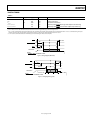
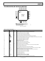
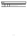
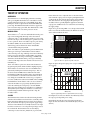
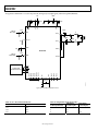
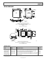
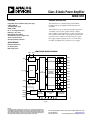
ADAU1592
48
47
46
45
44
43
42
41
40
39
38
37
PGND
PGND
PVDD
PVDD
PVDD
PVDD
PVDD
PVDD
PVDD
PVDD
PGND
PGND
PIN CONFIGURATION AND FUNCTION DESCRIPTIONS
PIN 1
INDICATOR
ADAU1592
TOP VIEW
(Not to Scale)
36
35
34
33
32
31
30
29
28
27
26
25
OUTR–
OUTR–
OUTR–
OUTR+
OUTR+
OUTR+
TEST13
TEST12
AINR
AINL
TEST9
TEST8
NOTES
1. EPAD NOT SHOWN AND INTERNALLY CONNECTED TO
PGND, DGND, AND AGND FOR TQFP-48.
2. EPAD NOT SHOWN AND INTERNALLY CONNECTED TO
PGND AND DGND FOR LFCSP-48.
06749-004
PGA1
PGA0
MUTE
STDN
XTI
XTO
DGND
DVDD
AVDD
AGND
VREF
SLC_TH
13
14
15
16
17
18
19
20
21
22
23
24
OUTL– 1
OUTL– 2
OUTL– 3
OUTL+ 4
OUTL+ 5
OUTL+ 6
TEST1 7
TEST0 8
ERR 9
OTW 10
MO/ST 11
TEST3 12
Figure 4. Pin Configuration
Table 8. Pin Function Descriptions
Pin Number
1, 2, 3
4, 5, 6
7
8
9
10
11
12
13
14
15
16
17
18
19
20
21
22
23
24
25
26
27
28
29
30
31, 32, 33
Mnemonic
OUTL−
OUTL+
TEST1
TEST0
ERR
OTW
MO/ST
TEST3
PGA1
PGA0
MUTE
STDN
XTI
XTO
DGND
DVDD
AVDD
AGND
VREF
SLC_TH
TEST8
TEST9
AINL
AINR
TEST12
TEST13
OUTR+
Type 1
O
O
I
I
O
O
I
I
I
I
I
I
I
O
P
P
P
P
I
I
I
I
I
I
I
I
O
Description
Output of High Power Transistors, Left Channel Negative Polarity.
Output of High Power Transistors, Left Channel Positive Polarity.
Reserved for Internal Use. Connect to DGND.
Reserved for Internal Use. Connect to DGND.
Error Indicator (Active Low, Open-Drain Output).
Overtemperature Warning Indicator (Active Low, Open-Drain Output).
Mono/Stereo Mode Setting Pin for Stereo. Connect to DGND (for mono mode, connect to DVDD).
Reserved for Internal Use. Connect to DVDD.
Programmable Gain Amplifier Select, MSB.
Programmable Gain Amplifier Select, LSB.
Mute (Active Low Input).
Shutdown/Reset Input (Active Low Input).
Quartz Crystal Connection/External Clock Input.
Quartz Crystal Connection/Clock Output.
Digital Ground for Digital Circuitry. Internally connected to exposed pad (ePAD).
Positive Supply for Digital Circuitry.
Positive Supply for Analog Circuitry. (Can be tied to DVDD.)
Analog Ground for Analog Circuitry. (See the notes in Figure 4 for connection to ePAD.)
AVDD/2 Voltage Reference Connection for External Filter.
Slicer Threshold Adjust. (Connect to AGND via a resistor for slicer operation.)
Reserved for Internal Use. Connect to DGND.
Reserved for Internal Use. Connect to DGND.
Analog Input Left Channel.
Analog Input Right Channel.
Reserved for Internal Use. Connect to DGND.
Reserved for Internal Use. Connect to DGND.
Output of High Power Transistors, Right Channel Positive Polarity.
Rev. A | Page 7 of 24