1
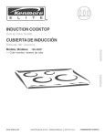
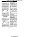
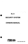
Distributed by
Any reference to Raytheon or
RTN in this manual should be
interpreted as Raymarine.
The names Raytheon and RTN
are owned by the
Raytheon Company.
TOP EDGE BLEED
MASK FOR
2 COLOUR
SEATALK
LOGO
ST 30
DEPTH
Operation and
Installation
TOP EDGE BLEED
MASK FOR
2 COLOUR
SEATALK
LOGO
Nautech Limited, Anchorage Park, Portsmouth
P03 5TD, England
Telephone (0705) 693611. Fax (0705) 694642
ST30 Depth Operation and Installation Handbook
s
tre
Me
W
LO
AL
SH
EP
DE
UM
IM
MIN
ET
FS
OF
PL
DIS
AY
H
PT
DE
TM
Autohelm and SeaTalk are registered Trade Marks of Nautech Limited
Autohelms policy of continuous improvement and updating may change product specifications
without prior notice
Copyright Nautech 1992
ST30 Depth Operation and Installation Handbook
Package Contents
The following items are included in the ST30 Depth package:
1.
ST30 Depth instrument
2.
Fixing studs (2 off)
3.
Thumb nuts (2 off)
4.
Fitting template
5.
1m power cable
6.
Depth transducer (through hull) with 10m cable and 1/8in spade
connectors
7.
Instrument cover
8.
Operation and installation handbook
9.
Daisy-chain cable
1
2
3
SHALLOW
DEEP
MINIMUM
OFFSET
6
DISPLAY
DEPTH
TM
ST30 INSTRUMENT
MOUNTING TEMPLATE
7
TM
4
2-HOLES
DRILL 5mm
( .197in ) DIA
SeaTalk
1-HOLE
DRILL 60.3mm
( 2,3/8in ) DIA
SeaTalk
TM
ST30
5
8
9
DEPTH
Operation and
Installation
SeaTalk
SeaTalk
D624
ST30 Depth Operation and Installation Handbook
3
Contents
Introduction ....................................................................... 4
Chapter 1: Control Head Installation ................................... 5
1.1 Siting ............................................................................. 5
1.2 Mounting procedure ........................................................ 6
1.3 Power supply (Stand-alone operation) ............................... 7
1.4 Power supply (SeaTalk system) ........................................ 7
1.5 Connection to adjacent ST30 Instruments ......................... 8
Chapter 2: Transducer Installation ...................................... 9
2.1 Connection to instrument ................................................. 9
2.2 Transducer type ............................................................. 9
2.3 Installation .................................................................... 10
Chapter 3: Fault Finding ................................................... 12
Chapter 4: Maintenance ................................................... 13
4.1 Instrument .................................................................... 13
4.2 Transducer ................................................................... 13
4.3 Cabling ........................................................................ 13
4.4 Advice .......................................................................... 13
Chapter 5: Operation ....................................................... 14
5.1 Display Key .................................................................. 14
5.2 Light Key ...................................................................... 16
5.3 Alarms ......................................................................... 16
Loss of signal ............................................................... 16
Chapter 6: Calibration ..................................................... 17
6.1 Entry to calibration ........................................................ 17
6.2 Depth units selection ..................................................... 17
6.3 Alarms and Offset ......................................................... 18
Shallow alarm ............................................................... 18
Deep alarm .................................................................. 19
Offset .......................................................................... 20
Exit calibration .............................................................. 21
6.4 Calibration Lock/Unlock ................................................ 22
Return to normal display mode ...................................... 23
6.5 Master/Repeater display ............................................... 23
Return to normal display mode ...................................... 25
Chapter 7: General Specification ...................................... 26
ST30 Depth Operation and Installation Handbook
4
Introduction
Designed for above or below deck installation, the ST30 Depth can be
used as a stand-alone master instrument or be set up to repeat
information from the SeaTalk bus.
The ST30 Depth will display the following information:
• Water depth
• Shallow alarm
• Deep alarm
• Keel/Waterline offset
• Minimum depth
• Illumination level
s
tre
Me
L
AL
SH
OW
EP
DE
UM
IM
MIN
ET
FS
OF
Y
LA
SP
DI
H
PT
DE
TM
D625
5
Chapter 1: Control Head Installation
Chapter 1: Control Head Installation
42mm
(1.65in)
110mm (4.33in)
56mm (2.20in)
SHALLOW
DEEP
MINIMUM
OFFSET
DISPLAY
Autohelm
88mm (3.46in)
24mm (1.0in)
DEPTH
D626
1.1 Siting
The ST30 Depth instrument may be installed above or below deck where it
is:
• easily readable by the helmsman (normally viewed at eye level)
• protected from physical damage
• at least 230mm (9in) from a compass
• at least 500mm (20in) from radio receiving equipment
• accessible from behind for ease of installation and cable running
Note: To prevent the build-up of moisture the instrument breathes through
the back cover. The instrument must, therefore, be mounted where the
back cover is protected from direct water.
The case is fitted with a foam gasket to form a water tight seal between
the instrument and the installation face.
ST30 Depth Operation and Installation Handbook
6
1.2 Mounting procedure
3
6
5
2
4
1
D627
1 Instrument 2 Fixing studs 3 Thumb nuts 4 Sealing gasket
5 Power supply cable 6 Transducer cable
1.
Make sure the surface to which the instrument (1) is to be mounted is
smooth and flat.
2.
Use the template (supplied) to mark the centres for the fixing studs (2)
and the instrument connector boss.
Note: To allow protective covers to be fitted, adjacent instruments
should be sited not less than 6mm (0.24in) from each other (116mm
centre to centre min.).
3.
Drill two 5mm (0.2in) diameter holes for the fixing studs (2).
4.
Using a 60mm (2 3/8in) diameter cutter, drill a location hole for the
instrument connector boss.
5.
Connect the power supply and transducer cables to the back of the
instrument (1). (See relevant installation sections)
6.
Screw the two fixing studs (2) into the back cover of the instrument
(1).
7.
Install the instrument (1) and secure with the thumb nuts (3) provided.
7
Chapter 1: Control Head Installation
1.3 Power supply (Stand-alone operation)
Caution: The ST30 Depth must only be connected to a 12V supply.
+
+
SEATALK
DE
PT
H
+
+
5A
+
Red
12V Supply
Screen
–
D627a
For stand-alone operation, use the 1m cable supplied with the instrument.
1.
Connect the moulded power plug to either SeaTalk connection on the
rear of the instrument. Run the free end back to the vesselÕs
distribution panel.
2.
Cut the power cable to length and connect the red wire to the positive
12V terminal and the screen to 0V. Protect with a 5A circuit breaker
or fuse.
1.4 Power supply (SeaTalk system)
If the ST30 Depth is to be connected to a SeaTalk system, use a Standard
SeaTalk Extension or Interface cable.
Autohelm
Autohelm
Autohelm
Power
Extension Cable
D628
8
ST30 Depth Operation and Installation Handbook
1.5 Connection to adjacent ST30 instruments
The ST30 Depth is supplied with a daisy-chain cable that allows adjacent
ST30 instruments to be linked together. The daisy-chain cable supplies
power to adjacent instruments and allows data to be transmitted and
received via the SeaTalk bus.
The daisy-chain cable plugs into one of the SeaTalk ports on the back
cover. Incorrect orientation is not possible as the ports and plugs are
matched.
9
Chapter 2: Transducer Installation
Chapter 2: Transducer Installation
2.1 Connection to instrument
The ST30 Depth transducer is supplied with 10m (32.5ft) of cable. This
cable plugs directly into the back of the instrument.
+
+
SEATALK
DE
PT
H
+
+
D629
2.2 Transducer type
The ST30 Depth system is supplied (as standard) with a plastic through
hull transducer. This is suitable for use with Glass Reinforced Plastic
(GRP), Steel and Aluminium hulls.
Wooden hull and transom mount installations require a different type of
transducer. Please refer to the following table for details.
Hull material or
location
Transducer
GRP, Steel, Aluminium Standard through hull plastic
Wood
Bronze through hull (Z118)
GRP, Steel, Aluminium Retractable through hull
(Z120)
In hull
In hull puck (Z117)
Caution: Plastic through hull transducers must not be used on vessels
with wooden hulls.
ST30 Depth Operation and Installation Handbook
10
2.3 Installation
All depth transducers are supplied with detailed installation and
maintenance instructions. These instructions, together with the following
notes, should be read thoroughly before attempting to install the
transducer.
10° Max
D630
1.
The ST30 Depth transducer must be within 10° of the vertical,
forward, aft and athwart ships and within the shaded clear flow areas
as shown.
D587
11
Chapter 2: Transducer Installation
2.
Run the transducer cable back to the instrument. Avoid fluorescent
lights, engines, radio transmitting equipment and the speed
transducer cable. The transducer cable should also be kept clear of
bilge's, where possible, and be secured at regular intervals.
Note: The transducer cable must not be shortened. Shortening
of this cable will affect the performance of the unit. For further
information, please contact Autohelm or an authorised agent.
If the bronze through hull (Z118), in hull puck (Z117) or retractable depth
(Z120) transducers are to be used, the following modification must be
carried out to the transducer lead.
1.
Using a pair of wire cutters, remove the moulded plug from the end
of cable.
2.
Strip the outer cable back 38mm (1.5in).
3.
Using a pair of cable strippers, remove 10mm (3/8in) of insulation
from each wire.
4.
Using a suitable crimping tool, attach a 1/8in spade connector
(supplied) to each of the wires.
5.
Connect the wires to the instrument in accordance with the following
table.
Transducer type
Colour coding (cable to unit)
Bronze through hull
(Z118)
Blue Ð red terminal
Black and screen Ð white
terminal
In-hull puck (Z117)
As above
Retractable depth
(Z120)
As above
ST30 Depth Operation and Installation Handbook
12
Chapter 3: Fault Finding
All Autohelm products are, prior to packing and shipping, subject to
comprehensive test and quality assurance programmes. However, if a
fault arises with the ST30 Depth, the following table will help to identify the
probable cause and provide the most likely cure.
Fault
Cause
Action
Instrument display
blank
No supply to
instrument
Check supply
Check cabling and
security of connectors
Check circuit
breaker/fuse
Return ST30 Depth for
repair
No depth information
Aereated water, boat
wakes or propeller
wash
Depth reading will
return to normal once
clear of disturbed
water
Feet/metres display
flashes continuously
Transducer cable or
connector fault
Check cabling and
security of transducer
connector
No exchange of
information between
SeaTalk instruments
SeaTalk cabling or
connector problem
Check security of
SeaTalk connectors
Remove instruments one
by one to isolate
faulty unit
Failure of a group of Cabling or connector
instruments in a chain problem
Check the security of
the connectors between
functioning and
non-functioning
instruments
Unable to enter
calibration
Refer to Calibration
lock/
unlock section
Calibration locked
Note: After installation, poor performance may be experienced if the
surface of the depth transducer has not been 'wetted'. Wetting can take
up to 24 hours under normal conditions. The transducer can be 'wetted'
prior to launch by applying a mild detergent to the external face.
13
Chapter 4: Maintenance
Chapter 4: Maintenance
4.1 Instrument
Atmospheric conditions may cause condensation to appear on the
instrument window. This will not harm the instrument and can be cleared
by increasing the illumination setting to level 3.
Chemical and abrasive materials must not be used to clean the
ST30 Depth instrument; if the instrument is dirty, clean with a soft, damp
cloth.
4.2 Transducer
Refer to the Installation and Maintenance instructions supplied with the
transducer.
4.3 Cabling
Examine all cables for chafing or damage to the outer shield and, where
necessary, replace and re-secure.
4.4 Advice
For advice, or further information regarding installation of this product,
please contact the Autohelm Product Support Department or your own
National Distributor.
ST30 Depth Operation and Installation Handbook
14
Chapter 5: Operation
The ST30 Depth leaves the factory set to:
• display depth in feet
• with the deep and shallow alarms switched off
• in master mode
These settings can be changed in calibration (see section 6.1).
When the ST30 Depth is switched on, the instrument will display current
water depth in the units set up in calibration.
SHALLOW
Feet
DEEP
MINIMUM
D643
OFFSET
Note: The trend arrows ▲ decreasing ▼ increasing, shown in the above
display, indicate whether the trend is towards deep or shallow water.
5.1 Display Key
Each press of Display cycles the following menu:
• Shallow Alarm Setting
• Deep Alarm Setting
• Minimum Depth
• Offset (Keel or Waterline)
A further press of Display will return the unit to current depth. The
display always returns to current depth after 8 seconds.
SHALLOW
Feet
DEEP
MINIMUM
OFFSET
TM
DEPTH
D644
DISPLAY
15
Chapter 5: Operation
SHALLOW
Feet
DEEP
MINIMUM
OFFSET
DEPTH
SHALLOW
D645
DISPLAY
Feet
DEEP
MINIMUM
OFFSET
DEPTH
TM
D646
DISPLAY
Note: The 'Minimum' depth display may be reset by pressing
second.
SHALLOW
Feet
DEEP
MINIMUM
OFFSET
D647
DISPLAY
TM
DEPTH
for 1
ST30 Depth Operation and Installation Handbook
16
5.2 Light Key
Controls the level of instrument illumination. There are 3 levels, with
level 3 the brightest.
SHALLOW
DEEP
MINIMUM
OFFSET
TM
DEPTH
D648
DISPLAY
The display returns to correct depth after 8 seconds.
Note: When the ST30 Depth is used in a SeaTalk system, illumination may
be adjusted from any instrument.
5.3 Alarms
The ST30 Depth is equipped with visual and audible shallow and deep
water alarms.
Both of these alarms are set in calibration (see section 6.3).
Any button press will silence the 'Shallow' alarm. However, the 'Shallow'
indicator will continue to flash until the depth exceeds the alarm value.
The 'Deep' alarm sounds when the 'Deep' setting is crossed either when
going from shallow to deep or deep to shallow waters. Any button press
will silence the alarm.
Loss of Signal
The 'feet or metres' legend flashes whenever the depth signal is lost.
SHALLOW
DEEP
Metres
MINIMUM
D657
OFFSET
Chapter 6: Calibralicn
Chapter 6: Calibration
6.1 Entry to calibration
The ST30 Depth can be programmed to display depth information in feet
or metres. To enter calibration, press and hold Diiy and %f After 2
seconds the display till show CM.
Each press of Display will cycle the unitthrough the calibration menu.
6.2 Depth units selection
1.
Cycle Display until the display shows feet or meties.
2.
Select feet or metres as required using A.
6.3 Alarms and Offset
Shallow alarm
1.
Cycle Display until the ‘Shallod alarm is displayed.
2.
Press A or V to set the required depth.
fr
3.
17
Shallow Alarm is enabled by pressing %T When the alarm is on the
‘Alarm’ legend will be displayed.
Chapter 6: Calibration
19
;: ,: iiiii,ii,,i,,,ii,ii,
,,i, ,,i , , ,.i, , , , ,i,, ,i,,,, ,i,,,
iiii
Deep alarm
1.
Cycle Display until ‘Deep’ alarm is displayed.
2.
Press A or V to set the required depth
-
i
3.
DEPTI
The ‘Deep’ alarm is enabled by pressing 9. When the alarm is on the
‘Alarm’ legend will be displayed.
I
-
DEPTH
ST30 Depth Operation and hstallalion Handbook
20
Offset
The instrument measures the water depth below the transducer. To
display water depth below the keel or to the surface an offset must be set
up. A negative offset is used to reduce the displayed value and give depth
below the keel, a positive offset will give water depth to the surface.
1.
Press Display until
2.
offd is selected.
DEPTH
Press A or V until the rewired offset is
I
I
-
I
1
DEPTH
Exii calibration
To exii calibration and return to depth mode, press and hdd Display
and for a 2 seconds.
111111
DEPTH
6.4 Calibration Lock/Unlock
The lock/unlock feature removes the risk of accidentaliy changing the set
calibration values.
For securii, the calibrabon lock/unlock feature is accessed by an
extended hold down of the 4 and Dfspfay keys as follows:
1.
Press and hold Diiplay and %T for 14 seconds until CAL is displayed
for tie second time.
2.
Press A and V momentarily.
f,
I
23
-6:C
3.
Calibrabon lock/unlock is switched on or off usin&? A
CO = Calibration locked i.e. no access
Cl = Calibration unlocked i.e. normal access.
Return to normal display mode
Press and hold Display and a After 2 seconds the display returns to
depth mode.
6.5 Master/Repeater display
As It leaves the factory the ST30 Dapth is set
to operate in Master mode.
In this mode the inshument is connected to a depm transducer and
bansmits depth informah onto the SeaTalk bus. The ST30 Depth can be
set as a Repeater, repeating depth infomutitx already on the SeaTalk
bus. Repeater mode is set as follows:
STSODephOperaWnmdlnstal&limrtaRationHandbook
1 . PressandholdDispbyand~uuntilthedisplayshowsaUandatwa
figure number.
2.
Press Display to show the current operating mode.
3.
Press A to change mode.
r0 = Master mode
rl = Repeater mode
Note: When the ST30 Depi31 is set in Repeater mode access to
Calibration is inhibited.
Chapter6:Calibra6on
25
Return to normal display mode
Press and hold Display and ?# After 2 seconds UE display returns to
depth mode.
ST30 Depth Operation and Installation Handbook
26
Chapter 7: General Specification
Power supply:
Power consumption:
10 to 16V
60mA (without illumination)
100mA (illuminated)
Transmitted power (RMS):
50W
Operating frequency:
200kHz
Temperature range:
0 to 70 deg° C
Shallow alarm:
1 to 10m (0.1 increments)
3 to 33ft (1ft increments)
Deep alarm:
3 to 120m (1m increments)
10 to 400ft (10ft increments)
Offset:
–4 to +4m (0.1 increments)
–9.9 to +9.9ft (0.1 increments)
Minimum depth function:
Reset on power-up
Units:
Software programmable selection
in metres (m) or feet (ft) – stored
in EPROM
Calibration lock/unlock:
Software programmable
Repeater capability:
Software programmable
81002-1
TOP EDGE BLEED
MASK FOR
2 COLOUR
SEATALK
LOGO
Nautech Limited, Anchorage Park, Portsmouth
P03 5TD, England
Telephone (0705) 693611. Fax (0705) 694642
TOP EDGE BLEED
MASK FOR
2 COLOUR
SEATALK
LOGO
Nautech Limited, Anchorage Park, Portsmouth
P03 5TD, England
Telephone (0705) 693611. Fax (0705) 694642