1
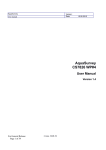
 Dolby Media Meter 2
User’s Manual
®
Issue 3
Part Number 9110860
Dolby Laboratories, Inc.
Corporate Headquarters
Dolby Laboratories, Inc.
100 Potrero Avenue
San Francisco, CA 94103‐4813 USA
Telephone 415‐558‐0200
Fax 415‐863‐1373
www.dolby.com
European Headquarters
Dolby Laboratories, Inc.
Wootton Bassett
Wiltshire SN4 8QJ England
Telephone 44‐1793‐842100
Fax 44‐1793‐842101
DISCLAIMER OF WARRANTIES:
EQUIPMENT MANUFACTURED BY DOLBY LABORATORIES IS WARRANTED AGAINST DEFECTS IN MATERIALS AND WORKMANSHIP FOR A PERIOD OF ONE YEAR FROM THE DATE OF PURCHASE. THERE ARE NO OTHER EXPRESS OR IMPLIED WARRANTIES AND NO WARRANTY OF MERCHANTABILITY OR FITNESS FOR A PARTICULAR PURPOSE, OR OF NONINFRINGEMENT OF THIRD‐PARTY RIGHTS (INCLUDING, BUT NOT LIMITED TO, COPYRIGHT AND PATENT RIGHTS).
LIMITATION OF LIABILITY: IT IS UNDERSTOOD AND AGREED THAT DOLBY LABORATORIES’ LIABILITY, WHETHER IN CONTRACT, IN TORT, UNDER ANY WARRANTY, IN NEGLIGENCE, OR OTHERWISE, SHALL NOT EXCEED THE COST OF REPAIR OR REPLACEMENT OF THE DEFECTIVE COMPONENTS OR ACCUSED INFRINGING DEVICES, AND UNDER NO CIRCUMSTANCES SHALL DOLBY LABORATORIES BE LIABLE FOR INCIDENTAL, SPECIAL, DIRECT, INDIRECT, OR CONSEQUENTIAL DAMAGES (INCLUDING, BUT NOT LIMITED TO, DAMAGE TO SOFTWARE OR RECORDED AUDIO OR VISUAL MATERIAL), COST OF DEFENSE, OR LOSS OF USE, REVENUE, OR PROFIT, EVEN IF DOLBY LABORATORIES OR ITS AGENTS HAVE BEEN ADVISED, ORALLY OR IN WRITING, OF THE POSSIBILITY OF SUCH DAMAGES.
. Dolby and the double‐D symbol are registered trademarks of Dolby Laboratories. Dialogue Intelligence is a trademark of Dolby Laboratories. All other trademarks remain the property of their respective owners.
© 2012 Dolby Laboratories. All rights reserved.
ii
Part Number 9110860
Issue 3
S12/23665/25266
Dolby® Media Meter 2 User’s Manual
Table of Contents
Chapter 1 Dolby Media Meter Overview ......................................................................................1
Chapter 2 Installing Dolby Media Meter
2.1 Installing Dolby Media Meter 2 on a Mac............................................................................3
2.2 Installing Dolby Media Meter on a PC ................................................................................3
2.3 Using the Dolby Media Producer iLok ................................................................................4
Chapter 3 Measuring Loudness
3.1 Measuring Equivalent Loudness ........................................................................................5
3.2 Measurement Modes: Short Term vs Infinite......................................................................6
3.2.1 Infinite Mode ............................................................................................................6
3.2.2 Short-Term Mode.....................................................................................................6
3.3 Measuring with the Stand-Alone Product ...........................................................................7
3.4 Measuring with the Plug-Ins ...............................................................................................9
3.5 Measuring with the AudioSuite Plug-In.............................................................................11
3.6 File-Naming Conventions That Ensure Automatic File Selection .....................................12
Chapter 4 Configuring the Meter
4.1
4.2
4.3
4.4
4.5
4.6
4.7
4.8
Measurement Algorithm ...................................................................................................17
Short-Term Window..........................................................................................................17
Peak Measurement Type .................................................................................................17
Level Meters .....................................................................................................................17
Limiter ...............................................................................................................................17
Measurements Displayed .................................................................................................17
Graphing ...........................................................................................................................17
Warnings ..........................................................................................................................18
Chapter 5 Understanding the Log and the Graph
5.1 Reading the Log ...............................................................................................................19
5.2 Viewing the Graph ............................................................................................................20
Appendix A Dolby Loudness Product Comparison
A.1
A.2
A.3
A.4
Measuring a Single Center Channel in a 5.1 Program .....................................................21
Measuring a Stereo Program ...........................................................................................22
Measuring with Dialogue Intelligence On and Speech Absent .........................................22
Measuring a 5.1 Program .................................................................................................22
Dolby® Media Meter 2 User’s Manual
iii
List of Figures
Figure 1-1
Figure 3-1
Figure 3-2
Figure 3-3
Figure 3-4
Figure 3-5
Figure 3-6
Figure 4-1
Figure 4-2
Figure 4-3
Figure 5-1
Figure 5-2
Figure 5-3
Stand-Alone Meter Measuring a Set of Source Files ............................................................ 1
Measurement Algorithm Choices in the Settings Window..................................................... 5
Measurement Pane Showing Tenths .................................................................................... 6
Short-Term Window Length Setting ...................................................................................... 7
Stand-Alone Meter Measuring an Encoded File.................................................................... 8
Dolby TrueHD Presentation Selector .................................................................................... 9
Dolby Media Meter 2 RTAS Plug-In Window....................................................................... 10
Application Settings Button.................................................................................................. 15
Plug-In Settings Button........................................................................................................ 15
Settings Window.................................................................................................................. 16
Sample Log File Beginning.................................................................................................. 19
Sample Log File End ........................................................................................................... 19
Sample Graph ..................................................................................................................... 20
Dolby® Media Meter 2 User’s Manual
iv
Chapter 1
Dolby Media Meter Overview
Welcome to the Dolby® Media Meter 2. Dolby Media Meter 2 is a software tool for measuring loudness in programming. It’s an ideal tool for program creation and quality control, and perfect for optimizing broadcast and disc media. Dolby Media Meter 2 runs as an Apple® Macintosh® or Microsoft® Windows® stand‐alone application and as Avid® Pro Tools® AudioSuite, Real‐Time AudioSuite (RTAS®), Steinberg Virtual Studio Technology (VST), and Apple Audio Unit (AU) plug‐ins.
Figure 1‐1
Figure 1-1
Stand-Alone Meter Measuring a Set of Source Files
Dolby® Media Meter 2 User’s Manual
1
Dolby Media Meter Overview
Questions or Feedback
If you have questions or comments about this document, please contact technical publications.
If you have technical questions about this product/technology, please contact technical
support.
2
Dolby® Media Meter 2 User’s Manual
Chapter 2
Installing Dolby Media Meter
The process of installing Dolby® Media Meter 2 consists of two required steps:
2.1
1.
Installing the Dolby Media Meter 2 software 2.
Activating the iLok™ Installing Dolby Media Meter 2 on a Mac
To install Dolby Media Meter 2 on a Mac®:
1.
Insert the CD into the optical drive. The CD opens automatically.
2.
Read the introduction, then click Continue.
3.
Read the license agreement. You may choose to print and save it for your records. Click Continue to proceed.
4.
Click Agree to accept the license agreement and proceed with installation.
5.
Select a destination drive. Click Continue….
Note:
Dolby Media Meter 2 is automatically installed into the Applications/Dolby Media
Producer folder on the Macintosh® hard drive. You may move it after installation.
When the system has completed the installation, it automatically opens your Web browser to www.dolbysupport.com. The site allows you to open an account, if you have not already done so, and to register your product. Registering your product allows you to receive technical support and notice of future upgrades.
6.
2.2
When you are ready, close the technical support window and click Close on the installer to complete the installation.
Installing Dolby Media Meter on a PC
To install Dolby Media Meter 2 on a PC:
1.
Insert the CD into the optical drive. The CD opens automatically.
2.
Read the introduction, then click Next.
3.
Click I accept the terms in the license agreement. Click Next to proceed.
The system automatically installs Dolby Media Meter 2 in C:\Program Files\Dolby Media
Meter\Dolby Media Meter, then places icons on the desktop and under the Start menu. Note:
After installing Dolby Media Meter 2, you must restart your PC before the program can be used. Dolby® Media Meter 2 User’s Manual
3
Installing Dolby Media Meter
2.3
Using the Dolby Media Producer iLok
One iLok USB smart key containing a unique license is packaged along with your Dolby Media Meter CD. The license stored on the iLok smart key authorizes your system to use the application. Insert the iLok into an available USB port before opening the application. The iLok key must remain in the USB port while the software is in use.
Caution: Do not lose your iLok. Keep it as safe and secure as you would any other valuable piece of equipment. Losing the iLok is the same as losing the entire product.
The iLok website allows to you to manage the licenses for all your iLok‐protected applications in one place. Registration is simple. To register your license:
1.
Go to ilok.com.
2.
Follow the directions to sign up for a free account.
3.
Download and install the iLok client software.
4.
Log in to your account.
5.
Synchronize your iLok with your account.
6.
View the licenses on your newly registered iLok.
7.
Add and edit the name of the iLok for differentiation if you own multiple iLoks.
Consider Subscribing to iLok Zero Downtime Coverage
The iLok Zero DownTime program enables iLok owners to immediately replace licenses in case an iLok is broken, lost, or stolen. See ilok.com for program details and restrictions.
4
Dolby® Media Meter 2 User’s Manual
Chapter 3
Measuring Loudness
3.1
Measuring Equivalent Loudness
Differences in audio levels between programs and channels or between programs and commercials are a major annoyance to TV viewers. While obvious to the viewer, these loudness differences have proven difficult to measure with conventional methods and equipment.
For years, the audio industry has quantified the level of its programming using peak program meters (PPM) and volume unit (VU) meters. It is important to note that both were developed and are used to read signal voltages, and therefore make no attempt to measure subjective loudness. Thus, several different voices, adjusted in level so that they all deflect meters to the same mark, may sound somewhat different in level to the listener at home. This problem is often compounded by the rapid response of the meter, which requires all operators to perform their own individual visual integration or averaging of the meter movement itself.
Dolby® Media Meter 2 features Dialogue Intelligence™ technology, adopted from the award‐winning Dolby DP600 Program Optimizer, which automatically detects and then measures loudness only during the presence of speech in an audio track. Enabling Dialogue Intelligence allows the operator to simply quantify all the sections of the program that only contained dialogue and use the ending measurement value for analysis and/or normalization purposes. This value is also commonly used to set the dialogue normalization parameter within Dolby bitstreams.
Dolby Media Meter 2 offers three measurement algorithm choices in the settings window, as shown in Figure 3‐1:
•
ITU‐R BS.1770‐2
•
ITU‐R BS.1770‐1
•
Leq(A)
Figure 3‐1
Figure 3-1
Measurement Algorithm Choices in the Settings Window
EBU R128 measurements, including integrated loudness, short‐term loudness, and loudness range, are available when ITU BS.1770‐2 is selected. Dialogue Intelligence can be used with either ITU‐R BS.1770‐1 or Leq(A). You can measure the loudness of Dolby Digital, Dolby Digital Plus, Dolby TrueHD, Dolby E, and PCM files. Dolby® Media Meter 2 User’s Manual
5
Measuring Loudness
Choosing a Measurement Precision
You can change the display to show measurements in tenths or integers (units). To make this change, right‐click the measurement pane shown in Figure 3‐2, then choose Units or Tenths from the display context menu. The current setting is marked.
Figure 3‐2
Figure 3-2
3.2
Measurement Pane Showing Tenths
Measurement Modes: Short Term vs Infinite
The Dolby Media Meter 2 has two modes relating to the measurement period itself: Infinite mode and Short‐Term mode. The following sections describe their behavior.
3.2.1
Infinite Mode
Infinite mode1 is typically used when it is possible to measure the entire duration of the program (for example, all 30 seconds of a commercial or a complete two‐hour movie). Infinite mode provides the most accurate measurement, as it is able to average loudness over the complete program length. This mode is most often used in ingest, quality control (QC), and postproduction applications where audio metadata is being authored and levels can, in most cases, be controlled and adjusted.
It is also possible to use Infinite mode to measure shorter individual sections of a program rather than the entire duration. This method may allow the operator to find a measurement value much more quickly. In this case, however, the operator must ensure that the loudness levels of the sections being measured are representative of the entire program. 3.2.2
Short-Term Mode
Short‐Term mode displays the measured value for the previous few seconds as a “sliding window” type of function. Using Dialogue Intelligence, for example, the first measurement value is for the time between 0 and 10 seconds, the next between 1 and 11 seconds, next between 2 and 12 seconds, and so forth. Using EBU R128, the measurements are for three seconds, rather than ten.
As the Short‐Term mode measures only the immediately preceding ten seconds of program material, the measurement value has the potential to be much more dynamic than the value 1
6
EBU R128 uses the term Integrated instead of Infinite.
Dolby® Media Meter 2 User’s Manual
Measuring with the Stand-Alone Product
provided by Infinite mode measurement for the same content. (Highly processed channels and programming will most likely not exhibit this type of behavior.) The benefit of measuring in Short‐Term mode is that the operator can see short‐term variations in loudness level (or short‐term variations in dialogue level when Dialogue Intelligence is enabled) within a program. Many skilled audio operators prefer to use the Short‐Term mode measurement, as they find the information on near‐term dynamics to be very useful when mixing or producing a program, and they are capable of managing overall program loudness by reading the short‐term measure.
Short‐Term mode is also very useful for measuring and logging the dynamic loudness history of a given program during the QC or postproduction process, or in a particular television service or channel in a cable headend facility.
Choosing a Short-Term Window Length
Some standards allow a choice of short‐term window length, either three or ten seconds. Dolby Media Meter includes a setting for this choice, as shown in Figure 3‐3.
Figure 3‐3
Figure 3-3
3.3
Short-Term Window Length Setting
Measuring with the Stand-Alone Product
The stand‐alone Dolby Media Meter 2 application measures source and encoded files. The software analyzes the input, then displays the measured results for use in determining the proper dialnorm metadata value to use during encoding. This is useful for DVD and Blu‐ray Disc™ postproduction, broadcast facilities, video on demand (VOD), movie download services, and video games. Before you begin to measure, check the default values on the Dolby Media Meter settings screen discussed in Chapter 4.
Dolby® Media Meter 2 User’s Manual
7
Measuring Loudness
Figure 3‐4
Figure 3-4
Stand-Alone Meter Measuring an Encoded File
To measure the loudness of an encoded file or a source file set:
1.
Click to choose either Source files or an Encoded file.
2.
Identify the input file or files, either by browsing the network, or by typing a file name and location into the name field.
As in other Dolby Media Producer applications, the file selector is intelligent. When you double‐click a source file, Dolby Media Meter 2 recognizes and selects the entire set when the set follows the naming conventions described in Section 3.6.
3.
Click Enable if you want to create a log file of this measurement. Review the default log file name and location, and make any required modifications.
By default, the Dolby Media Meter 2 names log files input file name-LoudnessEstimation.csv and saves the file in the directory where the input files are stored. See Section 5.1 for more details about the log function. 4.
8
Click Specify Range to measure only part of the selected file.
Dolby® Media Meter 2 User’s Manual
Measuring with the Plug-Ins
Unless a range is specified here, Dolby Media Meter 2 measures the entire file. If timecode is embedded in the files, the meter will default to timecode; if timecode is not present, the the meter will default to real time. Highlight either or both the beginning and end fields, and type new values to change them. Dolby Media Meter 2 supports all common video frame rates, as well as frames, seconds, and samples, in addition to real‐time measurement.
5.
Click Measure to start processing.
Dolby Media Meter 2 displays a percentage‐complete tally and progress bar during processing. During measurement, the Measure button changes to Cancel.
When measuring encoded files, Dolby Media Meter 2 can display up to four different measurement types simultaneously, as shown in Figure 3‐4. Choose the from the nine available options by right‐clicking in a measurement box. When measurement finishes, you can read the log (as described in Section 5.1) or view a graph (as described in Section 5.2).
Additional Selectors for Dolby TrueHD and Dolby E
When a Dolby TrueHD file is chosen, Dolby Media Meter 2 displays the additional selector shown in Figure 3‐5, allowing you to choose which presentation Dolby Media Meter 2 should measure. The selector lists only independent and downmixed presentations. Copies are not displayed, as their value would be identical to the presentation of which they were a copy.
Figure 3‐5
Figure 3-5
Note:
Dolby TrueHD Presentation Selector
Large Dolby TrueHD files may take a little longer to open than other file types because Media Meter 2 must examine the entire file before beginning to measure it.
When a Dolby E file containing more than one program is selected, Dolby Media Meter 2 allows you to choose which program Dolby Media Meter 2 should measure. The selector lists only the programs that exist in the selected Dolby E stream.
In both cases, measurement does not proceed until you have indicated a choice.
3.4
Measuring with the Plug-Ins
As a Pro Tools® RTAS® or VST plug‐in, Dolby Media Meter 2 measures loudness in real time, letting you track levels during the mixing process to aid in meeting network delivery requirements. Dolby Media Meter 2 can simultaneously display up to seven of the nine possible measurements described in Section 4.6. Choose a measurement to display by right‐clicking in a measurement box and choosing from the context menu. Figure 3‐6 shows a plug‐in example.
Dolby® Media Meter 2 User’s Manual
9
Measuring with the Plug-Ins
Figure 3‐6
Figure 3-6
Dolby Media Meter 2 RTAS Plug-In Window
Dolby® Media Meter 2 User’s Manual
10
Measuring with the AudioSuite Plug-In
Dolby Media Meter 2 RTAS or VST plug‐in insertion is performed on a channel‐by‐channel basis on input channels. On output buses, the meter may be inserted on mono, stereo, or multichannel buses. The number of instances is not limited.
Note:
Pro Tools always inserts both RTAS and AudioSuite plug‐ins as prefader. Measurements will not correctly match the final mixed output if the meter is inserted on the input section of Pro Tools when mix automation is present.
When you measure with the RTAS and VST plug‐ins, Dolby Media Meter 2 does not add to the infinite value while the session is stopped or paused. You can move along the session timeline and add to the infinite average by playing through different sections. Doing so allows you to average over the entire time you work on your session. In addition, the log file will reference the measurement entries with an indication of both the timecode of the part of the session being measured and the time of day the measurement was taken.
When you measure with the RTAS and VST plug‐ins, the graph is displayed in real time, letting you see exactly what is happening. Resetting Measurements
Click Reset All to restart the all measurements. Click Reset Avg to reset only the infinite measurement. Reset the dialogue range and peak measurements by clicking the Reset button beneath the appropriate readout. Clicking View Log displays the log file.
3.5
Measuring with the AudioSuite Plug-In
The Dolby Media Meter 2 AudioSuite plug‐in performs file‐based measurement, ideal for measuring dialnorm values or overall loudness while preparing audio for packaged media formats. Note:
When measuring multichannel input channels, be sure to select the channel routing in the setting window that matches your session.
When measuring with the AudioSuite meter, you can select a section of your session to measure in non real time and press the Process button. To average the measurements of different sections, select a new section of your timeline, and press the Process button again. That section will be averaged into the previous measurement. If you do not wish to average the different sections, simply press the Reset button before pressing the Process button. If you choose to create a log file, the log file will reference the measurement entries with an indication of both the timecode of the part of the session being measured and the time of day the measurement was made. This will allow you to tell which part of your session is represented by the given measurement. The AudioSuite plug‐in can display can simultaneously display up to seven of the nine possible measurements described in Section 4.6. Choose a measurement to display by right‐clicking in a measurement box and choosing from the context menu. Dolby® Media Meter 2 User’s Manual
11
Measuring Loudness
To measure faster than real time in the AudioSuite plug‐in:
Note:
3.6
Remember that Pro Tools always inserts both RTAS and AudioSuite plug‐ins as prefader. Measurements will not correctly match the final mixed output if the meter is inserted on the input section of Pro Tools when mix automation is present.
1.
Click Reset to restart the measurements.
2.
Click Log File to generate and save a log of Dolby Media Meter 2 activity. Review the default file name and location, and make any necessary changes.
3.
Choose the desired measurement types, by right‐clicking in a measurement box and choosing another option from the context menu. File-Naming Conventions That Ensure Automatic File
Selection
Dolby Media Meter 2 automatically selects source file sets that follow these naming rules: 1.
All the channel IDs used are standard. The channel IDs are not case sensitive. 2.
The channel ID is separated before and after with either a period or underscore. 3.
The file names for the channels are identical except for channel ID. 4.
The number of files matches the number of channels selected in the client Channels tab. 5.
The file channel IDs match the channel IDs selected in the client Channels tab. 6.
File names do not contain the ampersand (&) character.
Caution: File names including the ampersand (&) character cannot be processed by the Dolby Media Producer suite.
The following sections provide four examples of file sets that would be automatically selected.
Example 1
This file set uses a period as the separator.
•
ExampleOne.L.wav •
•
•
ExampleOne.R.wav •
•
ExampleOne.Ls.wav ExampleOne.C.wav ExampleOne.LFE.wav ExampleOne.Rs.wav Example 2
This file set uses an underscore as the separator.
12
•
ExampleTwo_L.wav •
ExampleTwo_R.wav Dolby® Media Meter 2 User’s Manual
File-Naming Conventions That Ensure Automatic File Selection
•
ExampleTwo_C.wav •
ExampleTwo_LFE.wav •
ExampleTwo_Ls.wav •
ExampleTwo_Rs.wav Example 3
In this file set, the channel ID is not the last element in the file name. The file set uses a period as the separator.
•
ExampleThree.L.ENG.wav •
ExampleThree.R.ENG.wav •
ExampleThree.C.ENG.wav •
ExampleThree.LF.ENG.wav •
ExampleThree.LS.ENG.wav •
ExampleThree.RS.ENG.wav Example 4
In this file set, the channel ID again is not the last element in the file name. The file set uses an underscore as the separator.
•
ExampleFour_L_ENG.wav •
ExampleFour_R_ENG.wav •
ExampleFour_C_ENG.wav •
ExampleFour_SW_ENG.wav •
ExampleFour_LS_ENG.wav •
ExampleFour_RS_ENG.wav Dolby® Media Meter 2 User’s Manual
13
Chapter 4
Configuring the Meter
Dolby® Media Meter 2 offers you a wide range of choice about what and how you measure. This chapter explains the choices. To configure Dolby Media Meter 2, click the settings icon, which shows three sliders. In the stand‐alone application, it appears in the far bottom left corner, as shown in Figure 4‐1. In the plug‐ins, it is at the left underneath the Dolby logo, as shown in Figure 4‐2.
Figure 4‐1 Figure 4‐2 Figure 4-1 Application Figure 4-2 Plug-In Settings
Settings Button
Button
The system opens the Dolby Media Meter 2 settings window, shown in Figure 4‐3.
Dolby® Media Meter 2 User’s Manual
15
Configuring the Meter
Figure 4‐3
Figure 4-3
16
Settings Window
Dolby® Media Meter 2 User’s Manual
Measurement Algorithm
4.1
Measurement Algorithm
Choose Leq(A), ITU‐R BS.1770‐1, or ITU‐R BS.1770‐2 by clicking a radio button at the top of the settings window. 4.2
Short-Term Window
Choose a length for standards that allow this option (three seconds or ten seconds).
4.3
Peak Measurement Type
You can choose between the default peak measurement type, Sample Peak, and True Peak, which includes peaks that occur in between samples. Note:
4.4
Determining true peaks is calculation intensive. You may notice increased CPU resource use in real‐time applications when you choose True Peak.
Level Meters
All of the real‐time plug‐ins allow you to show level meters similar to those in the Dolby Media Decoder for each channel being measured. 4.5
Limiter
All of the real‐time plug‐ins allow you to apply a peak limiter. Unlike most Dolby Media Meter 2 features, this limiter acts on your tracks. You can set this value from 0 to –51 to aid in preventing your tracks from exceeding the selected peak value, helping you to meet delivery specifications.
4.6
Measurements Displayed
In the stand‐alone application, you can display any four measurements in any order. In the plug‐ins, you can display up to seven in any order. 4.7
Graphing
Dolby Media Meter 2 provides a flexible graphing feature to aid in visualization of the measurements it makes.
Right‐clicking in the graph window opens a contextual menu with commands to: •
Select the measurements to be graphed.
•
Clear the graph display.
•
Latch or unlatch the graph display.
Dolby® Media Meter 2 User’s Manual
17
Configuring the Meter
•
Print the graph display. When printing the graph, the printed version will be only what is currently displayed in the graph. No reading outside the display will be printed.
Resizing the Graph
The graph is the only part of the Dolby Media Meter 2 display that can be resized. To resize it horizontally, drag the bottom right corner of the windowto the right. When unlatched from the plug‐ins, the graph can be resized up to full screen. 4.8
Warnings
Dolby Media Meter 2 allows you to configure seven types of warning:
•
Infinite Dialogue: The Target can be set from 0 to –60. Positive and negative tolerances •
Short Term Dialogue: Both the minimum and maximum warning can range from 0 to are adjustable from 0 to 60. –60. •
Infinite All: The Target can be set from 0 to –60. Positive and negative tolerances are adjustable from 0 to 60.
•
Integrated EBU R128: The Target can be set from 0 to –60. Positive and negative tolerances are adjustable from 0 to 60.
•
Loudness Range EBU R128: The maximum can be adjusted from 0 to –60.
•
Peak Value: The maximum can be adjusted from 0 to –60.
•
Leq(M) Value: The maximum can be adjusted from 72 to 96.
Dolby Media Meter 2 sets generally acceptable default values for all these warnings, which you can adjust as needed.
When a warning is triggered, Dolby Media Meter 2 displays it in two ways:
18
•
Measurement windows change their display color from white to red. •
The graph window shows a vertical line at the point in the timeline when the warning occurred. This line is accompanied by a horizontal line at the bottom of the graph that extends across all the time the error was in effect, and is colored matched to the warning type that occurred.
Dolby® Media Meter 2 User’s Manual
Chapter 5
Understanding the Log and the Graph
Dolby® Media Meter 2 lets you view and save both a graph and log file for each measurement you make.
5.1
Reading the Log
When it processes source or encoded files, Dolby Media Meter 2 creates a log file containing a record of its measurements. The log is created as a comma‐separated values (.csv) file, allowing you to open and save it in TextEdit, Microsoft® Excel®, or any other spreadsheet editor. Figure 5‐1
Figure 5-1
Sample Log File Beginning
As shown in Figure 5‐1, the log file begins with crucial information about the input. It states the name and file location for the input file or files, its audio coding mode, whether Dialogue Intelligence™ is on or off, and the chosen peak count threshold value.
Figure 5‐2
Figure 5-2
Sample Log File End
As shown in Figure 5‐2, the log file ends with the measured loudness, highest peak, and the percentage of speech content for the entire file or file set.
Dolby® Media Meter 2 User’s Manual
19
Understanding the Log and the Graph
In between, the log lists several attributes for each second of real time:
•
Timecode: Indicates the section of the file measured
•
Date: Indicates the calendar date on which the measurement was made
•
Time of day: Indicates the time of day the measurement was made
•
Dialogue present: Indicates the channels that contained dialogue or no dialogue
•
The measurements you chose
•
The warnings you chose
•
Peak (dBFS): Indicates the largest peak value measured in the section
•
Peak count: Indicates the number of peaks in the section that exceeded the peak count threshold value
Note:
The measured peak value is an overall peak, not related to the selection of Dialogue Intelligence.
The log always displays measurements with the precision of tenths of a unit.
5.2
Viewing the Graph
As shown in Figure 5‐3, Dolby Media Meter 2 can graph up to six measurements of the selected file:
•
Infinite Dialogue (with Dialogue Intelligence on) •
Short Term Dialogue (with Dialogue Intelligence on)
•
Dialogue Range (with Dialogue Intelligence on)
•
Infinite All (with Dialogue Intelligence off)
•
Short Term All (with Dialogue Intelligence off)
•
Sample Peak or True Peak (depending on your configuration choice)
Figure 5‐3
Figure 5-3
20
Sample Graph
Dolby® Media Meter 2 User’s Manual
Appendix A
Dolby Loudness Product Comparison
Dolby Media Meter 2 comes with both real‐time and non‐real‐time applications. If you have used either the Dolby LM100 Broadcast Loudness Meter or the DP600, the following information will assist you in understanding how the Dolby Media Meter 2 can be used.
Table A-1
Loudness Product Comparisons
Dolby Media
Meter
(Stand Alone)
Dolby Media
Meter
(AudioSuite)
Dolby Media
Meter
(RTAS/VST)
Non real time
ITU‐R BS.1770‐1
ITU‐R BS.1770‐2
Leq(A)
Measurement Dialogue Method
Intelligence or EBU R128
PCM
Mono to 7.1
Dolby Digital
Mono to 5.1
Dolby Digital Plus Mono to 7.1
Dolby TrueHD
Mono to 7.1
Dolby E
Mono to 7.1
Non real time
ITU‐R BS.1770‐1
ITU‐R BS.1770‐2
Leq(A)
Dialogue Intelligence or EBU R128
Mono to 7.1
N/A
N/A
N/A
N/A
Real‐time
ITU‐R BS.1770‐1
ITU‐R BS.1770‐2
Leq(A)
Dialogue Intelligence or EBU R128
Mono to 7.1
N/A
N/A
N/A
N/A
Application
Supported Algorithms
A.1
LM100
Real‐time
ITU‐R BS.1770‐1
ITU‐R BS.1770‐2
Leq(A)
Dialogue Intelligence or
EBU R128
L, R, stereo
L, R, C, stereo, all
N/A
N/A
L, R, C, stereo, all
DP600
Non real time
ITU‐R BS.1770‐1
Leq(A)
Dialogue Intelligence or EBU R128
Mono to 5.1
Mono to 5.1
Mono to 7.1
N/A
Mono to 7.1
Measuring a Single Center Channel in a 5.1 Program
LM100
In postproduction, the LM100 typically measures a single Center channel from a PCM source as part of a Center/LFE AES pair from a 5.1‐channel program, selecting the Left channel in the LM100 setup menu. A typical method of measuring a Dolby Digital or Dolby E stream is to select only the Center channel in the LM100 setup menu.
Dolby Media Meter 2
Dolby Media Meter 2 provides several measurement methods comparable to that of the LM100:
•
When measuring premixed content (such as soundtracks being encoded for DVD or Blu‐ray Disc™) in the Dolby Media Meter 2 RTAS® or AudioSuite plug‐in, the plug‐in can be inserted on the Center channel in the edit section of Pro Tools®.
•
When measuring new content being mixed for broadcast, the RTAS plug‐in can be inserted on the output bus. (In this case, soloing the Center channel would most closely mimic the LM100 method.)
•
In the Dolby Media Meter 2 stand‐alone application, the Center channel source file can be selected individually. This could be an exported consolidated Center channel.
Dolby® Media Meter 2 User’s Manual
21
A.2
Measuring a Stereo Program
LM100
The LM100 can be set to measure a stereo program from either an AES pair, Dolby E, or Dolby Digital two‐channel program.
Dolby Media Meter 2
Dolby Media Meter 2 provides several measurement methods comparable to that of the LM100:
A.3
•
In the Dolby Media Meter 2 RTAS plug‐in, the plug‐in can be inserted on the stereo output bus of Pro Tools.
•
In the AudioSuite plug‐in, the plug‐in can be inserted on the two‐channel input file in the Pro Tools edit section for content that is already mixed and being conformed for encoding (for example, for DVD or Blu‐ray Disc).
•
In the Dolby Media Meter 2 stand‐alone application, the two‐channel Left and Right files, or the two‐channel encoded file, can be selected.
Measuring with Dialogue Intelligence On and Speech Absent
Measuring a program with Dialogue Intelligence enabled and no detected speech results in different indications depending on which Dolby product you use.
A.4
•
The LM100 and the Dolby Media Meter 2 RTAS plug‐in, which operate as real‐time meters, will display the flashing ear icon until dialogue is detected. If no dialogue is detected, the display will continue to flash throughout the program measurement.
•
The Dolby Media Meter 2 AudioSuite and stand‐alone versions, which operate as non‐real‐time meters, will display No Speech Detected after completion of the program measurement.
•
The DP600 measurement can be set to revert to an overall loudness measurement, as if Dialogue Intelligence was disabled.
Measuring a 5.1 Program
Dolby Media Meter 2 uses the latest advancements in measurement techniques, as does the DP600. Dolby Media Meter 2 provides several measurement methods comparable to that of the DP600:
•
In the Dolby Media Meter 2 RTAS plug‐in, the plug‐in can be inserted on a multichannel output bus of Pro Tools.
Note:
22
Remember that Pro Tools always inserts both RTAS and AudioSuite plug‐ins as prefader. Inserting the meter on the input section of Pro Tools when mix automation is present will not give a measurement that will match the final mixed output.
Dolby® Media Meter 2 User’s Manual
Measuring a 5.1 Program
•
In the AudioSuite plug‐in, the plug‐in can be inserted on a set of multichannel input files in the Pro Tools edit section. Note:
•
When measuring multichannel input channels, be sure to select the channel routing in the setting window that matches your session.
In the Dolby Media Meter 2 stand‐alone application, the 5.1 source channel files, or a 5.1‐channel encoded file, can be selected.
Dolby® Media Meter 2 User’s Manual
23
24
Dolby® Media Meter 2 User’s Manual