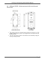
1
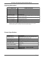
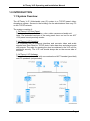
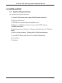
ACTentry V-IP Operating & Installation Instructions 18-00082 Rev 2.0 Issue 2 This manual refers to ACTentry V-IP, a TCP/IP based door videophone system. Access Control Technology Ltd. reserve the right to change the contents of this manual and the system it applies to without prior notice. While every effort has been taken by ACT to ensure the accuracy of the information contained within this document, ACT assumes no responsibility for any errors or omissions. No liability is assumed for damages resulting from the use of information contained within this document. Access Control Technology Unit C1, South City Business Centre, Tallaght, Dublin 24, Ireland. Tel: 353-1-4662570 UK LoCall: 0845 300 5204 Fax: 353-1-4520427 Web: www.accesscontrol.ie E-mail: [email protected] Copyright 2012 Access Control Technology Ltd. Rev 2.0 Issue 2 ACTentry V-IP Operating and Installation Manual Table of Contents Ordering Information ............................................................................................. 3 Product Specification ............................................................................................ 3 1.0 INTRODUCTION ........................................................................................ 4 1.1 System Overview ..................................................................................... 4 2.0 INSTALLATION .......................................................................................... 5 2.1 System Requirements .......................................................................... 5 2.2 Installing ACTentry V-IP door panel ..................................................... 6 2.3 Installing the ACTentry V-IP Unit ........................................................ 10 2.4 ACTentry V-IP connection to the network ........................................... 10 2.5 ACT handset and PC speaker connection .......................................... 11 2.6 ACT handset mounting ....................................................................... 12 2.7 ACTpro-X 1030 Panel-Mount reader installation ................................ 13 2.8 ACTentry V-IP software installation .................................................... 14 2.9 ACTentry V-IP software configuration ................................................ 14 2.10 Configure Settings ........................................................................... 16 3.0 OPERATION ............................................................................................ 19 4.0 TROUBLESHOOTING ............................................................................. 20 5.0 SETTING A FIXED IP ADDRESS ............................................................ 24 6.0 ACTentry V-IP panel Mount Installation Diagram ..................................... 26 7.0 Installation Notice for Flush mount units................................................... 27 8.0 Mounting instructions for Extended Version of ACTentry V-IP. ................ 28 Page 2 ACTentry V-IP Operating and Installation Manual Ordering Information ACT Product Code ACTentry V-IP SK ACTentry V-IP FK ACTentry V-IP SP ACTentry V-IP FP ACTentry V-IP SKX ACTentry V-IP FKX ACTentry V-IP SPX ACTentry V-IP FPX ACTentry V-IP CTR ACTentry V-IP PCH ACTentry V-IP PSU * ** Product description Surface Mount Kit* Flush Mount Kit* VoIP Door Entry Panel (surface ) VoIP Door Entry Panel (flush ) Surface Mount Kit** Flush Mount Kit** VoIP Door Entry Panel (surface) with cut out for panel mount proximity reader VoIP Door Entry Panel (flush) with cut out for panel mount proximity reader V-IP control unit Plug in PC Handset. Internal use only. 1Amp Power Supply Unit. Vandal resistant VoIP Door Entry Panel, PC handset, Control Unit & Power Supply Extended Version: Vandal resistant VoIP Door Entry Panel with cut-out for panelmount proximity reader, PC handset, Control Unit & Power Supply. Product Specification Number of PC’s Number of Doors Supply Voltage Current Consumption Operating Temperature Door Open Time Relay Contact Rating Entrance Panel Size Water Resistance 25 maximum 8 maximum (each door with individual Door Panel and V-IP controller unit) 10-15Volts DC 600mA -10 to +50 degrees C 1 – 255 seconds (4 minutes and 15 seconds maximum) Door Relay 5A / 50Vac, Alarm Relay 1A / 50Vac Flush Mount: 243.5 X 125 mm Surface Mount: 266.5 X 124 mm Medium IP54 Page 3 ACTentry V-IP Operating and Installation Manual 1.0 INTRODUCTION 1.1 System Overview The ACTentry V-IP (Video/audio over IP) system is a TCP/IP based videodoorphone system. Access to the building can be administered from any PC on the TCP/IP network. The system consists of: 1. ACTentry V-IP Door Panel: The door panel has a Call button, colour video camera and audio unit. Note: The extended versions of the entry panel has a cut out for an ACT 1030 panel mount proximity reader. 2. ACTentry V-IP Controller: The controller has an Ethernet interface and converts video and audio signals from Door Panel to TCP/IP data. It also has door and alarm inputs and outputs. The relay for opening the door is contained in the V-IP unit for additional security. The V-IP unit should always be on the secure side of the door. 3. ACTentry V-IP Software: The software requires a PC with a soundcard and ACT handset (provided) and PC speakers (not provided). Page 4 ACTentry V-IP Operating and Installation Manual 2.0 INSTALLATION 2.1 System Requirements The minimum PC requirements are: 1. Colour SVGA monitor with at least 800x600 screen resolution 2. Mouse and keyboard 3. CDROM drive (required during installation only) 4. Ethernet or FastEthernet LAN connection with TCP/IP protocol (100MBps preferable) 5. Operating systems: Windows 7, Windows Vista, Windows XP (32bit and 64bit), 6. 32-bit or 64bit processor, 1GBytes RAM, 16GB hard disk space. 7. Local DHCP Server (see section 5 for fixed IP addressing) 8. Sound Card 9. Speakers Page 5 ACTentry V-IP Operating and Installation Manual 2.2 Installing ACTentry V-IP door panel Page 6 ACTentry V-IP Operating and Installation Manual The ACTentry V-IP door panel is available in Flush-mount or Surface-Mount versions. 1. Flush-mount Flush mount Back Box Page 7 ACTentry V-IP Operating and Installation Manual The flush-mount version comprises of two parts: 1. Flush mount back box 2. Flush mount plate The flush mount back box (previous page) should be sunk into the mounting surface. Ensure to mount it at a height where the camera lens will match eye level. The flush-mount back box can be fixed to the wall via the screw holes provided by the side flaps or the back surface. Attach the flush mount plate (below) to the back box using the security screws provided. Flush Plate Front Panel Fix the door front panel to the flush mount assembly using 6 security screws provided. Page 8 ACTentry V-IP Operating and Installation Manual 2. Surface mount Surface Mount Box Front Panel The surface mount box (shown above) should be mounted on a flat surface, taking care to mount it at a height where the camera lens will match eye level. The door front panel is fixed to the surface mount assembly using the security screws provided. Page 9 ACTentry V-IP Operating and Installation Manual 2.3 Installing the ACTentry V-IP Unit Please follow the guidelines below when installing the ACTentry V-IP unit: 1. The ACTentry V-IP controller unit should be mounted in a secure area close to a TCP/IP network connection point. 2. The recommended maximum distance between the ACTentry panel and the V-IP controller unit is 100m using Cat5 cable (or equivalent) 3. A 12Volt DC, 1 Amp power supply is provided to power the ACTentry V-IP Unit and the ACTentry V-IP door panel audio and video modules. 4. The ACTentry V-IP door panel and ACTentry V-IP controller unit are to be wired according to the wiring diagram at the back of this manual. Door Inputs There are two inputs on the ACTentry V-IP unit: Request to exit (RTE) button will release the door. Door Contact (DC) input monitors the door state (open or closed). Alarm Relay The ACTentry V-IP unit also comes with a built in alarm relay. The alarm relay switches while either the following conditions are in place: 1. Tamper open i.e. lid of ACTentry V-IP box open. 2. Door Contact input open i.e. door forced open. The alarm relay can only be reset when both the Door Contact input and tamper are closed. 2.4 ACTentry V-IP connection to the network Connect the ACTentry V-IP to the Ethernet network with CAT 5 cable. The ACTentry V-IP unit supports DHCP. It will automatically be assigned an IP address from the DHCP server when connected to the network. (A fixed IP address may also be assigned, see section 5.0). The LED’s on the PCB indicate the status of the connection to the network. 1. When both LEDs flash slowly no more than once per second, the ACTentry V-IP controller unit is powered but not connected to the network. 2. When the green LINK LED is on, the ACTentry V-IP is successfully connected to the network. 3. The red TX/RX LED indicates data transmission between the network and the device. Page 10 ACTentry V-IP Operating and Installation Manual 2.5 ACT handset and PC speaker connection 1. The ACT Handset and PC speakers should be connected according to the diagram above. 2. The PC speakers should be powered and switched on. 3. The PC speakers jack plug (green) should be plugged into the ACT handset jack socket (green). 4. The ACT handset microphone jack plug (pink/purple) should be plugged into the PC soundcard Microphone socket, usually symbolised by the following… Microphone 5. The ACT handset speaker jack plug (green) should be plugged into the PC soundcard Lineout or headset jack socket (green). These are usually symbolised by the following: Line Out Headset Page 11 ACTentry V-IP Operating and Installation Manual 2.6 ACT handset mounting A handset holder is provided with the ACT handset. This should be mounted in a location that is easily accessible for the user but not obstructive for the user (as shown below). Before attaching the holder, clean the mounting area with soap and water, (do NOT use solvents) let the area dry. Remove the foil from the adhesive tape and press the holder firmly against the mounting surface. Wait a few hours before hanging up the handset for maximum adhesion. A cable clamp is also provided for cable management. It is also possible to simply place the handset on the desk, without using the mounting holder. If the phone and cord are not impeded, the handset and its switch will function properly. Page 12 ACTentry V-IP Operating and Installation Manual 2.7 ACTpro-X 1030 Panel-Mount reader installation ACTentry V-IP may be used in conjunction with an ACTpro access control system. Cardholders present their proximity cards to the panel mount reader to gain access. Visitors use the call button on the door panel. Please see the ACTpro-X 1030 panel mount installation diagram at end of this manual. The ACTSmart1070 Panel Mount Reader may also be used with the ACTentry V-IP. This is suitable for smaller systems with fewer cardholders and doors (less than 16). Page 13 ACTentry V-IP Operating and Installation Manual 2.8 ACTentry V-IP software installation The V-IP unit needs to be powered up and connected to the network before proceeding with the installation. ACTentry V-IP software is designed to operate on a PC connected to a TCP/IP network. The ACTentry V-IP software should be installed on any PC where the user is expected to answer calls from the door and allow access to the building. To install ACTentry V-IP, insert the CD into your computers CD drive. If Autoplay is enabled, the setup application will load automatically. To load setup manually, select the CD drive from Windows Explorer and double click the SETUP.EXE file. 2.9 ACTentry V-IP software configuration On using the ACTentry V-IP software for the first time, add the ACTentry V-IP units to the software. a. Click on the ACTentry icon in the system tray or on the desktop. b. Select “Setting” on the top right of the screen Network Tab i. Check the correct Ethernet adapter is selected ii. Check the bandwidth is set appropriately set for the network and computer. For very busy networks, the bandwidth may need to be reduced. Language Tab i. Select the language from the dropdown list of languages. c. Click “Find V-IPs” button. Page 14 ACTentry V-IP Operating and Installation Manual A list of available ACTentry V-IP units on the network (LAN) will be displayed. d. “Tick” the units to be monitored by the ACTentry V-IP software. e. Click the “Apply” button to save changes. An icon representing the V-IP unit will appear on the left column. f. Click the icon for each ACTentry V-IP unit and press the “Connect” button to get live audio and video from the unit. g. Click the “Allow” button to open the door and disconnect or Click the “Deny” button to disconnect. Page 15 ACTentry V-IP Operating and Installation Manual 2.10 Configure Settings a. Click Setup button to configure the settings for the selected V-IP unit. Page 16 ACTentry V-IP Operating and Installation Manual Door Name: This is the name that will appear on the application and in reports. By default it is the IP address of the V-IP. A more user friendly name (e.g. Front Door) may be entered here. Door Open Time: This option specifies the length of time the Door Lock remains open before it closes and locks the door again. This should be set to a value that allows for all expected scenarios. By default it is set to 5 seconds. Call Duration: This timer specifies the length of time a PC user who has answered a call can view the live video and may grant or deny access. Pop-Up Delay: This timer specifies the time between the visitor pressing the call button and the notification appearing on the PC screen. Normally this is set to 0, so that the PC user is notified immediately. Another PC user could have this set to, say, 20 seconds. If the main PC user has not answered the call within 20 seconds, it will pop-up on the other PC. IP Address: This is the IP address of the V-IP unit and is read-only. Version: This is the firmware version of the V-IP unit and is read-only. Page 17 ACTentry V-IP Operating and Installation Manual b. Click on Audio Tab to configure sound card settings in the PC. To help configure the audio properties, a second person is required at the door V-IP panel. Check that the person at the door can be heard from the PC speakers or the PC handset. PC Speaker: When the call button is pressed, the call sound should be heard over the PC speakers. Set the volume level with the slider. Handset: Adjust the volume settings of the handset to hear the person at the door . Further adjustments can be made to volume of the handset or the PC speakers by their own volume controls. Microphone: If the person at the door panel cannot hear the PC user, adjust the Microphone sensitivity. c. Click Apply to save changes. The V-IP is now ready for use. Page 18 ACTentry V-IP Operating and Installation Manual 3.0 OPERATION When the call button at the ACTentry V-IP entry panel is pressed, the ACTentry software will immediately pop-up a notification at the bottom right of the monitor. When the “Pop-Up Delay” is longer than 0 seconds the ACTentry V-IP software will wait for the delay time before popping up the notification unless the call is answered by another operator. Click Answer button and the video from the door will pop up on-screen. The ACT handset should be lifted and used to converse with the person at the door and access may or may not be granted accordingly with the Allow or Deny buttons. If the Pop-Up is not answered, it will time-out after 60 seconds. Alternatively, clicking Ignore will remove the pop-up from the screen. Page 19 ACTentry V-IP Operating and Installation Manual 4.0 TROUBLESHOOTING 4.1 No V-IPs found on the network Check that all V-IP units are powered up and connected to the Local Area Network. On the V-IP unit, check the green LINK LED is on. Check the network settings under Settings on the top right. Choose the correct Network Adapter on the machine. Page 20 ACTentry V-IP Operating and Installation Manual 4.2 Audio Feedback is heard by PC user when connected to live video Lift the ACT Handset and listen. Go to the Audio Settings and decrease the microphone sensitivity and speaker volumes. The feedback should now be gone. Increase the volume settings for the speaker and microphone in small adjustments until satisfactory volume levels are received in both, making sure no feedback occurs. If feedback persists, check the wiring between the ACTentry V-IP controller and the audio unit. Audio Out and MIC In from the controller should be wired to T and R respectively of the audio unit panel on a twisted pair. 4.3 Difficult to hear the person at the door Turn up the volume on the handset. Increase the Handset volume setting from the application. Page 21 ACTentry V-IP Operating and Installation Manual 4.4 The person at the door cannot hear PC User Increase the Microphone sensitivity in Audio Settings. From the PC, click Start, Control Panel, Sound, Recording and check the Microphone properties. Raise the microphone levels and increase the boost. Also check the following: 1. Ensure that the Speaker Grill is fitted securely against the Door Entry Panel Grill. 2. Check the Door Entry Panel Grill for any blockages. 3. Check that the supply voltage is not at an inadequate level. For best operation it should be between 10V and 15V between terminals marked C and H on the speech unit. 4. Check the handset connections to the PC are correct. Page 22 ACTentry V-IP Operating and Installation Manual 4.5 Video picture is poor quality or grainy The bandwidth can be increased. Go to Settings in the ACTentry V-IP application and select bandwidth of 1024Kb/s. Also check the video signal and 0V are on the same twisted pair. 4.6 Call Button not making call when pressed Check the V-IP plays a sound when call button pressed. If not check the call button wiring. One call wire should connect to the Call input on the ACTentry V-IP unit. The other connection on the call button is connected to 0V The “Grant Access” option does not open the door 4.7 Check the wiring between the Lock Relay terminals on the ACTentry VIP unit and the lock Use a multi-meter to check that the Lock Relay on the ACTentry V-IP is switching over. 4.8 Alarm is constantly on Check the Tamper spring on the ACTentry V-IP unit is fitted and not impeded by wiring. Ensure the Door Contact (DC) input on the ACTentry V-IP unit is linked to 0V. Power down and power up the ACTentry V-IP unit again. Page 23 ACTentry V-IP Operating and Installation Manual 5.0 SETTING A FIXED IP ADDRESS By default the V-IP unit is supplied with support for DHCP server only. The IP address is assigned by the server when the device powers up. In some circumstances it might be necessary to fix the IP address of the V-IP unit. To configure a fixed IP address, you need to use telnet, (which is not available on Vista machines). If the V-IP unit already has a known IP address, then to change it to a fixed address, do the following: 1. Type cmd 2. telnet <IP ADDRESS of V-IP Unit> e.g. telnet 172.27.72.85 3. When prompted for the password, enter ACT 4. Type ? to get a list of commands 5. To set the ip address enter: setip <ip address> <gateway> <subnetmask> Eg. setip 172.27.72.63 172.27.72.254 255.255.255.0 6. IP address is now set to 172.27.72.63 7. Type quit to exit. Page 24 ACTentry V-IP Operating and Installation Manual If the V-IP unit does not have a known IP address, then it can be set to a default value by doing the following: 1. Power up the unit 2. Remove Link J307 on the top right hand side of board. 3. LED DS1 (first LED on daughter card) flashes 4. Hold down the tamper switch for 3 seconds 5. LED DS1 stays on 6. Replace Link J307 7. LED DS3 (third LED) flashes 8. Power down the unit. 9. Power up the unit. 10. IP address now set to 192.168.1.66 11. To change the IP address follow the procedure above. If you want to set the V-IP unit back to DHCP mode, then: 1. Type cmd 2. telnet <IP ADDRESS> 3. Password: ACT 4. Enter setip 0 5. V-IP is now set for DHCP mode 6. Type quit Alternatively: 1. Power up the unit 2. Remove Link J307 on the top right hand side of V-IP board. 3. Power down the unit 4. Replace Link J307 5. Power up the unit Page 25 ACTentry V-IP Operating and Installation Manual 6.0 ACTentry V-IP panel Mount Installation Diagram Page 26 ACTentry V-IP Operating and Installation Manual 7.0 Installation Notice for Flush mount units. Page 27 ACTentry V-IP Operating and Installation Manual 8.0 Mounting instructions for Extended Version of ACTentry V-IP. The ACTentry V-IP door panel is available in Flush-mount or Surface-Mount versions with a cut out for panel mount readers. 8.1 ACTentry V-IP FPX - Flush-mount panel with cut out for panel mount reader Back Box Page 28 ACTentry V-IP Operating and Installation Manual The flush-mount version comprises of two parts: 1. Flush mount back box 2. Flush mount plate The flush mount back box (shown above) should be sunk into the mounting surface. Ensure to mount it at a height where the camera lens will match eye level. The flush-mount back box can be fixed to the wall via the screw holes provided by the side flaps or the back surface. Attach the flush mount plate (below) to the back box using the security screws provided. Flush Plate Front Panel Finally, fix the door front panel to the flush mount assembly using 6 security screws provided. Page 29 ACTentry V-IP Operating and Installation Manual 8.2 ACTentry V-IP SPX – Surface mount panel with cut out for panel mount reader Surface Mount Box Front Panel The surface mount box (shown above) should be mounted on a flat surface, taking care to mount it at a height where the camera lens will match eye level. The door front panel is fixed to the surface mount assembly using the security screws provided. Page 30 ACTentry V-IP Operating and Installation Manual Ordering Information: ACT Product Code ACTentry V-IP SK ACTentry V-IP FK ACTentry V-IP SP ACTentry V-IP FP ACTentry V-IP SKX ACTentry V-IP FKX ACTentry V-IP SPX ACTentry V-IP FPX ACTentry V-IP CTR ACTentry V-IP PCH ACTentry V-IP PSU Product description Surface Mount Kit* Flush Mount Kit* VoIP Door Entry Panel (surface ) VoIP Door Entry Panel (flush ) Surface Mount Kit** Flush Mount Kit** VoIP Door Entry Panel (surface) with cut out for panel mount proximity reader VoIP Door Entry Panel (flush) with cut out for panel mount proximity reader V-IP control unit Plug in PC Handset. Internal use only. 1Amp Power Supply Unit. *Vandal resistant VoIP Door Entry Panel, PC handset, Control Unit & Power Supply **Extended Version: Vandal resistant VoIP Door Entry Panel with cut-out for panelmount proximity reader, PC handset, Control Unit & Power Supply. ACT Contact Details: Tel: +353-1-4662570 UK LoCall: 0845 300 5204 Fax: +353-1-4662570 Web: www.accesscontrol.ie E-mail: [email protected] E-mail: [email protected] Page 31