1
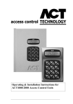
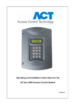
ACT entry A10
Operating & Installation
Instructions
18-00044
ACTentry A10 Operating and Installation Instructions
Installation Notes
• Remember to Factory Default the ACTentry A10 before programming
• Remember to place the supplied varistor across the terminals of the door strike coil to protect the relay
contacts
• Never use the on-board relay to switch AC mains voltage. An external relay, electrically isolated from
the ACTentry A10 should be used for this purpose.
• Remember to change the programming code.
Important
As with any Access Control system, always ensure there is an alternate means of escape in the event of
the unit failing to operate due to power loss or in the event offi re.
Product Specification
Number of Users
Supply Voltage
Current Consumption
Operating Temperature
Door Open Time
Relay Contact Rating
Controller Size
Water Resistance
10 PIN codes
12 V AC or DC
30mA (nominal), 100mA (maximum)
-10 to +50 degrees C
0 - 4 minutes
5A / 50Vac
Flush Mount 378 x 144 x 11mm
Surface Mount: 358 x 125 x 38mm
Medium IP54
Ordering Information
ACTentryA10VR-SK
Vandal Resistant Door Entry Panel with integrated ACT 10 Digital Keypad, Call Button
and Speech Unit in a Surface Mount Kit, Door Intercom Handset & Power Supply
ACTentryA10VR-FK
Vandal Resistant Door Entry Panel with integrated ACT 10 Digital Keypad, Call Button
and Speech Unit in a Flush Mount Kit, Door Intercom Handset and Power Supply
ACTentryA10VR-S
Vandal Resistant Door Entry Panel with integrated ACT 10 Digital Keypad, Call Button
and Speech Unit for Surface Mounting
ACTentryA10VR-F
Vandal Resistant Door Entry Panel with integrated ACT 10 Digital Keypad, Call Button
and Speech Unit for Flush Mounting
ACTentry A10
Intercom Handset
ACTentry Door Intercom Handset for use with the ACTentry A10. Internal use only.
ACTentry 1A PSU
This is a 1 Amp Power Supply Unit
2
ACTentry A10 Operating and Installation Instructions
ACTentry A10 Schematic
3
ACTentry A10 Operating and Installation Instructions
Quick Programming Guide
(For typical System)
1. Enter Programming Mode.
On the digital keypad press button . Input the programming code (default is 9999).
(e.g Enter Programming Mode: -9999)
2. Change User 1 Code
On the digital keypad: Press Button 0, then Press Button 1 (for User 1). Input the new User 1
code (4 digits). (e.g. Change User 1 Code to 4321: -9999-0-1-4321- )
3. Change Programming code
On the digital keypad: Press Button 0, then Press Button . Input the new programming code
(4 digits). (e.g. Change a Programming Code to 9876: -9999-0-tick-9876- )
4. Exit Programming Mode
On the digital keypad press button . The yellow LED indicator stops flashing. Programming
code has been exited.
The ACTentry A10 is now ready for normal use. Test the operation of the code.
Note: The ACTentry A10 may be returned to its factory default condition at any time by entering the
programming mode and pressing button three times.
For Door 2 Operation
1. Enter Programming Mode. (e.g Enter Programming Mode: -9999)
2. Change User 2 Code
On the digital keypad: Press Button 0, then Press Button 2 (for User 2). Input the new User 2
code (4 digits) (e.g. Change User 2 Code to 4441: -9999-0-2-4441- )
3. Assign User 2 to Door 2
On the digital keypad: Press Button 1, then Press Button 2 (for User 2), then Press Button 2 (for
Door 2). (e.g. Assign User 2 to Door 2: - 9999-1-2-2- )
4. Exit Programming Mode
User 2 code will now activate Door 2 Relay.
Unit C1, South City Business Centre, Tallaght, Dublin 24, Ireland
Tel: 353-1-4662570 Fax: 353-1-4520427 UK Locall: 0845 300 5204
Web: http://www.accesscontrol.ie E-mail: [email protected]
Copyright© 2008 Access Control Technology Ltd.
4
ACTentry A10 Operating and Installation Instructions
ACTentry A10 Operation
The ACTentry A10 is a simple, easy-to-use access control unit combining digital keypad and door-entry
telephone technologies. The ACTentry A10 Door Entry Panel incorporates a call button for the Door
Intercom Handset, Speech Unit (grill, microphone and speaker) and ACT 10 Digital Keypad.
For residents or legitimate personnel, their PIN code, entered on the digital keypad, will unlock the door
for a preset time. The unit supports a maximum of 10 PIN codes. Visitors can press the call button to
request entry, which creates a call to a Door Intercom Handset located within the building. The operator
can speak to the visitor before granting or denying access
ACTentry A10 Installation
Read carefully all the information presented in this section and then install the ACTentryA10 in
accordance with the wiring diagram below. The door entry panel is supplied with either a surface or
shelteredlocation.
Cable Requirements:
For optimum speech clarity, it is strongly recommended that the ACTentry A10 system is installed using
twisted-pair telephone cable (eg type CW1308). Use one of the pairs for the R&O connection between
the speech unit and the telephone/intercom handset.
Using CW1308 Cabling:
Connections
Phone
Exit
PSU
Number of Cores
5
2
2
Core diameter
0.5mm
0.5mm
0.5mm
Max. Cable Length
100 metres
100 metres
15metres
The ACTentry A10 may be installed also with 2 CAT5 cables. Use one cable for the PSU. Combine 4
cores for positive and 4 cores for negative. Use the other cable for the phone and the exit button.
Using CAT 5 Cabling:
Connections
Phone
Exit
PSU
Number of Cores
5
2
4 for positive, 4 for negative
Max. Cable Length
100 metres
100 metres
100 metres
Speech Adjustment
The speech unit has two adjustable potentiometers for changing the speech levels:
Volume A: Speech level at the entrance panel
Volume B: Speech level at the telephone
5
ACTentry A10 Operating and Installation Instructions
ACTentry A10 Programming
Press the button followed by the programming code (initially 9999). The yellow LED will flash while
in programming mode. To exit the programming mode press button . Exit from programming mode
occurs automatically if no key is activated for 30 seconds.
Changing Codes:
(From programming mode)
Enter
0
(Change codes)
0-9,
(user number 0-9, = programming code)
000000-999999
(4 or 6 digit code – 000000 deletes user)
Default user codes: Programming = 9999(99), User 1 =1234(56), All others inactive.
Setting switched output combinations:
(From programming mode)
Enter
1
(Set Outputs)
0-9
(User number 0-9)
0-7
(Output function code)
Output Function Code
0
1
2
3
4
5
6
7
Door Output
Door 2/Output 2
Timed
Timed
Timed
Toggled
Timed
Timed
Timed
Timed
Timed
Output 3
Timed
Timed
Timed
Timed
Default function code is 1 (Relay Timed) for all users. When the door is toggled open, this will be
For example, to set user 1 to toggle the door open/locked:
Enter 1(set outputs), followed by 1(user1), followed by 0(Toggled). (e.g -9999-1-1-0- )
To set user 2 to open Door 2:
Enter 1(set outputs), followed by 2(user2), followed by 2 (Door 2 timed) (e.g. -9999-1-2-2- )
Setting timers:
(From programming mode)
Enter
2
(Set Timers
0-4
(Timer number) {Buzzer sounds indicating timing… wait required period}
(Stop timing) {Buzzer stops – timer set}
6
ACTentry A10 Operating and Installation Instructions
Timer No.
Function
Default
0
Relay time
5s
1
Door 2 / Output 2 time
5s
2
Output 3 time
5s
3
Door Ajar time
30s
4
Guest Buzzer time
2s
Timers may be set to any duration between 2 seconds and 4 minutes.
Setting Configuration:
(From programming mode)
Enter
30-37 or 40-47
0-1
(Option number)
(1= Set, 0 = Unset)
Option
Function
Default
Operation
30
Door Chime
Off
When set, whenever the door contact is opened, the built-in buzzer makes a
chime sound and the buzzer output activates for 2 seconds.
31
Silent Operation
Off
When set, the keypad operates silently, that is no audible tones (key-presses
or confirm tones) are produced from the built-in buzzer function (function 0).
32
Permanent
Backlighting
On
When set (default), the keypad illumination is always on. This option will
override option 42 (Auto backlighting)
33
Locksaver
(Anti Tailgating)
Off
When set, and when the relay is active (following a valid code or buttonr elease),
the relay timer is truncated to 2 seconds when the door contact opens. This
ensures that irrespective of programmed relay time, the door will be locked
as soon as it closes, and any person following will have to enter a code.
34
Alarm
Keypad
Operation
Off
When set, the keypad may be used as a remote keypad for an alarm system. The red
and green indicators are controlled by the door contact and the release button inputs
inputs respectively, and the built in buzzer is controlled by the interlock input.
35
Interlock
Off
When set, two or more keypads may be interlocked so that only one controlled
door may be open at any one time. The interlock output is active whenever the
relay is active or when the door contact is open. When the interlock input is
active the release button and all codes are inactive, and the red indicator flashes.
The interlock outputs and inputs of any number of keypads may be combined
on a single wire.
36
Six Digit Codes
Codes
Off
When set, all user codes, and the programming code, are six digits long. The
default user one code becomes 123456 and the default programmer code
becomes 999999.
37
Twin Codes
Off
When set, two different codes must be entered within 15 seconds in order to
open the door. The outputs activated are those which have been programmed
for the first code to be entered.
7
ACTentry A10 Operating and Installation Instructions
Option
Function
Default
Operation
40
Door Forced
Alarm
Off
When set, the buzzer output is activated, if the door contact opens when a valid
code has not been entered. The output is deactivated when a valid code is next
entered. This is useful for monitoring fire doors etc.
41
Group Disable
Off
When set, the top five user codes (5-9) are inactive any time the interlock input
is activated. This restricts access to certain codes under external control (i.e. an
alarm system output or a time clock).
42
Auto
backlighting
Off
When set, the keypad illumination is normally off, but will switch on in
response to any key being pressed or while in programming mode. This option
is overridden by option 32 (permanent backlighting). To prevent any
illumination, unset options 32 and 42.
43
Door Ajar
Alarm
Off
When set, and the door contact has been open for longer than the time programmed
into the door ajar timer, the built–in and external buzzers sound intermittently. The
buzzers may be silenced by closing the door and entering a valid code.
44
Guest Button
On
When set (default) and when the ✔ button on the keypad is pressed, the buzzer
output is activated for the duration programmed into the guest buzzer timer.
45
Fire Alarm
Override
Off
When set, the relay is held active whenever the interlock input is active, and
the green indicator will flash. This is useful for allowing a fire alarm system
to override controlled doors.
46
Release Button
for Second door
Off
When set, the keypad activates the door 2 relay which follows output 2’s timer.
This allows two doors to be controlled using one keypad.
47
Duress
Off
When set, and when a duress code is entered, the door is opened normally and
output 2 is activated. A duress code is any valid user code with one added to
the last digit. The output will be reset when a valid user code is entered. When
the duress option is set, user codes which have 9 as the last digit should be
avoided as there is no corresponding duress code.
Incorrect Code Lockout
When three invalid codes have been entered in a row, the keypad will enter lockout mode for 20 seconds.
During this time, the red LED indicator will flash and all PIN codes will be inactive.
Restoring Factory Defaults
Enter Programming Code followed by ✔✔✔. This restores the ACTentryA10 to its default settings.
If the Programming Code has been forgotten, it may be set to 9999 by:
1.
2.
3.
4.
5.
6.
Remove the power from the unit.
Remove link LK1 at the back of the unit.
Apply power to unit.
Replace link LK1.
Remove power again
Restore power and proceed with programming.
Note: The keypad will not operate correctly without LK1 in place.
8
ACTentry A10 Operating and Installation Instructions
Troubleshooting
We have identified a number of issues that may occur during or after installation that may reduce the
quality of the ACTentry A10 operation. If you do not feel your system is working at an optimum level
please review the following prior to contacting our Technical Support Helpdesk.
Low Volume through the Speaker Grill on the Door Entry Panel
Please check the following:
1. Adjust the Volume from the Speech Unit by adjusting control A.
2. Ensure that the Speaker Grill is fitted securely against the Door Entry Panel Grill.
3. Check the Door Entry Panel Grill for any blockages
4. Check that the supply voltage is at an adequate level. For best operation it should be
between 10V and 15V between terminals marked C and H on the speech unit.
When in use a constant tone/feedback (howl or whistle) is experienced from the Speech Unit
1. Volume adjustment may be required on the Speech Unit contained in the Door Entry Panel.
Turn both A and B controls “off”. Turn back on and slowly adjust each control in turn until
the optimum volume has been achieved.
2. Ensure that the Speaker Grill unit is fitted securely against the Door Entry Panel Grill.
3. The “O” connection from Speech Unit and the Door Intercom Handset is disconnected.
This will dramatically reduce the feedback threshold. Check your wiring for this fault.
4. The Door Entry Panel and the Door Intercom Handset are too close together. You
should not be able to hear the caller without the use of the Door Intercom Handset.
5. The Door Entry Panel is surrounded by reflecting walls e.g. a basement flat. In this situation
acoustic feedback may occur at lower volume levels. It may be necessary to change the
position or orientation of the panel.
6. Check the Door Entry Panel Grill for any blockages
The Caller cannot be heard through the Door Intercom Handset
1. This could indicate a wiring fault on the speech signal connections R or T.
• R carries the audio from the Door Intercom Handset to the Door Entry Panel.
• T carries audio from the Door Entry Panel to the Door Intercom Handset.
The Door Intercom Handset will not buzz
1. This could indicate a faulty “O” or “I” line between the power supply and the Door
Intercom Handset.
• To test this check for a reading of between 10.5V – 15V between I and O when called.
The Door Intercom Handset ‘DOOR’ button does not operate release
1. Check for a fault on the Z or O line
2. Check that there is not a missing connection to the ACTentry A10 PUSH BUTTON terminal.
Unit C1, South City Business Centre, Tallaght, Dublin 24, Ireland
Tel: 353-1-4662570 Fax: 353-1-4520427 UK Locall: 0845 300 5204
Web: http://www.accesscontrol.ie E-mail: [email protected]
Copyright © 2007 Access Control Technology Ltd.
9
ACTentryA10 Operating and Installation Instructions
T y p i c a l A C Te n t r
guration
(Energised Lock)
Door Intercom
Handset
(base of)
Run O and R as twisted-pair
0V
+V
I RO T Z
CHROT
Volume A Adjust
Volume B Adjust
Speech Unit
I RO T Z
Call Button
A maximum of 4
Door Intercom
Handsets per
Door Entry Panel
+V
ACT 10 Keypad
12
AC/DC
+V
+
N/C
LK1
Power Supply
12 V AC / DC
0V
C
5A
250V
AC
5A 30VDC
INPUTS
0V
Buzzer
OP3
Duress
OP2
Interlock
RELAY
DOOR 2
TAMPER
5A
25 0 V A C
5A
30VDC
OUTPUTS
0V
Interlock
(PB2)
Push
Button
Door
Contact
Volt-Free
Tamper Contacts
N/O
OMRON
OMRON
Door Release
Button
Important!
Always Place Varistor
Across All Lock Terminals
Normally Energised lock shown.
N/O
C
N/C
(Rear View)
10
ACTentry A10 Operating and Installation Instructions
T y p i c a l A C Te n t r
guration
(De-energised Lock)
Door Intercom
Handset
(base of)
Run O and R as twisted-pair
0V
+V
CHROT
Volume A Adjust
Volume B Adjust
I RO T Z
Speech Unit
Call Button
+V
ACT 10 Keypad
12
AC/DC
+V
+
N/C
LK1
0V
Power Supply
12 V AC / DC
C
5A
250V
AC
5A 30VDC
INPUTS
0V
Buzzer
OP3
Duress
OP2
Interlock
RELAY
DOOR 2
TAMPER
52A5 0VAC
53A0 V D C
OUTPUTS
0V
Interlock
(PB2)
Push
Button
Door
Contact
Volt-Free
Tamper Contacts
N/O
OMRON
OMRON
Door Release
Button
Important!
Always Place Varistor
Across All Lock Terminals
Normally De-energised lock shown.
N/O
C
N/C
(Rear View)
11
User List
Unit C1, South City Business Centre,
Tallaght, Dublin 24, Ireland
Tel: 353-1-4662570 Fax: 353-1-4520427 UK Locall: 0845 300 5204
Web: http://www.accesscontrol.ie E-mail: [email protected]
Copyright© 2008 Access Control Technology Ltd.