1
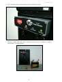
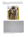
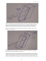
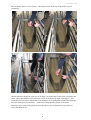
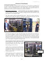
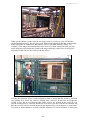
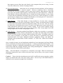
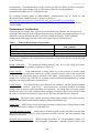
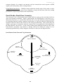
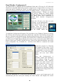
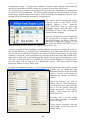
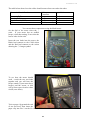
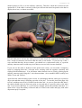
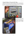
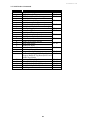
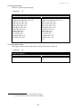
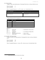
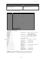
Rev Australasia V2.3 12/04 Allflex RFID Panel and Portal Readers User Manual (Version 2.4 April 2006) 1 Rev Australasia V2.3 12/04 Panel Reader User Manual Document Control Form Allflex Australia Pty Ltd Document Information Document Name : Panel Antenna User Manual Current Version Number : V 2.4 Description : User instruction manual. Distributed with Allflex Panel Antenna package Document Changes Made By : Pat Gunston Version History Version Number V 2.0 V 2.1 V 2.2 V 2.3 V 2.4 Date Details 2/8/04 5/8/04 23/9/04 Version history started. Minor changes to layout. Document Control form added. Low voltage indicator description added. 2/12/04 New front cover with Digital Display, Moved Introduction to after Contents page, Fault Finding Flowchart added, Updated installation notes. 01/04/06 Inclusion of section on portal readers 2 Rev Australasia V2.3 12/04 Table of Contents Contents Page Introduction 4 Assembly Instructions 5 Mechanical Installation 7 Electrical Interface Wiring 11 Power Source Requirements 11 Serial Data Communications 12 Performance Verification 13 Panel Read Zone Geometry 14 Interpreting ID Codes 15 Panel Reader Configurator® 16 Configuration Options 18 Panel Reader Tuning 20 Panel Reader Synchronization 20 Technical Specifications 21 Warranty 22 Regulatory Compliance Notices 23 Fault Finding 24 Common Faults 24 Testing Communications 27 Using Hyperterminal© 27 Testing a cable with a Multimeter 33 Appendix 1 – Serial Command Language 35 Caution! Please read the information contained within this Installation Guide prior to attempting installation and operation of the Panel Reader. Failure to install and operate the Panel Reader in accordance with the information contained in this manual may result in unsatisfactory performance. 3 Rev Australasia V2.3 12/04 Introduction The Allflex Panel Reader comprises 2 parts, the antenna and the reader control electronics. The reader section is the electronics that generates the signal used to excite (power up) the RFID device (Radio Frequency ID). The device is also referred to as a transponder, electronic ID (EID), as well as electronic eartag , etc. The reader also decodes the signal returned from the RFID device. The transmission and receipt of signals between the reader and the RFID device is done via the antenna. The antenna is a specifically designed coil of copper wire enclosed within the plastic panel. The Allflex reader is designed to read devices that meet international standards ISO 11784 and 11785. NLIS devices are ISO compliant devices. The reader electronics are housed inside a control box that also includes an ammeter, indicator lamps etc. The control box is usually fastened to the antenna using 2 x 5mm countersunk stainless steel screws. Please see Assembly Section. A cable is supplied to provide 12volts DC to the control box. This cable can be clearly identified because it has alligator clamps on one end. The power source should be a standard automotive, truck or marine battery. A 240 Volt – 12 volt linear power supply is also available as an option. Note : Only the approved linear 240volt supply should be used because most 240 volt supplies will generate electrical interference that may cause the reader to perform poorly. A second cable, the The Allflex Medium Panel Reader (600mm x 400mm) communications cable, is also supplied to join the control box to a computer, scale head etc. Each Panel Reader is factory tuned for optimum performance in an environment free from metal structures. Typically, the system will operate without user adjustment in many installations. Pre-drilled mounting holes in the black panel facilitate user installation, so that total system setup is fast and easy. This instruction guide provides the user / installer with information about mechanical installation, electrical wiring, configuration, operation, and performance characteristics of the Panel Readers. 4 Rev Austalasia V2.3 12/04 Assembly Instruction 1. The Control Box mounts onto the panel as shown below. Note: the control box mounts in different locations dependant upon the size of the antenna (as shown below). Control Box Antenna The Allflex medium size panel antenna 2. The system can be supplied with either a standard 500 mm cable, or an optional 5 metre cable to join the control box to the antenna. Usually, when using the standard cable, the control box can be fastened to the antenna using the two 5mm countersunk Stainless Steel screws provided with the antenna. 3. Screw the Control Box onto the panel using the pre-drilled and countersunk holes as shown here. 5 Rev Australasia V2.3 12/04 4. The Control Box joins to the antenna as shown in the picture below. 5. The power supply cable joins to the Control Box and connects to a standard car, truck or tractor battery. (as shown below). 6 Rev Australasia V2.3 12/04 Portal Antenna: The portal antenna is an optional replacement for the flat panel antenna and forms a tunnel that is placed in a stock race. The tunnel can be used bi-directionally. It is a structure formed from plastic that has a vee section base and rises from the ground at an angle of around 60 degrees as shown in the image and sketches below. Note – the portal joins to the control box via the blue cable supplied. Into the structure an antenna is wound an antenna. The antenna involves multiple turns of conductor to form a loop. The loop runs parallel to the edge of the structure so the animal will pass through the loop as it enters the portal / tunnel. 7 Rev Australasia V2.3 12/04 The wire is then laid over to the other edge of the structure, where a second loop is wound. This loop is at the edge where the animal will exit the structure. Therefore the animal will walk through 2 loops formed from one single conductor. The start of the wire and end of the wire terminate at an electrical connector to allow circuit connection to the control electronics. The first coil and second coil are wound in opposite directions (out of phase). This increases immunity to electrical noise. The antenna structure is located between metal pipes section around 1 metre long that run in a horizontal plain. These can simply be sections of metal gates. Ensure they are very firmly fastened so that vibration of the metal is not evident. These pipes act as radiators to expand the antenna read field. The metal bars also allow better coupling with the tag when in a horizontal plain. Many sheep RFID tags sit in a horizontal plain and for a simple panel antenna this is the worst orientation. However, in the portal reader, the effects of tag orientation are essentially removed because of the metal radiators and the fact that 8 Rev Australasia V2.3 12/04 the read field is laid over at 6o degrees. The Images below show tags being read in various orientations. Another benefit of laying the coils over at an angle is to ensure that if a null zone is formed in the centre zone of the antenna, it (the null zone) will be on an opposing angle of 60 degrees. This means that it will be almost impossible for an animal to move through the antenna and follow the null zone (60 degrees to horizontal). Allflex has a Patent Pending for the portal reader. Naturally a key benefit of the portal reader is that there is far less dependency upon what ear carries the RFID device. 9 Rev Australasia V2.3 12/04 The portal can be fastened directly to the metal pipes, or tied firmly in place. 10 Rev Australasia V2.3 12/04 Mechanical Installation Choosing an Installation Site Several factors should be considered when selecting and / or constructing an installation site in order to ensure optimum performance of the Panel Reader. Prior to making structural changes to the target installation site, the user should temporarily install the reader in a manner that as closely as possible simulates the permanent installation. (a) Metal surfaces and structures - The Panel Reader uses radio frequency techniques to communicate with the eartags. Metal material, especially metals that are magnetic can seriously degrade the read range performance through absorption and deflection of the Panel Reader’s electromagnetic fields. The reader cannot usually read through sheet metal. However, in some cases this is possible and the reader can usually be configured to read through metal pipes and still achieve good read distances as demonstrated in the images below. Note that in the images above, the reader has literally been tied directly to the metal bars. In a practical installation, Allflex would recommend that you use a piece of marine plywood (or similar) in between the metal bars and the reader so that the reader is protected from direct impact from horns etc. Also in some cases, when mounting through steel bars, it is necessary to mount the antenna away from the bars. This depends upon the type of crush and the configuration of the pipe work. If you do intend to mount the antenna to read through metal pipes, position the antenna so that the antenna coil, (the raised section) does not sit directly above the pipe work. Try and position the antenna so the coil is offset / spaced between the pipe work as shown. Another issue to consider that will dramatically effect the performance of the reader, is to avoid positioning the antenna so that metal bars run parallel to the antenna coil forming a frame closely around the coil. Hold the antenna in place or temporarily tie it in the desired location. Check the current displayed on the ammeter. Ideally, it should be around 1 amp. You may find that by simply 11 Raised section is the antenna coil Rev Australasia V2.3 12/04 lifting one side away from the steel pipes, the current and read distance will be excellent. Verify that sufficient read range performance is possible. Note the screw driver blade sitting between the panel and the steel. The good read distance shown above has been achieved by lifting one edge off the steel. If you do temporarily position the reader like this, you can then mount the panel reader on ply in the desired position. You can adjust the current up to around one amp, which should give you great reading results, by either packing the antenna off the steel a little (using spacers), lifting one edge away from the steel (as shown above), or by adjusting the tune. Tuning is a process that will adjust the antenna to perform in an area where an amount of conductive metal is in close proximity. This is discussed in detail later, however, if you require assistance, please call Allflex for telephone support. Allflex Australia – 07 3245 9100. Allflex New Zealand - 06 356-7199. In some cases, it is more practical to mount the antenna on a non-metallic material such as timber and simply fit this into the crush (as shown below). This allows easy, installation and removal where the antenna is moved often and also provides excellent read distance. 12 Rev Australasia V2.3 12/04 Antenna mounted on ply When you do mount a reader onto the steel pipe work of a crush etc, you will find the antenna transmits energy into the pipe work. What often happens is that the crush actually starts acting like an extension to the antenna. This is called the Parasitic Effect. For example, if you mount an antenna close to the front of a crush, (head bail end) you may notice that tags read outside the normal read range when they come close to steel pipes positioned at the entry to the crush (as shown below). Usually, this parasitic effect is really helpful because it means that the animal is detected very quickly as it enters the crush or drafting crate, however, it may also mean that the system is very fast to read animals that follow closely the animal in the crush (IE if a second animal places it’s head in beside the first beast, you may read the first animal and then the second, with the second animal being displayed on your computer or scale head). You need to understand how to deal with this situation if it occurs and how it affects the 13 Rev Australasia V2.3 12/04 data capture process either into scale heads, or the computer that you are using. In most cases the software has a means of coping with this. (b) Electrical Machinery - Most 240 volt AC operated electrical machinery will not interfere with the Panel Reader’s electrical signals. However, machinery that is electrically controlled by electronic methods, such as motor speed controls, light dimmers, and solid state relays can produce high frequency emissions that can cause interference. When the Panel Reader is being trial installed, the user should run all the machinery in the vicinity to ensure that all potentially interfering sources do not exist. When wiring an AC mains operated power supply for use with the Panel Reader, avoid wiring the AC connection to the same phase as such electric machinery is wired. (c) Other Eartags - If the Panel Reader is being installed in a location where eartagged animals will exist on all sides of the Reader (such as a feeder), precautions must be taken to ensure that only animals within the designated reading zone are read. This can usually be achieved by positioning sheet metal, or mesh in an appropriate location between the reader and the area where you want to “block” reading. If you do have multiple eartags simultaneously present in the read zone of the antenna, either eartag might read, both eartags might read, or neither eartag might be read. (d) Other Readers - Operating multiple Panel Readers within close proximity, or operating a mobile hand-held reader nearby a Panel Reader, can reduce the read range of all readers present. In some cases this can totally inhibit reading of all readers. If multiple readers are to be used in proximity to each other, it will be necessary to synchronize the readers. Synchronization will require additional hardware equipment. Please call Allflex for assistance with synchronization. Allflex Australia – 07 3245 9100. Allflex New Zealand 06 356-7199. Once a suitable location site and installation method have been determined, the Panel Reader can be permanently mounted in position using the ¼” (6mm) pre-drilled mounting holes. If it is necessary, alternate or additional mounting holes may be drilled by the user, using caution to drill only within the rectangle defined by the existing mounting holes. Standard steel bolts will not compromise Panel Reader performance. Note - The Panel Reader is designed to be completely water-tight. While not intended for installation immersed in water, contact with water spray, such as heavy rain or power washers is acceptable. Caution! - Ensure that the mounting structure itself is sufficiently strong enough to endure impact by animals that will come into contact with it. Do not rely on the Panel Reader to contribute to the structural strength of the installation. 14 Rev Australasia V2.3 12/04 Electrical Installation Electrical installation consists of making the appropriate power and data connections to the user’s equipment. In some installations, where multiple Panel Readers are located and operating at the same time, synchronization wiring will be required. Power Source Requirements The Panel Reader is supplied with a cable that allows direct connection to an automotive, truck or marine battery. A 240 volt powers supply is also available as an option. It is recommended that you use a well charged automotive battery or the recommended 240 supply. This is important because the 240 volt supply is a “linear” regulated type unit rated at 12 VDC output and 3.0 amperes minimum. Some AC power supplies may exhibit excessive noise that can compromise read range of full duplex (FDX-B) (sheep / small stock) type transponders. AC power supplies should be rated at 3 millivolts or less output ripple. Users can purchase the recommended power supply from Allflex. It will be supplied in an appropriate weather-proof enclosure (IP56). Alternatively, users can purchase their own linear power supply and have a suitably qualified electrician mount the device into an appropriate enclosure. The linear supply required is a Condor brand, part number HC12-3.4+. The part can be purchased directly for a company called RS Components for around Aus$100. The RS stock number is 383-9435. The unit can be purchased from RS Components over the phone using a credit card on 1300 656 636. The Under Voltage Alarm The circuitry in the control box has been designed to let the user know when battery life is low. If the voltage falls bellow 11 volts, the red power light on the face of the control box will start to flash signaling a possible decline in performance. Note - The Panel Reader does not contain a power on/off switch. When a power source is connected to the Panel Reader it will commence immediate operation. When powered from a battery source, be sure to disconnect the battery when the Panel Reader is not in use in order to conserve battery life. Note - The Panel Reader is polarity protected against accidental reverse voltage application and will not be damaged by such. However, reversing the power connections will prevent the Panel Reader’s operation. 15 Rev Australasia V2.3 12/04 Serial Data Communications The Panel Reader is provided with RS232 serial communications interfaces. RS232 is generally used in short run (less than 15 meters/50 feet) configurations where the data recording equipment is provided with a compatible RS232 interface. Longer cable lengths are possible also when data communications rates are low (9600 bits/second and lower). A standard 5 metre cable is provided. When long cable lengths are required between the Panel Reader and the data recording equipment, when data communications rates greater than 9600 bits/second are being used, or when bus communications are being used, the Panel Reader’s RS422/RS485 option should be discussed with Allflex. Note - Serial communications for all interfaces are half duplex – that is, communication exists both to and from the Panel Reader, but not simultaneously. While ID Code data is being transmitted from the Panel Reader, communications to the Panel Reader cannot be received simultaneously. Note - RS232 and RS422/RS485 interfaces are concurrently enabled but only RS 232 is wired to the connector on the control box. At all times, the Panel Reader can receive commands through either interface. However, both interfaces are coupled to a single receive input pin on the Panel Reader’s internal circuitry. Consequently, if inputs are applied simultaneously on both RS232 and RS422/RS485 interfaces, the commands will collide and be unrecognizable to the Panel Reader. The user should employ only one of the interfaces for sending commands to the Panel Reader. Note - Both RS232 and RS422/RS485 outputs can be simultaneously used. For example, the RS232 output could be connected to a weigh-scale and the RS422 output could be connected to a data recording device. Only one of these two user equipments should, however, have its transmit output connected to the Panel Reader’s receive input, as is explained earlier. RS232 Serial Data Interface The RS232 serial data interface comprises a 3-wire arrangement, consisting of transmit (TxD), receive (RxD), and ground (GND). This interface can be configured for a variety of communications parameters, but is factory configured with default settings of 9600 bits/second, no parity, 8 bits, and 1 stop bit (“9600N81”), and no flow control. To determine the required settings, refer to the interface requirements for the data recording application that is being used with the Panel Reader. To change these default settings, please see “Configuration Options” section. Serial data appears on the Panel Reader’s TxD connection in ASCII format, and is compatible with most PC terminal emulator programs, such as HyperTerminal®. Configuration options provide flexible formatting of transponder ID code information (see “Configuration Options”). The default formats for ISO transponder tag types are listed in Table 2 on page 2 of this guide. RS422/RS485 Serial Data Interface The Panel Reader’s RS422/RS485 is not wired from the circuit board unless specifically required. RS422/485 serial data interface comprises a balanced 4-wire (RS422) or balanced 2-wire (RS485) arrangement, which is capable of being used in any of several wiring 16 Rev Australasia V2.3 12/04 configurations. The balanced nature of this interface provides the ability to achieve long data communications cable lengths of up to 1500 meters (5000 feet) at the maximum communications data rate of 57,600 bits/second. An excellent technical guide to RS422/RS485 communications can be found on, and downloaded from, B&B Electronics’ Internet web-site at: http://www.bb-elec.com/tech_articles/rs422_485_app_note/table_of_contents.asp Users who are planning to connect several Panel Readers on an RS422/RS485 bus should consult Allflex. Performance Verification Using several test eartags of the types to be used with the Panel Reader, the user can verify read range and read zone area of the installed system by using the green light and beeper as an indication of when the Panel Reader is correctly reading the eartags. Under optimum conditions the read ranges listed in Table 4 are typical expected performances. Table 1 - Nominal Read Distance Performance Transponder Type / Input Voltage NLIS – Half Duplex HDX @ 12 VDC HDX / Light Weight Small Stock Tag @ 12 VDC FDX-B Light Weight Small Stock Tag @ 12 VDC Medium Panel Antenna 600 x 400mm 875 mm 650 mm 600 mm Among many influences, the read distance performance of the Panel Reader will be affected by the following: Eartag Orientation - For maximum reading distance, the axis of the eartag and reader antenna coils must be optimally oriented (see Figure 5). Eartag Quality - Each manufacturer’s eartag differs in (a) the amount of exciter signal energy necessary to sufficiently operate the eartag’s internal circuitry, and (b) the signal level of the ID Code information that is returned to the reader. Consequently, it is normal for eartags of a common type (FDX-B, for example) made by different manufacturers to exhibit different read range performance characteristics. Eartag Motion - The Panel Readers have different size antennas, and the smaller antennas produce smaller effective “read zones”. Panel Readers are generally designed for reading eartags while in motion, both translating and rotational. An eartag that is moving quickly through the read zone while simultaneously changing orientation may not be present within the reader’s read zone sufficiently long for all the ID Code information to be obtained. Eartag Size - Physically larger eartags generally contain larger antenna coils which produce longer reading distances than smaller eartags having small antenna coils. Eartag Type - HDX eartags (NLIS type tags) generally exhibit greater reading distances than FDX-B (Small Stock ) eartags of comparable size. Proximal Metallic Objects - Metal objects located near the eartag or Reader can attenuate and distort the electromagnetic fields generated in RFID systems, and thus diminish read distance performance. Electrical Noise Interference - RFID eartags and readers use electromagnetic signals as a premise of operation. Other electromagnetic phenomena, radiated electrical noise from 17 Rev Australasia V2.3 12/04 computer displays, for example, can interfere with the transmission and reception of RFID signals, and consequently reduce reading distance. Eartag/Reader Interference - Multiple eartags within the sensing range of the reader, or other readers emitting excitation energy in the immediate vicinity can adversely affect the reading performance or prevent operation of the Panel Reader. Panel Reader Read Zone Geometry The read zone is the 3-dimensional space within which an eartag can be read when held in a static and optimum orientation. Figure 5 approximates the Panel Reader’s read zone in a 2dimension perspective, as viewed from either the side or top, and illustrates eartag orientation for maximum and null reading. Optimum read distance is achieved when the Panel Reader’s magnetic field lines intersect the surface of the eartag perpendicularly. More practicably, the eartag’s read range is maximized when the eartag’s axis is perpendicular to the midpoint of the Panel Reader’s flat surface. As the eartag is shifted from midpoint toward an edge of the Panel Reader, maximum read distance is usually achieved by tilting the eartag so as to maintain perpendicularity with the magnetic field lines as shown in the diagram below. Panel Reader Read Zone and Tag Orientation Eartag Optimum Orientation Magnetic Field Line Eartag Oblique Orientation Read Zone Boundary Eartag Null Orientation Panel Reader (Top Cutaway View) Antenna Coil Winding Eartag Null Orientation 18 Eartag Optimum Orientation Rev Australasia V2.3 12/04 Interpreting Tag ID Code Information Table 2 lists the default data formats that are transmitted from the Panel Reader’s serial communications port, in response to reading compatible type tags. For ISO type tags, there is no difference between HDX and FDX-B outputs. Both types of tags produce a default format: LA_982_000001088420<CR><LF> where the underscore “_” represents a space character, and <CR><LF> is a carriage return /line feed (unprinted control characters which cause a PC’s display cursor to jump to the beginning of the next line prior to displaying the next ID number). In the above data output, the prefix “LA” represents “line mode – animal coded read only tag”, “982” is the Allflex manufacturer number assigned by ICAR, and the last 12 digits comprise a unique number sequence for this particular transponder. The TIRIS S2000 output format has become a de facto standard for many users, and appends the reserved field and data block bits contained in the ISO coded eartag to the Panel Reader’s default format, causing the ID code information to appear in the format: LA_00000_0_982_000001088420<CR><LF> This output is easily configured using either the Configurator® utility, or by issuing the Command “BE40239” to the Panel Reader (see “Configuration Options”). Note - The manufacturer code “982” will be different for another manufacturer’s tag, and can also be replaced by an ISO country code (“250” = France, for example). When other manufacturer codes or country codes exist, there can exist the same 12 digit ID number. Note - While HDX and FDX-B type transponders have an identical context, they are guaranteed by Allflex to be unique. That is, HDX tag type ID numbers are never duplicated in FDX-B type tags. For HDX Industrial coded tags, the output format is: LR_0006_0000000018514348<CR><LF> In this tag format, the prefix “LR” represents “line mode – industrial coded read only tag”, “0006” is an application code unique to Allflex, and the last 16 digits comprise a unique identifying number sequence. 19 Rev Australasia V2.3 12/04 Panel Reader Configurator® The Panel Reader is shipped with this Installation Guide and a CD copy of a PC Microsoft Windows® compatible application program Configurator®. Configurator® is an easy to use utility that aids in changing the factory set default options in the event the user wishes to customize the behavior of the Reader and the ID number format. Configurator® is a selfinstalling program. Usually you should not need to change the factory default settings, however, if you are required to do so, please follow these instructions to install Panel Antenna Configurator® Program. Insert the CD into your drive on your computer. It will automatically start and present this menu on your screen. Select the exit option. Open the Windows Explorer© program (right click on the START button and select Explore). To install the Configurator® Program. You can either (a) use Windows Explorer to browse the CD drive and you will see a directory called Tech. Open the Tech directory and you will then see a directory called Panel Reader. Inside the Panel directory there is a file called Panel Configurator V0_11 Installer.exe Double click on this file to commence the install process, or (b) click on the START Button (Bottom left corner of your screen) then select RUN. Select Browse. Select your CD drive (usually D drive). Select Tech, then Panel Reader, then select Panel Configurator V0_11 Installer.exe And then click OPEN to commence the install process.. Install the program by following the prompts on the screen. If you are unsure, select all of the settings recommended to you by the install program. If you need assistance, please call your local Allflex Office. Once the Configurator® is installed, connect your antenna to your computer using the serial communications cable supplied. Connect the cable between your antenna control box and to a free serial port on your computer. Power up the antenna. Start the Configurator® program by double clicking on the Configurator® icon on your desktop. Select the appropriate PC COM port at the top of the screen, and Configurator® will automatically poll the serial port, identify the Panel Reader, and display the current 20 Rev Australasia V2.3 12/04 configuration settings. Configurator® comprises a single window display within which all options are listed and all possible settings are viewable in drop-down menu boxes. The Configurator® program will automatically determine the communications settings that are effective in the Panel Reader. The factory default settings are 9600 bits/second, no parity, 8 bits/word, 1 stop bit, and no flow control. If these parameters are changed by the user, these settings will be automatically detected by Configurator®. The settings should automatically appear from the reader in the boxes of the program. However, if not – select the GET SETTINGS icon or select the READER button and the then GET SETTINGS (F2 Key). This will bring the settings into the program. After the settings have been brought into the Configurator® Program, make the appropriate changes you desire. Then you will need to apply these settings. To do this, select the APPLY SETTING icon, or select READER and then APPLY SETTINGS or press the F3 key. A typical example of where changing a setting might be necessary is to change the reader so that it sends duplicates, or perhaps, not to send duplicate reads. This means that if a beast gets read 20 times as it walks past an antenna, the reader will transmit the number 20 times to the computer / scale head. Some scale heads are set for this such as the Trutest XR and SR series. Some other brands such as the Ruddweigh 500 and 600 series require the number once only. Therefore, in Australia and New Zealand, the Factory Default Settings are changed just in case the reader will be connected to a Ruddweigh system. This means that the Send Duplicates function is set to “Don’t Send’ If you have to change this setting, or if your panel gets accidentally set back to factory default settings, you can change the Send Duplicates function by the following process. Use this as an example for changing any settings you need to change. Select the function you wish to change such as “Send Duplicates”. Use the down arrow at the end of the box to list the options. Select the Option you require – such as “Don’t Send”. Then Select the APPLY SETTINGS icon. Generally, this is the only setting that requires changing in Australia or New Zealand. If you require assistance with any other setting – please call your local Allflex Office. 21 Rev Australasia V2.3 12/04 Table 2 - Factory Default Configuration Option Default Configuration Serial Data Duplicate tag reads are transmitted (this is Settings reconfigured in Australia and NZ before panel readers are sent out. If the panel gets defaulted – duplicates will be sent) Serial Hardware 9600 BPS, no parity, 8 BPW, 1 stop bit, no flow control Miscellaneous LED Indicators on, Continuous Reading on, Wireless Sync off Serial Bus Disabled (not assigned) Address Table 3 - Default Serial Data ID Code Formats Tag Type Default Format HDX ISO (NLIS Cattle LA_982_000001088420<CR><LF> Tags) HDX (Industrial ReLR_0006_0000000018514243<CR><LF> useable) FDX-B ISO (Light LA_982_000000255895<CR><LF> weight tags – sheep, goats, etc) Note: _ = space; <CR> = carriage return; <LF> = line feed These settings are usually accepted by most software systems and scale equipment suppliers. Note - If the Panel Reader is located close to (less than 2 meters) the PC being used for configuration, the Reader’s read range performance may be reduced. This has no affect on the configuration setting process, but will interfere with any performance measurements the user might wish to make. Configuration Options In addition to using the Allflex Configurator program, configuration options can also be set using alphanumeric commands from a PC terminal emulator program, such as Microsoft Windows HyperTerminal®, or from a user proprietary program that is capable of similar communications, using the Panel Reader Serial Command Language. Serial Command Language Method - Basic Instructions The following instructions describe some of the basic and more frequently used configuration options, and illustrates how to implement them using the Panel Reader Serial Command Language in conjunction with HyperTerminal®. The Command Language method uses upper and lower case alpha characters combined with hexadecimal characters to establish the Reader’s configuration. The most common commands are listed in Table 4. 22 Rev Australasia V2.3 12/04 Table 4 - Frequently Used Command Language Characters Command Application P Reader’s current settings are sent in command language format Bnnnnnn Configures ID code serial data format Snn Sets serial data communications parameters Inn Sets miscellaneous options W00 Sets serial bus mode address ? or H Retrieves list of valid Command Language characters Note - In Table 4, commands followed with “n” (hexadecimal characters) require the user to press the PC’s <Enter> key after typing in all command characters. Single letter commands do not require <Enter> to be pressed, except as noted in Table 5. Command Language Examples: Retrieve Current Configuration Settings: User: Reader: P *Allflex Panel Reader *HW V1.01 *SW V1.05 *PR V2.24 *B-840239 *S-0C00 *I-01 *W-00 Comment Product Identity Hardware Version Number Software Version Number Protocol Version Number Serial Data Format Setting RS232/RS422 Settings Miscellaneous Settings Serial Bus Address Example - Change Communications Bit Rate to 1200 BPS: User: S0900<CR><LF> (<CR><LF> same as ‘Enter’) Reader: *S-0900<CR><LF> Command Confirmed Example - Change ID Code Transmit Format to Hexadecimal: User: B850239<CR><LF> (<CR><LF> same as ‘Enter’) Reader: *B-850239 Command Confirmed Example - Start Read Cycle (Requested read mode): User: R (<CR><LF> not required) Reader LA_982_000000678234<CR><LF> (if tag found) For a complete description of all commands and configuration option variables, please refer to the Panel Reader Serial Command Language Manual which is attached as Appendix 1. 23 Rev Australasia V2.3 12/04 Panel Reader Tuning The Panel Reader is factory tuned for optimum performance in the absence of nearby metallic objects. In some mechanical installations, mounting the panel reader near stationary metal objects is unavoidable, and sometimes it becomes necessary to install metal shields behind the Panel Reader in order to limit its effective read zone. In these instances, the presence of metal can detune the Panel Reader’s antenna circuit, and compromise performance. The easiest way to determine this is to simply measure the Panel Reader’s reading distance with and without metallic object’s present. When it has been determined that a metal object does compromise the read distance performance, it may be possible to retune the Panel Reader. In order to do this, please refer to the separate tuning document supplied with your reader. Panel Reader Synchronization Please consult Allflex before attempting synchronization. When multiple Panel Readers are installed nearby one another, in some instances there may be mutual interference induced among them due to their independent exciter signal timing. If Panel Reader performance is compromised or inhibited when a second Panel Reader is activated, the user should employ the wired synchronization option. In order to synchronize the control boxes for both readers must be upgraded to include a synchronization board. Both boxes then need to ne joined using a specific cable. One reader unit must be configured as a master unit, and all others must be configured as slave units, using Configurator®. Detailed instructions must be sought from Allflex for the synchronization option. 24 Rev Australasia V2.3 12/04 READER TECHNICAL SPECIFICATIONS GENERAL RFID Compatibility: Form Factor: User Interface: RS232 Serial Port: Serial Data ID Code Format Memory: User Options: Power/Data Interface: Antenna Tuning: Battery Power: Agency Certifications: (*PENDING) ISO 11784 & 11785 HDX and FDX-B Flat Laminated Plastic Enclosure w/accessible electronics compartment Red LED “Exciter Active” Visual Indicator Green LED “Good Read” Visual Indicator RS232/RS422 Serial Data Port 300 BPS to 57.6 KBPS (9600N81 default setting) Decimal or Hexadecimal w/flexible formatting options Retains last ID Code read in non-volatile memory for retransmission Non-volatile mode control options selectable via RS232 serial port interface 3 meter straight cable (unterminated) / can be extended Capacitor array located inside reader compartment 6 to 12 VDC (“-10x” models only / “-00x” models limited to 6VDC operation only) (External Battery or Mains Powered Linear Regulated Supply) Electromagnetic Compatibility - FCC Part 15 Class A, and CISPR 22 (EN55022), and EN50082-1 ISPRA Certification* PHYSICAL/ENVIRONMENTAL Panel Reader Model Medium Panel Antenna PNL-4060-001 Dimensions: 40cm x 60cm x 30mm Weight: ~ 6 kg Material: ABS UL94 HB Plastic Color: Black ABS Operate Temperature -10ºC to +55ºC (IEC68.2.1/.2) Storage Temperature -40ºC to +85ºC (IEC68.2.1/.2) Humidity: 0 to 100% (IEC68.2.56) Altitude: -100 to +3,000 meters Mechanical Shock: Per IEC 68-2-27 (15g/11mS sawtooth) & 1 meter free-fall drop onto concrete) Vibration: Per IEC 68-2-6 (10-55 Hz sinusoidal/0.75mm displ./1 oct/min./10 cycles) Hermeticity: IP-67 (dust-tight/immersible) per IEC 529 RELIABILITY MTBF: MTTR: Expected Life: 50,000 hours 0.5 hours (field replaceable electronics module) 5 years, minimum 25 Rev Australasia V2.3 12/04 PERFORMANCE Panel Reader Model Medium Panel Antenna PNL-4060-001 80cm (HDX/HP)1 55cm (FDX-B/HP)2 Read Distance: (@ VDC battery) (add ~ 20% for 12VDC) Reading Orientation: Read Zone: Interrogation Rate: Read Error Rate: Exciter Signal Radiated Field Strength:3 @ 10 meters w/6VDCinput @ 10 meters w/12VDC input 0º to 45º with less than 10% range decrease 80% of read distance across entire panel surface on either side ~ 9 times/second Less than 1 in 106 94 dBuV/m 100 dBuV/m 103 dBuV/m 109 dBuV/m 112 dBuV/m 118 dBuV/m 1 Allflex 30mm HDX/HP eartag Allflex 31mm FDX-B/HP eartag 3 Note: Maximum legally allowed operating voltage in U.S. and Canada for PNL-60120 is 6.0 volts DC for both –00x and –10x models) 2 Panel Reader Physical Integrity The Panel Reader has been constructed from rugged and durable materials to provide long periods of service in harsh environments. It is water proof, and can withstand direct water spray in use and for cleaning. The Panel Reader Control Box does contain electronic components, however, that can be damaged if subjected to extreme intentional abuse, and such damage can deteriorate or terminate the Reader’s functioning. Damage resulting from such is not covered by the Limited Product Warranty describe below. Limited Product Warranty Allflex warrants this product against any defects that are due to faulty material or workmanship for a period of one year after date of purchase. This warranty does not apply to any damage to the product resulting from accident, misuse, modification, or application other than that for which it is intended and that is described within this User Manual. If the product should become defective within the warranty period, Allflex will repair or replace it at no charge. Allflex will return the product, shipping paid, provided it is shipped at customer cost to Allflex. Allflex Offices: Allflex Australia Pty Ltd 33 Neumann Road Capalaba, QLD, 4157 Tel 61 (07) 3245 9100 Fax 61 (07) 3245 9110 Allflex USA, Inc. P.O. Box 612266 Dallas/Ft. Worth Airport Texas 75261-2266 Tel (972) 456-3686 Fax (972) 456-3882 www.allflex.com.au 26 Allflex New Zealand Private Bag 11003 Palmerston North New Zealand Tel 64 (06) 356-7199 Fax 64 (06) 358-5982 Rev Australasia V2.3 12/04 FCC ID: NQY-930012 (PNL-4606-001) This device complies with Part 15 of the FCC Rules. Operation is subject to the following two conditions: (1) this device may not cause harmful interference, and (2) this device must accept any interference received, including interference that may cause undesired operation. This device has been tested and meets the Electromagnetic Compatibility (EMC) requirements of EN50082-1 and EN50022 for the CE Declaration of Conformity (DoC). Caution This equipment has been designed, constructed, and tested for compliance with FCC Rules that regulate intentional and unintentional radiators. The user is not permitted to make any modifications to this equipment or use it in any manner inconsistent with the methods described in this User Manual, without express approval from Allflex. Doing so will void the user’s authority to operate this equipment. 27 Rev Australasia V2.3 12/04 Fault Finding Panel Antenna – Common Faults 1. Poor Read Distance 2. Is the Power Light ON? Yes No 3. Does your reader have a digital display? Yes No Is the Power Light on continuously or flashing Constant Flash 4. Is the reader correctly connected to the battery? Yes No 5. 6. Have the power connections come loose inside the box? 8. Is the exciter light Flashing Yes No 9. Is the antenna Tuned? The current should be around 1 amp. If the current is less than about 0.8 amps – you should retune and test Fixed Not Fixed 10. Is there an obvious reason, such as a detached cable inside the box? Fixed Not 13. Go to Box 16 11. Battery Voltage is under 11 volts – test battery voltage or try a different battery Fixed Not 14. Return to Allflex 7. Power lamp should now be on. If not, return to Allflex. If read is still poor go to box 3 Not 12. Go to Box Number 17. 15. Power light should now be on constantly and reader should now be working – if not go to Box 8 28 Rev Australasia V2.3 12/04 16. If you cannot get reasonable read distance and cannot get current above about 0.6 amps, remove the antenna from the crush, retune and re-test Fixed 20. Refit to crush but try packing antenna off steel or lifting one edge 17. Is the power source a Battery or Other 18. Is the battery charged? Check Volts (>11) or swap battery. Fixed Not Not 21. May be power, conducted or radiated interference Go to box 17. 22. Disconnect the reader and power source from all other pieces of equipment Fixed 24. NOTE Sometimes an Opto-Isolator is required between some equipment and readers 19. Is the power source an approved Allflex 240V Linear Supply? Yes No 25. Reconnect 1 piece of equipment at a time until you isolate the problem piece of equipment Not 26. Take the panel away to an area away from buildings and electrical equipment, use auto battery, retune and test Fixed Not 27. Look for Motor Speed Controller / Variable Frequency Drives, or other electronics etc and Isolate 29 23. You must use either an auto battery or approved Allflex Linear power supply 28. Return to Allflex Rev Australasia V2.3 12/04 Assuming that the reader has been successfully installed and commissioned, generally, reliability issues with any sort of RFID reader will fall into 2 categories. (a) Poor read / No read and (b) No Communications. Please see following a flow chart that will assist in diagnosing faults. (a) Poor Read / No Read. If the panel reader has been in use and working previously and then unexpectedly starts performing in a less than satisfactory manner, the likely causes are (1) Power Supply Problems (2) New Equipment interference. Firstly, test the power supply (battery etc). As an automotive battery loses charge from close to 14 volts, the antenna performance will remain reasonably constant but fall away badly at about 7 or 8 volts. So the first point to look at relating to reader performance should always be power first. If you have tested the battery and know that it is well charged then look at issues such as; • Has any new electronic equipment been added close by or connected to the reader? Such as a power supplies for radios, new scale heads, computers, computer monitors etc? If so – switch them off and retest performance. • Is there a problem with your AC power? In some cases it is possible for the earth voltage (which should be zero) to actually float. When you plug in a computer, or scale head to a panel reader, the high earth voltage is transferred to the microprocessor in the reader. This causes the reader electronics to lock up. (b) No Communications. This would mean that the reader can actually be seen to read a tag, in that the reader beeps, the lights flash etc, but the electronic number is not appearing on the scale display, or computer screen. Communications is the process of transferring the RFID device number (and other data) between the reader and the scale head, or computer. You may hear terms like “Serial Communications” or “Comms” or “Serial Data”. All these terms refer to the data being linked from the reader to the attached technology (Scale head, computer etc). It is very uncommon for the serial communications ports to stop working on, either the reader, scale head or computer. The most common issues that prevent data from being transferred will be (1) Broken cable that joins the reader to the scale / computer etc. (2) Incorrect port / communication settings. These settings can sometimes be altered in both, the reader, scales or computers. The settings include issues like, baud rate, parity, flow control etc. Baud rate is the speed at which the “bits” of data are sent down the wires. If baud rate and most of the other setting are not matched at both ends (reader and scale /computer) the data will not be sent. The standard settings for the Allflex Panel Reader is 9600 baud rate, 8 Data Bits, No Parity, 1 Stop Bit and No Flow Control. These settings can be checked and changed for the panel reader by using the Configurator © program described earlier. 30 Rev Australasia V2.3 12/04 Testing Communications You can prove that the reader is communicating by plugging the reader into your computer, powering it up (reader and computer) and starting up the Configurator © program. The settings should automatically appear in the Configurator © screen. If not select the option to “Get Settings”. If the data does not appear it is likely that there is a problem with the communications. This might suggest that the Receive Wire is broken. Try reading a tag. The number should appear at the bottom of the screen. If it does, this would tend to confirm that it is possible that 1 wire (the Receive wire) from the Control Box might be broken. IE it can send data out but not receive data. The fact that the tag number has been received in the Configurator © would show that the reader is transmitting data. In this case, the reader will still work fine with most scale heads and computer programs, but you will not be able to change any settings using Configurator® program. If you connect the Configurator © program and the nothing appears on the screen and a tag number doesn’t show up after being read, it would suggest that there may be a problem with the Transmit wire. In this case, it would be advisable to close Configurator © program and try another program. Also if you don’t have Configurator © program, there is another program called HyperTerminal © that comes installed as standard on most computers . You can also use this to test communications. Note: you cannot operate Configurator ©, HyperTerminal ©, or any other software that uses the serial ports on your computer simultaneously. That means you can only have one program open at once. Using HyperTerminal © . In most computers you can find the HyperTerminal © program by clicking on Start, then Programs, then Accessories, Then Communications, then HyperTerminal. 31 Rev Australasia V2.3 12/04 The following screen will appear when HyperTerminal © starts. In the Name Box, enter some name like TEST, etc then click OK. When the following screen appears. Select, the pull down arrow in the “Connect Using” and select the appropriate Com port on your computer (usually Com1) and then click OK. Then the properties window will appear. Change the Bits per seconds (Baud Rate) to 9600, the Data Bits to 8, the Parity to None, Stop bits 1 and Flow Control to None. Then click OK. 32 Rev Australasia V2.3 12/04 Then a blank Screen appears. To test if you can send information to the reader – Hold down the SHIFT key and press the letter “p”. A capital P should appear and then followed by data gathered from the panel reader, similar to that shown below. When you scan a tag, the number should now appear. 33 Rev Australasia V2.3 12/04 Now we know that the panel reader is both reading and communicating effectively. This test proves that the cable is also functioning. The P signal means that the PC is communicating with the Reader and the returned Tag ID means that the reader is communicating with the PC. You should then check other equipment such as the scale head or computer to confirm they are operating correctly. Testing a Cable with a Multi-Meter A useful test tool to have available is a Multi-Meter. In particular, a model that can measure DC volts and ideally has an audible continuity (Ohms) selection. Multi-meters can be purchased from electronics stores and can range in price from $10 upwards. If you were anticipating buying a multi-meter to use specifically for this equipment, a cheap unit around $10 - $30 will be sufficient. If you have tested the communications using HyperTerminal © or Configurator © and suspect that the cable may be damaged you can use a multi-meter to test for broken wires. Standard communications cables as used for the Panel Reader, are based upon 3 wires. These wires are Signal Ground, Transmit and Receive. The cable provided has a 9 pin female D connector on one end and a 4 pin male military connector on the other. (As shown in the picture below). The D connector is marked with numbers 1 through to 9 and the military with letters A, B, C & D. 34 Rev Australasia V2.3 12/04 The table below shows how the cables should connect from one end to the other. Electronic Circuit Board Transmit (TxD) Receive (RxD) Signal Ground (GND) Military Connector Pin A Pin B Pin D Pin C (not used) 9 pin D Connector Pin 2 Pin 3 Pin 5 You can test these connections using the Multi-meter. On the dial of the meter select the Ω scale. If your meter has an audible beeper, select that setting, if not select the lowest value in the scale. Insert the test leads into the meter, the Black lead connects to the COM socket and the Red lead connects to the socket showing the Ω Omega symbol. To see how the meter should work – touch the two test leads together and you will hear the beeper sound (if your meter has a beeper) and the screen, or dial will go from open circuit to short circuit (zero ohms). Twist a paper clip around the end of one test lead. Then insert the paper clip into Pin 2 on the D connector. From the table above, you can see that Pin 2 35 Rev Australasia V2.3 12/04 should connect to Pin A on the military connector. Therefore touch the second test lead against Pin 2, if the cable is correctly joined you will hear the meter beep and see the dial or display show zero, or almost zero ohms. Use the table above and use the same process to also check the connections for Pin 3 and Pin 5 on the D connector and ensure that the cable is not broken. If you test any of the 3 wires and find that they do not connect, you should use a replacement cable, or, open the military connector and re-solder any wires that you can see have become detached. If you can see the cable is broken at some point in the centre, you can make a temporary repair by stripping back the 3 relevant wires, twisting each one together separately and sealing with insulation tape. You will know what coloured wires to join by opening up the military connector and seeing the 3 wires that terminate. (As a standard Allflex usually uses White, Green and Yellow). Apart from the cable breaking (open circuit), it could happen that the cable gets exposed to direct rain and that water is shorting out some of the pins. To test this, insert the paper clip to Pin 2 and then test to Pin A, B and D on the other end. As you see from the table above, the cables should only join from one point on one end and to a specific point on the other end. If you notice that there is a join between multiple points this indicates that there is a short circuit. Open the military connector and see if it has water inside and spray with water dispersant spray if required. 36 Rev Australasia V2.3 12/04 Testing If A Battery Is Charged And Working. As mentioned a Multi-Meter can also measure voltage. If the reader is performing below standard you can check the battery voltage by following these steps. Insert the black test lead into the socket on the meter called Com. Insert the Red test lead into the socket that has the V shown. On the selector switch, select DC Volts and the 20 volts scale. This may be shown as V== (as opposed to AC volts which might be shown V~) Hold the black test lead against the negative (-) terminal on the battery and the red test lead against the positive terminal (+) on the battery. If the meter shown less that 10 volts, you should consider recharging or swapping the battery. 37 Rev Australasia V2.3 12/04 Did this solve the problem? If you have tried everything discussed in the fault finding brochure and the problem still persists, please do not hesitate to call your local Allflex office for over the phone fault finding advice. 38 Rev Australasia V2.3 12/04 APPENDIX 1 – Serial Command Language Panel Reader V0.46 Communications Protocol Version A PREPARED BY: GÜNTHER NEGER 03/02 ALLFLEX S.A. BOULDER 39 Rev Australasia V2.3 12/04 1. Purpose and Scope This document is a full description of the serial communication protocol of the Allflex Stick Reader with software version 0.46. It is intended for Allflex internal use only. 2. General Issues The reader acknowledges every valid received character by looping it back to the sender. Invalid commands or parameters are responded with an error code. The type of handshaking supported is software controlled XON/XOFF. Hexadecimal values from A to F can be entered either in upper or lower case. All serial commands using parameters can be interrupted without changing the options by sending the ESC character. 3. ASCII Protocol 3.1. Unrequested Transmission Messages 3.1.1. Turn-On Initialization String Upon powering the reader on, the unit sends as an initialization string <STX><CR> followed by a line feed character <LF>. 3.1.2. Transponder Identification Codes There are several ID-Code string formats. The options are user selectable. With all options enabled, a typical ID-Code will be transmitted in the following format: #T*RRRRR*D*EEEE*IIIIIIIIIIII<CR><LF> .. decimal #T*RRRR*D*EEE*IIIIIIIIII<CR><LF> .. hexadecimal ,where: # = Initial Character (“#”, “L”, “X”, “G” or none) T = Tag Type Code (ALLFLEX1 type, TIRIS1 type or none) * = Field Delimiter (is either a comma, a semicolon, a space, a tabulator or none) R 1 = Reserved Field (optional, available for ISO tags only 5 decimal or 4 hexadecimal figures) D= Data Block Flag (optional, available for ISO tags only 1 decimal figure) E = Extended Code (optional, Country or Manufacturers Code of ISO coded transponders with 3 decimal or hexadecimal figures, Application Code of HDX-Industrial transponders with 4 decimal or 3 hexadecimal figures) I = National Identification Code (ISO tags: 12 decimal figures or 10 hexadecimal figures. HDX-Industrial tags: 16 decimal figures and 13 hexadecimal figures) <CR> = Carriage Return (=0Dh) <LF> = Line Feed (=0Ah) please see detailed description of transponder type codes in the next chapter 3.1.2.1. 40 Rev Australasia V2.3 12/04 3.1.2.1. TRANSPONDER TYPE CODES a.) Allflex Style TRANSPONDER TYPE HDX-ISO HDX-Industrial Read Only HDX-Industrial Read/Write FDX-B ISO TYPE CODE H R W F b.) TIRIS Style TRANSPONDER TYPE HDX-ISO HDX-Industrial Read Only HDX-Industrial Read/Write FDX-B ISO TYPE CODE A R W A 3.1.3. Error Codes ERROR CODE *E00 *E01 *E02 *E03 DESCRIPTION Command couldn't be executed Unknown command Number of parameters Illegal parameter(s) 41 Rev Australasia V2.3 12/04 3.2. Stick Reader Commands COMMAND P p S s I i B b R A a J j K k U u W w V r DESCRIPTION Ping with Settings Ping without Settings Write Serial Hardware Settings Read Serial Settings Write Various Settings Read Various Settings Write Serial ID-Code Format Settings Read Serial ID-Code Format Settings Start Reading Cycle Write Read-Time Read Read-Time Write Exciter Pulse Period Read Exciter Pulse Period Write Exciter Pause Period Read Exciter Pause Period Write FDX Delay Read FDX Delay Write Serial Bus Address Read Serial Bus Address Request Reader Versions Re-Send Last Tag (RS232 Port Mode) Request Buffered Tag Data (RS422 and RS485 Port Mode) G Retrieve ID Code Buffer C Clear ID Code Buffer l Read ID Code Buffer Fill Level f Read ID Code Buffer Free Level ? or H or h Get Help on Commands 42 SECTION 3.2.1. 3.2.2. 3.2.3. 3.2.4. 3.2.5. 3.2.6. 3.2.7. 3.2.8. 3.2.9. 3.2.10. 3.2.11. 3.2.12. 3.2.13. 3.2.14. 3.2.15 3.2.16. 3.2.17. Rev Australasia V2.3 12/04 3.2.1. Ping With Settings Retrieves current option settings. Command: P Readers Response1: wo/Command Prompt22 <CR><LF> *Allflex Panel Reader<CR><LF> *HW V1.01<CR><LF> *SW V0.46<CR><LF> *PR V2.26<CR><LF> *B-840239<CR><LF> *S-0C00<CR><LF> *I-05<CR><LF> *W-00<CR><LF> *A-3<CR><LF> *L-0000<CR><LF> *F-0200<CR><LF> w/Command Prompt2 <CR><LF> *Allflex Panel Reader<CR><LF> *HW V1.01<CR><LF> *SW V0.46<CR><LF> *PR V2.26<CR><LF> *B-840239<CR><LF> *S-0C00<CR><LF> *I-05<CR><LF> *W-00<CR><LF> *A-3<CR><LF *L-0000<CR><LF> *F-0200<CR><LF> <LF> > 3.2.2. Ping Without Settings Re-triggers reader timeout and allows to check if the unit is turned on. Command: p Readers Response: wo/Command Prompt2 <CR><LF> w/Command Prompt2 <CR><LF> <LF> > 1 The shown parameters are the default settings! 2 See section 3.2.5. Serial ID-Code format settings. 43 Rev Australasia V2.3 12/04 3.2.3. Serial Hardware Settings Changes serial port hardware parameters. Unassigned bit values are always deleted to zero! Write Command: Read Command: S s Write Command Parameters: xxxx<CR>, where xxxx is a hexadecimal value. Readers Response: wo/Command Prompt3 <CR><LF> *S-xxxx<CR><LF> w/Command Prompt3 <CR><LF> *S-xxxx<CR><LF> <LF> > Write Command Parameter Bit Assignments: BIT # 0-1 2-7 8 - 10 (0=LSB) 11 12 - 13 14 15 FUNCTION Port Type Not used Bit Rate Data Bits Parity Flow Control Not used 0000000000000000b |||||||||||||||| ||||||||||||||++--> Port Type (00 = *RS232, 01 = RS422, 10 = RS485) ||||||||++++++----> Not used |||||+++----------> Bit Rate (000 = 300 baud, 001 = 1200 baud) ||||| (010 = 2400 baud, 011 = 4800 baud) ||||| (100 = *9600 baud, 101 = 19200 baud) ||||| (110 = 38400 baud, 111 = 57600 baud) ||||+-------------> Data Bits (1=*8 Bits, 0=7 Bits) ||++--------------> Parity (000= *none, 01 = even, 10 = odd) |+----------------> Flow Control (1=XON/XOFF, 0=*none) +-----------------> Not used 3 See section 3.2.5. Serial ID-Code format settings. 44 Rev Australasia V2.3 12/04 3.2.4. Various Settings Changes readers operational options. Unassigned bit values are always deleted to zero! Write Command: Read Command: I i Write Command Parameters: xx<CR>, where xx is a hexadecimal value. Readers Response: wo/Command Prompt4 <CR><LF> *I-xx<CR><LF> w/Command Prompt4 <CR><LF> *I-xx<CR><LF> <LF> > Command Parameter Bit Assignments: BIT # 0 (=LSB) 1 2 3-5 6 7 00000000b |||||||| |||||||+---> ||||||+----> |||||+-----> ||+++------> |+---------> +----------> FUNCTION Beep/LED Not used Read Mode Not used Wireless Synchronization Master/Slave Beep/LED Not used Read Mode Not used Wireless Synchronization Master/Slave (1=First Read, 0=*Every Read) (1=*Continuous, 0=Requested) (1=On, 0=*Off) (1=Slave, 0=*Master) 3.2.5. Serial ID-Code Format Settings Changes serial ID-Code format options. Unassigned bit values are always deleted to zero! Write Command: Read Command: B b Write Command Parameters: xxxxxx<CR>, where xxxxxx is a hexadecimal value. 4 See section 3.2.5. Serial ID-Code format settings. 45 Rev Australasia V2.3 12/04 Readers Response: wo/Command Prompt <CR><LF> *B-xxxxxx<CR><LF> w/Command Prompt <CR><LF> *B-xxxxxx<CR><LF> <LF> > Command Parameter Bit Assignments: BIT # 0 (=LSB) - 2 3-4 5-6 7 8 9 10 11 12 - 15 16 17 18 19 - 20 21 22 23 FUNCTION Initial Character Field Delimiter Character Tag Type Identifier Field Delimiter Character (MSB) Country Code Leading Zeroes Raw Format Command Prompt Not used Number Format Not used Transmit Duplicate Reads Not used Send Reserved Field Send Data Block Flag Send Extended Code 000000000000000000000000b |||||||||||||||||||||||| |||||||||||||||||||||+++--> ||||||||||||||||||||| |||||||||||||||||||++-----> ||||||||||||||||||| |||||||||||||||||++-------> 10=none) ||||||||||||||||+---------> |||||||||||||||+----------> Initial Character (000=”#”, 001=*”L”, 010=”X”, 011=”G”, 100=None) Field Delimiter (000=TAB, 001=”;”, 010=”,”, 011=*SPACE, 100=None) Tag Type Identifier (00=Allflex, 01=*TIRIS, Field Delimiter (MSB) Country Code (1=Numeric, 0 =*ISO 3166 Alpha) ||||||||||||||+-----------> |||||||||||||+------------> ||||||||||||+-------------> ||||||||++++--------------> |||||||+------------------> ||||||+-------------------> |||||+--------------------> |||++---------------------> ||+-----------------------> |+------------------------> +-------------------------> Leading Zeroes Raw Format Command Prompt Not used Number Format Not used Send Duplicates Not used Reserved Field Data Block Flag Extended Code (1=*Yes, 0=No) (1=Yes, 0=*No) (1=Yes, 0=*No) (1=Hexadecimal, 0=*Decimal) (1=*Yes, 0=No) (1=On, 0=*Off) (1=On, 0=*Off) (1=*On, 0=Off) Example - The command B800210<CR><LF> sets options as follows: [800210 (hexadecimal) = 1000 0000 0000 0010 0001 0000 (binary)] 46 Rev Australasia V2.3 12/04 Initial character is 000 = “#” Delimiter character low is 10 = “,” (comma) Tag Type Identifier is 00 = Allflex Style Delimiter character high is 0 = “,” (comma) Country Code is 0 = ISO 3166 Alphanumeric Leading Zeroes is 1 = Yes Raw Format is 0 = No Command Prompt is 0 = No (Not used is 0000) Number Format is 0 = Decimal (Not used is 0) Send Duplicates is 0 = No (Not used is 00) Reserved Field is 0 = Off Data Block Field is 0 = Off Extended Code is 1 = On 3.2.6. Start Reading Cycle Using requested reading the reader starts transponder detection for the defined reading time. If the reader is already carrying out a transponder detection, the reader retriggers read time. Using continuous reading, the reception of the command is ignored. Command: R Parameters: none Readers Response: wo/Command Prompt5 <CR><LF> 5 w/Command Prompt5 <CR><LF> <LF> > See section 3.2.5. Serial ID-Code format settings. 47 Rev Australasia V2.3 12/04 3.2.7. Read Time Sets read time for requested readings in seconds. Legal values range from one to nine seconds! Write Command: Read Command: A a Write Command Parameters: x<CR>, where x is a decimal value. Readers Response: wo/Command Prompt6 <CR><LF> *A-x<CR><LF> w/Command Prompt6 <CR><LF> *A-x<CR><LF> <LF> > 3.2.8. Exciter Pulse Period Changes exciter pulse period setting. The parameter issued must be multiplied by five to calculate the exciter pulse timing in milliseconds. Supported are values between 3h and 28h, equaling 15 ms to 200 ms. Write Command: Read Command: J j Write Command Parameters: xx<CR>, where xx is a hexadecimal value. Readers Response: wo/Command Prompt6 <CR><LF> *J-xx<CR><LF> 6 w/Command Prompt6 <CR><LF> *J-xx<CR><LF> <LF> > See section 3.2.5. Serial ID-Code format settings. 48 Rev Australasia V2.3 12/04 3.2.9. Exciter Pause Period Changes exciter pulse period setting. The parameter issued must be multiplied by five to calculate the exciter pause timing in milliseconds. Supported are values between 4h and FFh, equaling 20 ms to 1275 ms. Write Command: Read Command: K k Write Command Parameters: xx<CR>, where xx is a hexadecimal value. Readers Response: wo/Command Prompt7 <CR><LF> *K-xx<CR><LF> w/Command Prompt7 <CR><LF> *K-xx<CR><LF> <LF> > 3.2.10. FDX Delay Period Changes FDX delay setting. The parameter issued must be multiplied by five to calculate the FDX delay time in milliseconds. Supported are values between 1h and 8h, equaling 5 ms to 40 ms. Write Command: Read Command: U u Write Command Parameters: xx<CR>, where xx is a hexadecimal value. Readers Response: wo/Command Prompt7 <CR><LF> *U-xx<CR><LF> 7 w/Command Prompt7 <CR><LF> *U-xx<CR><LF> <LF> > See section 3.2.5. Serial ID-Code format settings. 49 Rev Australasia V2.3 12/04 3.2.11. Serial Bus Address Changes the current serial bus address. The serial bus address is used with RS422 and RS 485 serial port mode. Supported serial bus addresses range from 0 to 1F hexadecimal (equals 0 to 31 decimal). Write Command: Read Command: W w Write Command Parameters: xx<CR>, where xx is a hexadecimal value. Readers Response: wo/Command Prompt8 <CR><LF> *W-xx<CR><LF> w/Command Prompt8 <CR><LF> *W-xx<CR><LF> <LF> > 3.2.12. Request Reader Versions Transmits version numbers for hardware, software and serial protocol plus the reader product name. Command: V Parameters: none Readers Response: wo/Command Prompt8 <CR><LF> *Allflex Panel Reader<CR><LF> *HW V1.01<CR><LF> *SW V0.46<CR><LF> *PR V2.26<CR><LF> 8 w/Command Prompt8 <CR><LF> *Allflex Panel Reader<CR><LF> *HW V1.01<CR><LF> *SW V0.46<CR><LF> *PR V2.26<CR><LF> <LF> > See section 3.2.5. Serial ID-Code format settings. 50 Rev Australasia V2.3 12/04 3.2.13. Re-Send Last Tag In case port type is set to RS232 the reader re-sends last tag read according to the currently selected ID-Code format settings. In serial bus mode, where port type is set to either RS422 or RS485, the reader transmits the first read result stored in the ID code buffer out the serial port, according to the currently selected ID-Code format settings8. This way the readers can be polled to request tag data from the readers connected to the bus, as the readers using serial bus mode then do not automatically send tag data upon successful detection. Command: r Parameters: none Readers Response - No Tag Available: wo/Command Prompt9 <CR><LF> *E00<CR><LF>10 w/Command Prompt9 <CR><LF> *E00<CR><LF>10 <LF> > 3.2.14. Retrieve ID-Code Buffer Retrieves the entire ID-Code buffer. Command: G Parameters: none Readers Response – Tag Available: The Reader transmits the entire ID-Code memory according to the current serial IDCode format settings9. If the command prompt is enabled, the readers response is trailed by: <LF> > Readers Response - No Tag Available: wo/Command Prompt11 <CR><LF> *E00<CR><LF>12 w/Command Prompt11 <CR><LF> *E00<CR><LF>12 <LF> > 3.2.15. Clear ID-Code Memory Deletes the entire ID-Code memory. 9 See section 3.2.5. Serial ID-Code format settings. 10 Error Message: Command couldn't be executed! 11 See section 3.2.5. Serial ID-Code format settings. 12 Error Message: Command couldn't be executed! 51 Rev Australasia V2.3 12/04 Command: C<CR> Readers Response: wo/Command Prompt11 <CR><LF> w/Command Prompt11 <CR><LF> <LF> > 3.2.16. Request ID-Code Buffer Fill Level Requests the number of currently buffered tags. Command: l Parameters: none Readers Response - No Tag Available: wo/Command Prompt11 <CR><LF> *L-0000<CR><LF> w/Command Prompt11 <CR><LF> *L-0000<CR><LF> <LF> > 3.2.17. Request ID-Code Buffer Free Level Requests the number of available tags in buffer. Command: f Parameters: none Readers Response: wo/Command Prompt13 <CR><LF> *F-0200<CR><LF> 13 w/Command Prompt13 <CR><LF> *F-0200<CR><LF> <LF> > See section 3.2.5. Serial ID-Code format settings. 52 Rev Australasia V2.3 12/04 4. Bus Protocol Serial bus communication is active when serial port type is set to either RS422 or RS485. The reader accepts in this mode framed as well as unframed (RS232 port type typical, as described in section 3. ASCII protocol) commands. Readers responses to both framed and unframed received commands are always framed. Up to 32 readers can be addressed on the bus. Therefore each reader on the bus has to have a unique bus address assigned! The Allflex Panel Reader does not respond to received frames containing a different address than the own! The data part of the framed message is equal to the ASCII protocol described in section 3. Commands can be issued enclosed in the frame. The reader in bus mode does not automatically send tag reading results! These are temporarily stored in ID code buffer and can be requested by use of the command r (described in section 3.2.13.). This command requests the first ID code stored and clears the record upon transmission. The first tag data will be overwritten with new tag data once the buffer is full without indication. Command responses in bus mode lack initial and ending carriage return and line feed characters! 4.1. Framing The Allflex Panel reader uses a simple framing. Each message begins with SOH (02h), followed by the binary reader address14, a STX (03h), the data and as the terminating character an EOT (04h). <SOH><ADDR><STX>< .. DATA .. ><EOT> | | | | | | | | | +--> End of Text (04h) | | | +-----------> Data, as described in section 3. ASCII protocol | | +---------------------> Start of Text (03h) 12 | +----------------------------> Readers bus address (00h to 1Fh) +-----------------------------------> Start of Heading (02h) 14 Please see section 3.2.11. on how to change the serial bus address. 53