1
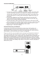
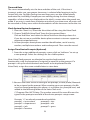
VoiceClock®
USER MANUAL & SETUP GUIDE
VOICECLOCK SERIES
TELEPHONIC TIM1
EKEEPING SYSTEM
Table of Contents
Introduction............................................................................................... Page 3
Setup Instructions.................................................................................... Page 4
How to use VoiceClock........................................................................... Page 6
Troubleshooting....................................................................................... Page 8
Specifications............................................................................................. Page 9
2
INTRODUCTION
Thank you for purchasing the VoiceClock.
Note: Please read the entire installation instructions before you begin using the
unit or attempt to connect the system to its power source and phone line(s).
The VoiceClock is very easy to configure and was activated on your SwipeClock
account before it was shipped to you. This guide will show you how to start using
the system immediately. Once the system is setup, there is rarely a need for
additional maintenance.
Your system should include the following:
•
•
•
•
The VoiceClock unit
An AC power cord
This manual and a “READ ME FIRST” instruction sheet
Separate boxed modem(s) with cords
Preventing Electrostatic Discharge Damage
Electrostatic discharge (ESD) can damage equipment and impair electrical circuitry.
It occurs when electronic printed circuit cards are improperly handled and can
result in complete or intermittent failures. To properly guard against ESD damage
and shocks, a grounding device such as a water pipe or other properly grounded
device can be used by touching the metal prior to using the unit.
Warning To avoid electric shock, ensure that an adequate surge suppressor
is used as part of the unit’s installation to the power source and that
telephone cables are disconnected when removing power from the unit.
The telecommunications lines must be disconnected before unplugging the
main power connector.
Required Equipment
The following equipment is needed to utilize the system and/or connect it for
functional use:
• A flat, unobstructed surface for positioning the system
• ESD-preventive wrist strap (optional)
• A nearby power source with surge suppressor and optional battery
backup with outlets for the VoiceClock and each modem
• At least one standard ANALOG telephone line with jacks for each modem
3
Location Suggestion
1.Place the system where it will be free from dirt, dust, moisture, and spills.
2.A battery backup and surge suppressor are strongly recommended. The
system will not be able to take calls if there is power failure and these
precautions have not been taken.
3.Securing the system and all cabling in a fixed location will prevent
connectivity issues from disrupting service.
4.You do not need to have all of the available modems connected to a
phone line for the system to operate. The system will answer only those
lines that have an incoming call.
Tip: When locating a place for the unit, don’t forget to position it so that
the display is visible. Make sure the cables and cords are out of the way and
secure to prevent safety hazards.
SETUP INSTRUCTIONS
Connect Power Cords
Connect the provided power cord to the VoiceClock and then plug it into a
suitable power source.
Find an Analog Phone Line
Your VoiceClock can only be connected to standard (ANALOG) phone line(s).
It is not compatible with digital telephone systems. Connecting the system to a
digital telephone line may damage the unit and will VOID your warranty.
Digital office lines are for specific “networked” phone models and can often be
identified by their special features, such as multiple lines, an intercom, call
forwarding, hold, and voice mail.
Tip: To tell if a phone line is suitable for use with your VoiceClock, try
connecting an analog telephone handset (not a digital multi-line phone) to
the line. If you hear a dial tone and can place an outbound call, then you
have found a line that is compatible with the system.
4
Connect the Modems
1.Connect the modem-to-computer serial cable: Plug one end of the cable
into the matching connector on the back of the modem, and the other
end into the serial port on the back of the VoiceClock. Some cables have
an extra connector; if so, leave one unconnected. Tighten the screws at
both ends.
2.Connect the telephone cord: Plug one end of the cord into the LINE
jack on the back of the modem. Then plug the other end into the wall
jack just as you would a standard telephone.
3.Connect the power cube: Plug one end of the power cube into the PWR
jack on the back of the modem. Plug the other end into an electrical outlet.
4.Turn the modem on using the toggle switch on the back panel or push
button on the front panel, depending on the model.
5.Repeat steps 1-4 for each modem.
Connect the System to a Network
In most cases, you will be connecting the system using a Cat 5 patch cord
(straight-through) to connect your system to the Internet. Check with your IT
department or local computer consultant if you have questions about network
connections or are unsure how your system is configured.
Plug one end of the network cable into the network card located in the back of
the system and the other end into your network. The network card has a port
that looks like the ports on the switch/router. The network cable should click into
place when inserted properly. (Listen for the click!) NOTE: Your system may look
different from the one pictured here. The Ethernet cable/patch cord has a “bigger
plug” than a telephone cord and 8 pins that transfer data. It is a good idea to wrap
up as much of the extra cabling as possible, tie it up with a twist tie, and place it
behind the system.
5
Time and Date
The server automatically sets the time and date of the unit. If the time is
incorrect, make sure your proper time zone is selected after logging in to the
SwipeClock site. Daylight Saving time and leap years are also automatically
accounted for, including if employees are working during the time change,
regardless of what time was displayed on the clock’s screen when the punch was
made. If an entry is made from a location outside of your time zone, all entries will
be recorded as if they were within the boundaries of the time zone set for the site.
Clock System Device Assignment
1.From the Client List, select the client that will be using the VoiceClock.
2.Choose “Add/Edit VoiceClock” from the Accountant Menu.
Click on ‘Add New’ and select the VoiceClock from the drop-down list.
If you do not see an available device please contact customer support at
[email protected].
3. Answer prompts about phone number identification, social security
number, multiple transactions and combo punch. Then save the record.
Assign Time Device Prompts (Optional)
1. From the assign additional prompts screen, click on “add new” to set up
a new prompt. Select the settings for the visible options.
Note: VoiceClock prompts are identical to regular clock terminal
functionality, with the exception of assigning a wave file to the prompt. If a
prompt is set up for clock terminals and needs to be duplicated for the
VoiceClock, assign the same variable letter to store data.
2. Because the caller will be listening to the prompt, a wave (audio) fileneeds
to be assigned to the prompt. When creating your own prompts, the file
must be named promptx.wav where x is a number (ex: prompt8.wav) and
added to the following folder of the VoiceClock unit:
C:\Program Files\MC2\Voice. The number name of the wave file must be
typed in the prompt wave field of the device prompts setup screen.
Prompts 1-7 are already created and available:
prompt1 = instructions
prompt5 = tips
prompt2 = department
prompt6 = net
prompt3 = job
prompt7 = gross
prompt4 = location
6
Test your VoiceClock
You must verify that you have connected your analog phone line(s) to the system
and the power supply is delivering power to the unit before you can do anything
else.
1.Plug the unit into a suitable power source (surge suppression and
battery backup are advised).
2.Turn the unit on and wait until the display indicates the system is ready.
3.Call the phone number you have assigned to one of the modems. You
should hear a standard greeting.
TEST RESULTS:
Success:
If you receive a request by the system to “enter your User ID” the modem is
properly connected. Repeat steps 1 through 3 for each modem you have
connected if the line has a unique phone number.
Does Not Answer Line:
This usually means that either the phone line is disconnected or the phone
line is currently in use. Check to make sure the system can receive an
inbound call on the phone line that it is connected by attaching a phone to
the other port on the modem.
Tip: You can monitor the status of a call by listening in on the other port
with a telephone connected to the extension.
HOW TO USE VOICECLOCK
1. Dial the given phone number and listen for the greeting. Choose to
clock IN or OUT (which is the 1 or 2 key on the keypad). The clock will
confirm the punch. If prompts are active, the prompt will then be heard
and data will be gathered from the caller.
2.Punch data is transferred to the server through the network connection
once every minute.
3.Punches are then visible on the time cards, which are accessible though
the online timekeeping system.
7
TROUBLESHOOTING
Your VoiceClock has been designed so that no additional maintenance should be
needed. However, at times, hiccups do occur and may require some of your
attention.
1.Problem definition - Define the problem as precisely as possible. What
specifically is happening when the problem occurs and what is the overall
problem? Is it a problem with the phone lines, computer system or
browser software? Is it internet related?
2.Gather information - When did the problem occur? Did anything
change? What error messages are you receiving, if any? What software
or hardware is involved? Were you doing anything when the problem
occurred? Is the problem reproducible? Does it happen intermittently or
all the time?
3.Narrow it down - Try to remove variables from the equation by
“dividing and conquering”, a technique often used in electronics to
resolve problems. This means breaking things down into bite-size pieces
until the piece is small enough that the fix can more easily be found.
The fix is often very simple and takes a minute to resolve once the problem
has been identified. Other problems can obviously be far more
complicated but by systematically troubleshooting following the steps
above problems can generally be resolved.
8
SPECIFICATIONS
NameDescription
System Specifics
7.9”(H) x 10.6”(D) x 13.2”(W)
Storage Drive
40 Gigabytes
Front Panel
LCD Monitoring Display
Serial Ports
Based upon count of phone lines ordered
Line Count Models
3, 6 & 12 line models (modem 3 packs are available)
Phone Line Requirements
Lines should be configured to pass Caller ID to the
system. Standard Analog lines are used in a
rotation for multiple line systems.
Voice Prompts
Uses Prerecorded or custom .WAV files for voice prompts.
Power Supply
300Watt Smart Power or greater
Recommended UPS battery backup (not included)
Warranty requires a surge suppressor (not included)
Weight
10/12.3 lbs (net/gross) + modems
Package Includes
1 Configured Case
VoiceClock Monitoring Software
1 Power Cord
Modems / Serial devices
1 User Guide
SwipeClock License based upon modem cont.
9
10
11
VoiceClock Setup Guide
The company distributing this product does not accept
liability or responsibility for inaccurate or missing information within this manual. Any and all content within
this document is subject to change and may be updated
at any time without notice.
Copyright 2014
Printed in the USA 04/24/2014
12