1
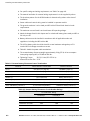
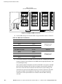
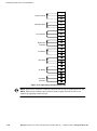
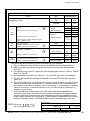
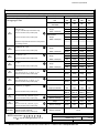
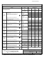
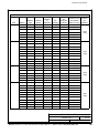
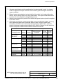
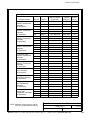
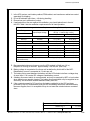
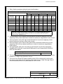
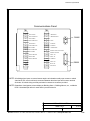
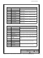
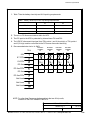
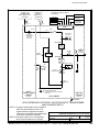
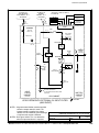
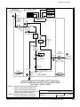
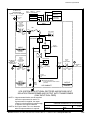
Customer Information
Table O. Communication Panel Inputs and Outputs
TB1 Pin #
Name
1
BLDG ALARM 1
2
BLDG ALARM 1 RTN
3
BLDG ALARM 2
4
BLDG ALARM 2 RTN
5
BLDG ALARM 3
6
BLDG ALARM 3 RTN
7
BLDG ALARM 4
8
BLDG ALARM 4 RTN
9
BLDG ALARM 5
10
BLDG ALARM 5 RTN
11
BLDG ALARM 6
12
BLDG ALARM 6 RTN
Description
Programmable UPS alarm. Activated by a remote
contact closure.
Programmable UPS alarm. Activated by a remote
contact closure.
Programmable UPS alarm. Activated by a remote
contact closure.
Programmable UPS alarm. Activated by a remote
contact closure.
Programmable UPS alarm. Activated by a remote
contact closure.
Programmable UPS alarm. Activated by a remote
contact closure.
Table P. Communication Panel Inputs and Outputs
TB2 Pin #
Name
1
REMOTE EPO
2
REMOTE EPO RTN
Description
Contacts used to activate remote EPO of UPS.
3
4
ON INV
5
ON INV RTN
6
ON BYPASS
7
ON BYPASS RTN
8
BATTERY CONTACTOR
CLOSED
9
BATTERY CONT RTN
10
RELAY 1 NO
11
RELAY 1 NC
12
ALARM RTN
13
RELAY 2 NO
14
RELAY 2 NC
15
NOTICE RTN
Contacts used to indicate On Inverter status of UPS.
Contacts used to indicate On Bypass status of UPS.
Contacts used to indicate UPS Battery Contactor is
closed.
General purpose NO and NC relay contacts.
General purpose NO and NC relay contacts.
DESCRIPTION:
DRAWING NO:
REVISION: G
INSTALLATION NOTES
SHEET: 16
164201118−1
DATE:
of 19
020604
EATON Powerware® 9315 UPS (300–500 kVA) Installation Manual S 164201118 Rev H www.powerware.com
A−17