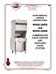
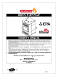
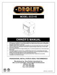
1
Adjusting the Projected Image After installing, connecting and powering up your RPSB components, you must perform a few simple adjustments to ensure that the image from your computer is correctly projected onto the SMART Board. To adjust the projected image, three procedures are necessary: 1. Ensure that computer and projector resolutions match at the software level. 2. Adjust the angle of the small front mirror. 3. Adjust the position of the projector itself. NOTE: The large rear mirror in every RPSB model never needs adjustment. The angle of this mirror is entirely dictated by your choice of projector and is precisely set at our factory. 1. Matching Computer Resolution to Projector Resolution It is very important that computer and projector resolutions match. If they don't match, the onscreen image will not properly fill the SMART Board screen. You must first ensure that the projector is set to its optimal image resolution. Refer to your projector’s manual for the true resolution of your projector, and reset it if necessary. While these instructions may indicate that resolutions other than the optimal one are permitted, you should not set the resolution to any of these other settings. For example, if the projector’s true resolution is 800 x 600, but it's also capable of displaying at 640 x 480, set both the computer and the projector to the true resolution 800 x 600. IMPORTANT: If the resolution of the projector is set to anything other than the true resolution, or if the computer and projector resolution do not match, you may be unable to see all of the image on the SMART Board, or the image that appears may be too small to properly fill the SMART Board, even with further adjustments. To set your Windows 95 computer resolution to match the projector resolution: 1. Click the Windows 95 Start button and then point to Settings. NOTE: You may need to perform the following procedure via your computer monitor, as resolution differences can distort the image on the Board to the point where visibility is impaired. 2. Point to the Control Panel folder and release the mouse button. The Control Panel directory of folders will appear. 3. Double-click on Display. The Display Properties dialog box will appear. 4. Click on the Settings tab. 5. In Desktop area, click and drag the sliding bar to adjust the pixel setting to match the resolution of your projector. 6. Click the Apply and OK buttons. 7. Restart your computer, if required. RPSB 1800/1802 Installation Guide 35 To set your Windows 3.1 or 3.11 computer resolution to match the projector resolution: 1. Go to the Windows 3.1 Program Manager. 2. Double-click on the Main icon. 3. Double-click on the Windows Setup icon. 4. Select Change System Settings from the Options menu. The Change System Settings dialog box will appear. 5. Scroll through the Display drop-down menu and select the setting that matches the resolution of your projector. 6. Click OK. 7. Restart your computer, if required. To set your Macintosh computer resolution to match the projector resolution: 1. Click on the Apple menu. 2. Click on Control Panels. 3. Select Monitors. The Monitors dialog box will appear. 4. Click the Options button. 5. Go to the Select a monitor setting box and select the resolution setting that matches the resolution of your projector. 6. Click OK. 2. Adjusting the Small Mirror While making adjustments, check both the reflection in the small mirror and the actual image on the screen. For an optimal image, the reflection must be in the center of the small mirror and each side must be symmetrical. The projector should be perpendicular to the small mirror. When you're finished, tighten the straps that secure the projector (if appropriate) or bolt the projector to the platform. WARNING: Never look directly into the projector lens. S m all M irror R e fle ctio n Small Mirror and Image Reflection 1. Adjust your image so that it is smaller than the SMART Board screen. 2. Access the small mirror from the cabinet's front doors and loosen the thumbscrews on either side of the mirror enough to allow the mirror to be moved (with some friction remaining). 36 RPSB 1800/1802 Installation Guide M ove Image Up or Dow n S m a ll M irro r (a cce ss from fro nt d oo rs) S M A R T B oa rd Im a ge L oo se n Th um b scre w S m a ll M irro r S ide V ie w 3. Gently push the mirror away from you, from the bottom. 4. Watch the SMART Board overhead as you push: If the projector is turned on, you'll see the image slide up the screen. Pulling the mirror towards you will cause the image to move down the screen. Stop moving the mirror when the image appears to be centered on the screen. The image should not cover the entire screen. 5. Use the projector's zoom lens to zoom out until the image squarely covers the entire screen. 6. Tighten the thumb screws on both sides of the mirror to hold it in place. NOTES: • Do not overtighten these screws. Also, be careful not to forcibly move or twist the mirror while tightening the screws. • Adjust the position of the cables so they do not block the projector light path. If you see cable shadows on the screen when the projector is turned on, make further adjustments to the cable positions. 3. Adjusting the Projector You must make a few final adjustments to the projector to ensure a focused image that fits within the bezel of your SMART Board at the top and bottom, with a margin of approximately 3/8" on both right and left sides. Try each of the following procedures in turn, always using small, slow movements. Look up and observe the effect on the image projected on the SMART Board as you make each fine adjustment. NOTE: The 3/8" margin described above is an optimal measurement. Alignment can vary: in some instances, the image can fill the entire screen; in others, the margin can be greater than 3/8", but be perfectly satisfactory as long as it's even on all sides. To move the image from side to side, shift the platform top slightly from right to left. Loosen the four screws that secure the top to the platform base, then shift the platform until the image is centered properly. RPSB 1800/1802 Installation Guide 37 Im age Side-to-Side A djustm ent Tighten the screws that secure the top of the platform when the correct position is achieved. Tilt the projector platform to make the image level. Roll Adjustm ent - L oo sen b oth kno bs - Tilt platform - Tigh te n bo th kn ob s to m ainta in n ew po sitio n Use the zoom lens or move projector to expand/contract the image. 1. Use the projector's zoom lens to adjust image size. Zooming in or out may be sufficient to expand or contract the square of light to fill the SMART Board. Im age Size Adjustm ent M ove pro je ctor on p la tfo rm o r use proje ctor zoo m KEYSTONING NOTES: • If the image is keystoned along the sides − that is, the side margins are different widths (see the figure on the next page) − you may need to raise or lower the front or back of the projector slightly. • If the image is keystoned along the top or bottom (the sides of the image are not of equal length), the projector is not positioned properly at a right angle to the small front mirror. You may need to move only the back of the projector side to side to correct the image. 2. You may be able to make minute adjustments to the projector’s position with the projector’s built-in software, using a remote control or buttons on the projector. Refer to your projector’s manual for details. 3. Repeat the procedures described above as necessary. 38 RPSB 1800/1802 Installation Guide Completing the Installation To complete the installation of your RPSB 1800 or 1802, you must replace the rear access panel and lower baffle door you removed earlier, install the SMART Board Software on the internal computer, and, finally, configure and orient the SMART Board. To integrate the video camera shelf that comes with the RPSB 1802 (or has been ordered for your RPSB 1800), turn to the video camera integration instructions in Appendix C. Replacing the Rear Access Panel and Lower Baffle Door NOTE: If the design of your projector is such that it protrudes beyond the rear of the cabinet, you will not be able to replace the rear access panel. L o w e r B a ffle Door R e a r A cce ss P a n e l 1. Use the 1/8" Allen key to replace the four screws that attach the rear access panel and lower baffle door to the cabinet. 2. Tighten the screws. Installing the SMART Board Software Every RPSB comes with two pieces of software: the SMART Board driver and SMART Notebook. These two programs are combined in a single executable called SMART Board Software. The SMART Board driver activates your RPSB, allowing you to use your finger as a mouse, annotate over an application with electronic ink, and use the new generation of Board-aware applications. SMART Notebook allows you to create, organize and save notes on either a Rear Projection SMART Board or at your workstation and then send those notes to a printer. A full range of annotation tools are available to enable you to create a variety of annotations. You can also use Notebook commands to export and import both graphics and text to and from other Windows applications and your Notebook file. Refer to the SMART Board User’s Guide and the online Help for each program for comprehensive instructions on their use. RPSB 1800/1802 Installation Guide 39 Windows 95/98 and Windows NT 4.0 Installation 1. Close all applications. 2. Insert the SMART Board Software disk into drive A. 3. From the desktop, click on Start, Run. 4. Type A:\Setup 5. Select OK. 6. Follow the remaining instructions as they appear on your screen. Macintosh Installation Switch on your Macintosh computer and install the SMART Board Software disk as follows: 1. Insert the SMART Installation disk into your floppy drive. 2. Double-click the SMART Installer icon. The SMART Installer window appears. 3. Click the Continue button to proceed with the installation. 4. You must now decide if you want a Normal Install or a Custom Install. The Normal installation includes both SMART Notebook and the SMART Board driver programs. 5. Click the Install button to install both the SMART Notebook and SMART Board driver programs. 6. Click the Custom button to install either SMART Notebook or SMART Board driver. 7. If you chose the Custom Install, select which of the two programs you want to install. 8. Follow the on-screen installation instructions to select a destination folder for the SMART Board Software. Configuring and Orienting the SMART Board After installing the SMART Board Software, you must perform two procedures: configuring and orienting the SMART Board. Configuring the SMART Board involves specifying which COM port your computer uses and whether or not you are using a projector with the SMART Board. To use a SMART Board with a projector, you must orient the computer image on the SMART Board to ensure that the Board accurately tracks your finger or a Pen Tray tool. Orienting the SMART Board involves pressing on orientation points displayed on the screen. If the projected image becomes misaligned, you must perform the orientation procedure again. To select a COM port for the SMART Board: 1. Choose Select Ports from the Board menu (either from the SMART Board driver window or right-mouse click on the SMART Board System Tray icon). or Press the Select Ports button on the initial Board driver window. The Check SMART Board Connections dialog box will appear. 2. Ensure all hardware elements are securely connected. 3. Press the Next button. The Pick a Port dialog box will appear. 40 RPSB 1800/1802 Installation Guide 4. If you know the COM port that is connected to your SMART Board, select it from the list of ports provided. or If you are not sure which COM port to select, press the Detect SMART Boards button to initiate automatic SMART Board detection on local ports. At this point, you should close any other open programs and save any unsaved work, in the event that your computer locks up during this process. The Auto Detect program will inform you which COM port is connected to your SMART Board. NOTE for Macintosh Users: The Macintosh Pick a Port dialog box offers Modem Port and Printer Port selections. Click on the appropriate selection. Otherwise, proceed as outlined below, clicking Detect SMART Boards to initiate the automatic detection of your Modem or Printer ports. 5. Press the Next button. The Finished dialog box will appear. 6. Press the Done button. The Ready Light on the Pen Tray will be illuminated. If your hardware configuration changes, this configuration procedure will need to be performed again. To orient the SMART Board: 1. Select Orient Board from the Board menu (either from the SMART Board driver window or right-mouse click on the SMART Board System Tray icon). or Press the Orient SMART Board button on the initial Board driver window. or Click or press twice on the SMART Board icon in the System Tray. or Press the two Pen Tray buttons simultaneously (holding for at least one second). The Pick the Orientation Precision dialog box will appear. 2. Preview the three orientation levels − Quick, Standard and Fine − by clicking on the circle next to each heading. Notice that the number of crosses in the miniature SMART Board screen to the left of these headings increases as you move down the list of headings. The three orientation levels are described briefly below. • The Quick orientation requires only 9 clicks to complete and is well-suited for fast orientations. • The Standard orientation requires 20 clicks and provides a level of accuracy suitable for most systems. • The Fine orientation involves clicking on 80 individual crosses. While the Fine setting is the most time-consuming to complete, it is recommended for higher-resolution systems that may require a more precise orientation. 3. Once you have determined the orientation level you prefer, select it by clicking in the appropriate circle. 4. Click the Next button. RPSB 1800/1802 Installation Guide 41 A large gray rectangular image will almost entirely fill the SMART Board screen. This screen will contain the number of crosses associated with the orientation level chosen. 5. Follow the on-screen instructions, pressing your finger squarely on the yellow center of each red cross, in the order specified by the large white arrow. To begin the orientation, press on the cross highlighted in red at the upper-left corner of the screen. You will hear a beep and the next cross in the series will be highlighted in red. NOTE: If you press on the crosses out of sequence or inaccurately, a Bad Orientation Point dialog box will appear. To correct the bad orientation, select the OK button at the bottom of the screen using the mouse attached to your computer. This is necessary because the system has lost Board-awareness while orienting. When you have pressed on the final cross, the Orientation screen will disappear. 6. Test if the orientation was successful by moving your finger across the SMART Board. The cursor should track your finger very closely and appear directly beneath the center of your fingertip. 42 RPSB 1800/1802 Installation Guide Customer Support Contacting SMART Technical Support All SMART software includes one year of free telephone, fax, and e-mail support. Contact SMART Technical Support in any of the following ways: Toll-Free: 1.888.42.SMART Telephone: 403.228.5940 (Available 7 a.m. − 6 p.m. MST from Monday to Friday) Fax (24 hr.): 403.245.0366 E-mail: [email protected] Web site: www.smarttech.com Please provide us with information about when you purchased the RPSB, the dealer's name, your version of MS-DOS, Windows or Macintosh and SMART Board driver, and the name of the application software causing the problem, if applicable. Other SMART Contacts Sales and Marketing: toll-free at 1.888.42.SMART or telephone 403.245.0333 Fax (24 hr.): 403.245.0366 E-mail: [email protected] Our Address: SMART Technologies Inc. Suite 600, 1177 - 11th Avenue SW Calgary, AB CANADA T2R 1K9 Warranty Rear Projection SMART Boards manufactured by SMART Technologies include a one-year parts and labor warranty. Customers must return any defective merchandise to an authorized service center as directed by the reseller or manufacturer. Warranty Shipping Charges Shipping charges incurred from warranty service are paid as follows: The customer is responsible for shipping the system to the service center. SMART pays return shipping via ground service on any product returned for service within the warranty period. Any charges associated with a customer-requested rush order are billed to the customer. Following the warranty period, the customer is responsible for shipping the product to and from the service center. Read the warranty shipped with your RPSB for details. User Registration Card A User Registration Card is shipped with every RPSB. To facilitate user support and to receive news and updates, fill in and mail the card to SMART Technologies. Alternatively, you can register online at the end of the SMART Board Software installation process. RPSB 1800/1802 Installation Guide 43 Appendix A: Maintenance and Transportation Cleaning Cabinet Components and Mirrors Mirrors and cabinet components should be periodically dusted using a soft cloth. All mirrors can be lightly cleaned using a standard glass cleaner and a soft, clean cloth. The rear surface of the SMART Board is well-protected from handling by its location on the inside of the cabinet. However, if it must be dusted, or if a mark has been made on its surface, it can be wiped gently with a soft cloth and standard glass cleaner. Do not spray the glass cleaner directly onto the surface; spray it lightly on the cloth, then gently dab the back surface of the SMART Board until the marks are removed. WARNING: Do not, under any circumstances, apply isopropyl alcohol, varsol, water or acetone to the rear surface of the SMART Board. If any of these fluids come into contact with this surface, the SMART Board becomes unusable. Cleaning the Writing Surface To clean the writing surface of the SMART Board, use a standard glass cleaner. Spray the cleaning fluid on the SMART Board surface and immediately wipe with a paper towel or soft cloth. If a permanent marker has been used, try rubbing the spot with a cloth dampened with isopropyl alcohol. Then use a standard glass cleaner to thoroughly clean the surface. Preventing Damage to the Writing Surface While the SMART Board is very durable, sharp objects can scratch or cut the surface. Sharp writing instruments, such as ball point pens or fine-pointed pens, can damage the surface if enough pressure is applied. Keep these types of pens away from the SMART Board, and avoid abrasive erasers and cleaning materials. Transporting the RPSB System When you transport the RPSB, it is important to ship the cabinet in the upright position only. In addition, the SMART Board should never be laid face down. Follow the preparation procedures outlined below and the RPSB should arrive at its destination without mishap. To prepare the RPSB for transport to another room: 1. Unlock the cabinet’s casters by pushing up on the caster locks. 2. Disconnect power, communications and network cables as necessary. 3. Slide the Pen Tray shelf in and close the Pen Tray shelf door. 4. Return the rear mirror of the RPSB 1800/1802 to its original transport position: • 44 Rotate the lower baffle door until it stops. RPSB 1800/1802 Installation Guide L o w e r B affle D o o r • Remove the two mirror lock screws, and rotate the large rear mirror upwards until it stops (lifting top baffle slightly). Top B a ffle M irror R e m o ve m ir ro r-loc k s cre w s a n d ro tate m irr or u p w a rd s. • Close the top baffle, then install the mirror lock screws and the lower baffle lock screws removed during the original cabinet installation. Ensure the lower door is secured in place. Mirror-Lock screws Lower baffle lock screws To p B a ffle RPSB 1800/1802 Installation Guide 45 Removing and Reinstalling the RPSB 1800/1802 Screen You may need to remove and then reinstall the RPSB 1800/1802 screen to maneuver the cabinet through a narrow or low doorway. 1. Locate the four cap screws and lock washers at the rear of the screen in each corner. M O D 4 C able C ap Screw 4 Places SMART Board Corner Cap Screws 2. Remove the cap screws with the 3/16" ball screwdriver provided with the cabinet. Do not remove the stud below the cap screw. Lock Washer C ap Screw Stud Key H ole (S tud rests here) Removing the Cap Screws 46 RPSB 1800/1802 Installation Guide 3. Disconnect the MOD4 cable at the bottom center of the screen. 4. With the aid of another person, remove the screen from the cabinet by lifting it up, then out from the keyholes at the top of the side brackets. WARNINGS: • Do not touch the inside surface of the screen! This surface is easily smudged and very difficult to restore. You should also protect it from anything that might scratch or harm it. If you do inadvertently smudge this surface, wipe it carefully with a soft cloth and alcohol-free glass cleaner. Do not spray the glass cleaner directly onto the surface; spray it lightly on the cloth, then gently rub the back surface of the SMART Board until the marks are removed. • Do not use isopropyl alcohol, varsol, water or acetone to clean this surface! These substances will render your SMART Board unusable. 5. Remove the screen mounting bracket at the top to the cabinet, as shown in the figure below. The three mounting screws are fastened from inside the cabinet. Use the 1/8" Allen key provided with the cabinet. 6. To reconnect the SMART Board to the cabinet, re-attach the top screen mounting bracket loosely. 7. Locate the two corner studs and lift the Board up and onto the cabinet key holes via the two back studs (see diagram on opposite page for key hole and stud locations). 8. Replace the two upper cap screws and lock washers previously removed from the corners. 9. Once all screws are aligned, tighten the cap screws and upper bracket screws securely. TIP: You may need to lift the Board slightly to align the four cap screws to their appropriate holes. M ounting B racket M ounting B racket S crew s (center and both sides) Removing the Mounting Bracket RPSB 1800/1802 Installation Guide 47 Appendix B: A Quick Guide to RPSB Use These steps can be followed once the RPSB has been set up and the SMART Board Software installed. Starting up the Board ¾ If no image is visible on the SMART Board… begin from step 1. ¾ If an image is visible on the SMART Board… begin from step 2. If the red light on the power switch is on: If the red light on the power switch is off: 1. Use the projector remote control to turn the projector bulb on. 1. Turn the power switch on. The computer’s desktop will appear on the SMART Board screen. Touch the SMART Board: If a cursor appears and it tracks the movements of your finger, go to the topic “Navigating Around the SMART Board” on the next page. If the cursor fails to track your finger movements, continue from step 2 below. The projector, computer and other devices plugged into the power bar will start up, and the computer’s desktop will appear on the SMART Board screen. Touch the SMART Board : If a cursor appears and it tracks the movements of your finger, go to the topic “Navigating Around the SMART Board” on the next page. If the cursor fails to track your finger movements, continue from step 2 below. 2. Use the mouse to double-click on the SMART Board icon on the desktop image you see on the SMART Board screen. The initial SMART Board window will appear. 3. Wait for the SMART Board to initialize. The Ready light on the Pen Tray will come on and remain on. 4. Minimize the SMART Board window by touching the in the top right portion of your menu bar. ¾ 48 minimize button located If you are able to minimize the SMART Board window by touching the minimize button, then the SMART Board driver is in projected mode. RPSB 1800/1802 Installation Guide ¾ If you are unable minimize the SMART Board window by touching on the screen, you must put the software in projected mode so that the Board will respond to your contact. To put the SMART Board in projected mode: • Use the mouse to select Configure Board from the Board menu. • Click the box beside SMART Board has a projector. • Click OK. The Board will now be touch-sensitive. You can use your finger to minimize the SMART Board window on-screen. Navigating Around the SMART Board You can use your finger to activate windows or program elements simply by touching icons on the screen. You can see the cursor appear directly beneath your finger. Each press of the finger is equivalent to a left mouse click. Of course, if you prefer, you can still use your mouse to perform navigation and activation. NOTE: If the cursor fails to closely track your finger movements, you may need to reorient the SMART Board. Simply maximize the SMART Board driver window, select Orient from the Board menu and proceed through the orientation instructions provided on-screen. Double-Clicking To double-click on the SMART Board, press twice with your finger. Avoid lifting your finger from the surface of the Board between the first and second press of a double-press. This ensures that the two contact points are very close to each other, registering as a double-click rather than as two discrete contact events. Starting up SMART Notebook Use your finger to double-click on the SMART Notebook icon on your screen. A blank Notebook page will appear on screen. You can use any of the styluses in the Pen Tray to write on the SMART Board, or select a tool from the toolbars menu and use your finger to write or draw on the Notebook screen. For more information about using Notebook, refer to the SMART Board User’s Guide or to the Notebook online Help. Turning off the SMART Board between Meetings Use the projector’s remote control to put the projector in standby mode. This will activate the projector’s fans to cool and shut off the lamp. CAUTION: Each projector is different, so you should read the manual supplied with your particular projector to learn how to put the projector in standby mode. You can leave the rest of the system powered up between meetings. Turning off the SMART Board at the End of the Day 1. Shut down any programs you have been using. RPSB 1800/1802 Installation Guide 49 NOTE: You do not need to shut down the SMART Board driver program. 2. Exit the operating system. 3. Use the projector’s remote control to put the projector in standby mode. This allows the lamp to cool before final shut down. Your projector manual may recommend that you wait a couple of minutes for the projector’s fans to cool the lamp. 4. Turn the on/off switch at the front of the cabinet to “off”. This will shut down the computer, the projector and any other devices connected to the power bar. 50 RPSB 1800/1802 Installation Guide Appendix C: Integrating a Video Camera and Shelf To integrate a video camera and shelf, you must first gain access to the cabinet interior by removing the Rear Access Panel and Lower Baffle Door as described on page 8 of this guide. You do not need to remove the SMART Board screen. NOTE: The camera shelf may be mounted on either side of the cabinet. We recommend that you mount it opposite the optional Flip-Up Shelf. To integrate a video camera and shelf: 1. From inside the cabinet, push out the Hole Cover found on the top side of the cabinet near the screen. From the outside, remove the three Shelf Mounting Screws around the Hole Cover using the 1/8” Allen key provided. Keep these screws for use in Step 2. 2. Place the Camera Shelf over the large hole and fasten it to the cabinet with the three Shelf Mounting Screws removed in Step 1. 3. If your camera has a standard 1/4-20 camera mount, use the 1/4-20 Screw provided to mount the camera through one of the series of holes on top of the Camera Shelf. Use the 3/16” ball driver which came with the cabinet. Depending on the height of the camera’s feet, you may need to use some of the Washers provided to adjust the height of the screw. 4. Connect the camera cables to the camera. Route the cables beneath the shelf and through the large hole in the side of the cabinet. 5. From inside the cabinet, find the optimal route to keep the wires snug to the inside of the cabinet. Use the Adhesive Cable Ties provided. If necessary use the extension cables provided to connect to your computer. 6. Install the Camera Shelf Light Baffle with the two screws provided. Use the 1/8” Allen key provided. 4. C am era Ca bles 2. Sh elf M ou nting Screw s a nd C am era She lf 3. 1 /4 -20 M o un ting Sc rew a nd W a shers 6. C am era She lf L ig ht Baffle 5. Ad he sive 1 . C ab le Tie s H ole C over C ut-A way View of C abinet RPSB 1800/1802 Installation Guide 51 Glossary Aware: See SMART Aware. Baffle: An obstruction that prevents the flow of light, noise, etc. Baffles are placed in several locations on the RPSB to keep external light from affecting the projected image inside the cabinet. Bezel: A frame. A SMART Board is an electronic whiteboard surrounded by a bezel. Board-aware applications: Applications written to specifically take advantage of the features in a SMART Board. Captive screw: A screw that is fixed on a spring to prevent it from pulling free from the material to which it is attached. Caster: A small wheel on a swivel, set under a piece of furniture to make it easy to move. The casters on RPSB's have locking tabs. COM port: Common abbreviation for communications port. A communication port is a socket on a computer to which peripheral devices (such as mice and modems) that need to communicate with the computer are connected. Hex ball driver: A screwdriver with a hexagonal-shaped head. A 3/16" hex ball driver may be shipped with an RPSB, and is used to remove screws from the back of the rear mirror to transform a system from the transport to the operating position, and back again if necessary. Alternatively, an L-shaped hex key may be shipped with the RPSB system. Keystone correction angle: The angle at which optics inside a projector have been set to compensate for distortions caused by projecting onto a surface at an angle. Mini RJ11 connector: The connector end of a MOD4 cable. A close look at a mini RJ11 connector will reveal four tiny contacts set into four slots. It may also be known as a telephone handset connector or RJ22. MOD4 cable: A flat modular cable consisting of 4 wires covered in a protective sheath. It connects the SMART Board to the Pen Tray in an RPSB unit. MOD6 serial cable: A flat modular cable consisting of 6 wires covered in a protective sheath. It connects two computer or peripheral devices to allow communication between them. It connects the Pen Tray to the computer in an RPSB system. Rear-projection mode (reversed-image mode): One of several projection modes available on most projectors. Reversed-image mode transforms the reversed image that results from projecting from behind the screen surface. Resolution: The number of displayed pixels per inch. Common resolutions are 640 x 480, 800 x 600, and 1024 x 768. RJ11-6 connector: The connector end of a MOD6 serial cable. A close look at a RJ11-6 connector will reveal six tiny contacts set into six slots. May also be known as an RJ12. Serial communications port: A general-purpose computer socket to which you can connect serial devices, including mice and modems. Serial port adaptor, 25-pin: A device that accepts an RJ11-6 connector at one end and connects to a DB-25 serial port on a computer at the other. The device allows physically different components to be connected to each other, enabling RPSB users to connect the Pen Tray to the computer’s DB-25 male serial port. 52 RPSB 1800/1802 Installation Guide Serial port adaptor, 9-pin: A device that accepts an RJ11-6 connector at one end and connects to a DB-9 serial port on a computer at the other. The device allows physically different components to be connected to each other, enabling RPSB users to connect the Pen Tray to the computer. SMART Aware: Software that automatically runs with the SMART Board driver and allows specific third-party conferencing applications, such as Microsoft® NetMeeting™ and Intel® ProShare™, to recognize tools from the SMART Pen Tray as integral software components. Aware allows you to extend the unique presentation capabilities of the RPSB to many other popular conferencing applications. SMART Board driver: The software that drives, or activates, a SMART Board. The software allows you to use your finger as a mouse, annotate over an application with electronic ink and use SMART Notebook and other Board-aware applications. Throw distance: The distance a projector must be set from the projection surface to cast a square image of a particular size. True resolution: The native resolution at which a projector has been designed to operate without software enhancement. Projectors may operate in other resolutions, but the quality of the projected image may suffer. For example, a projector’s optimal resolution may be 640 x 480 pixels (VGA), 800 x 600 pixels (SVGA) or 1024 x 768 pixels (XGA). RPSB 1800/1802 Installation Guide 53 Index Matching Computer Resolution to Projector Resolution, 29 A Adjusting the Projected Image, 29 Adjusting the Projector, 31 O Orientation levels, 37 Outline of Guide Contents, 1 B Bolting projector to the platform, 7 P C Cabinet Tools, Cables and Connectors, 2 Cleaning cabinet components and mirrors, 40 Completing the Installation, 35 Computer installation, 7 resolution, 29 switching on, 25 Connecting Internal Wiring, 9 Customer Support, 39 D Pen Tray shelf, 1 Pick the Orientation Precision (dialog box), 37 Projector adjustment, 31 bolting to platform, 7 installation, 6 lens placement, 33 recommended brightness, 1 resolution, 29 start-up, 44 strapping in place, 6 switching on, 25 throw distance, 34 Pulling out the Pen Tray shelf, 7 Display Source Switch, 1, 27 Q F Quick orientation, 37 Quick Setup Guide, 1 Fine orientation, 37 Front door adjustment, 2 R G Glossary, 48 I Installing the Computer, 7 Installing the Projector, 6 Installing the RPSB 1600 and 1602, 1 Installing the SMART Board Software, 35 Integrating a Video Camera and Shelf, 47 K Keyboard installation, 8 Keystone Correction Angle, 34 Keystoning correcting the problem, 32, 34 problems, 34 Keystoning problems, 32 M Maintenance and Transportation, 40 54 RPSB Installation Guide Ready light, 44 Rear mirror repositioning, 3 Rear Projection SMART Board 1800/1802 described, 1 Rear-projection mode, 25 Removing and Reinstalling the RPSB 1800/1802 Screen, 42 Removing the Lower Baffle Door and Rear Access Panel, 5 Replacing the Rear Access Panel and Lower Baffle Door, 35 Repositioning the Rear Mirror, 3 RPSB 1800 Computer Connections, 12 RPSB 1800 Connection Procedures, 12 RPSB 1800 Power Connections, 16 RPSB 1800 Projector Connections, 14 RPSB 1800 VCR/DVD Connections, 15 RPSB 1802 Computer 1 Connections, 20 RPSB 1802 Computer 2 Connections, 26 RPSB 1802 Connection Procedures, 20 RPSB 1802 Power Connections, 24 RPSB 1802 Projector Connections, 22 RPSB 1802 VCR/DVD Connections, 23 S Selecting a COM Port for the SMART Board, 36 Setting Up the Keyboard, 8 Setting Up the RPSB 1800/1802 Cabinet, 2 Sliding projector platform, 6 Small mirror repositioning, 30 SMART Board centering the projected image, 31 cleaning, 40 configuring, 36 damage prevention, 40 maintenance, 40 navigation, 45 orienting, 36 shut-down sequence, 45 start-up, 44 SMART Board driver, 1, 35 SMART Meeting Pro, 1 SMART Notebook, 1, 35, 45 start-up, 45 SMART X-Port 10, 1 Software Installation Macintosh, 36 Windows 95, 36 Standard orientation, 37 Strapping the projector, 6 Supplied Software, 1 Switching on the Projector and Computer, 25 T Table of Cabinet Connections RPSB 1800, 11 RPSB 1802, 18 Throw Distance, 33 Transporting the RPSB, 40 U User Registration Card, 39 Using the RPSB, 44 V Variables in Projector Design, 33 Video camera shelf installation, 47 W Warranty, 39 warranty shipping charges, 39 Wireless keyboard set-up, 8 Wiring Diagram RPSB 1800, 10 RPSB 1802, 17 RPSB Installation Guide 55 Technologies Inc. Suite 600, 1177 - 11th Avenue SW, Calgary, AB CANADA T2R 1K9 Support: 1.888.42.SMART Tel. 403.228.5940 Fax 403.245.0366 E-mail: [email protected] www.smarttech.com RC8-MAN-00 REV B Printed in Canada