1
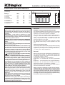
Wall Mounting
Thermostat Operation
IMPORTANT – The wall brackets supplied with the appliance
must be used. The heater should be positioned observing
the minimum clearances stated around the heater - see
Fig. 1.
The heater is fitted with an adjustable thermostat enabling
the room temperature to be controlled by adjusting the setting
accordingly. The * setting represents a room temperature of
approximately 5°C and may be used for protection against
frost. Higher temperature settings range from 1-6 (max.)
creating a room temperature of approximately 30°C.
DO NOT locate the heater immediately below a fixed socket
outlet or connection box.
1.
2.
3.
4.
Remove wall mounting bracket from the back of the
heater by depressing the spring latch at the top of
each bracket - see Fig. 2.
Fix the wall bracket securely to the wall through the
four screw holes provided.
Present the heater to the wall bracket, and engage
lower slots in the back with bracket.
Raise the heater to upright position and push the
heater onto brackets to engage top latch.
A neon indicator light glows when the appliance is actually
heating.
Switch on the heater and turn the thermostat knob to mark 6
opposite the indicator mark (located on centre right of the
knob - see Fig. 4 & 5), and set selector switch to full heat
output to warm the room rapidly. When the room temperature
has reached the desired level, turn the thermostat knob back
slowly until the thermostat just clicks off. The heater will then
maintain the room temperature at the chosen level, provided
that the correct size of heater has been selected for the room
to be heated.
NOTE – Should your heater fail to come on when the
thermostat knob is at a low setting, this may be due to the
room temperature being higher than the thermostat setting.
Operation - TI and TX Timer Models
255
MIN
Control of Output and Temperature (see Fig. 5)
Fig. 2
The slide switch on the timer unit controls the electricity
supply to the heating elements on TI and TX models.
The switch marked I - II (half heat – full heat) provides a
choice of output as desired.
Access to the controls
The controls cover (see ‘x’ in Fig. 1) on your heater has a
latch which may be locked shut if desired using a small
bladed screwdriver - see Fig. 3.
To open the cover insert the blade of the screwdriver in the
small slot and rotate a quarter of a turn clockwise to
disengage the latch. The cover may then be hinged back
towards the wall for access to the controls.
Fig. 5
Thermostat Operation
- see above.
Using the Timer
The heater must be connected to the electricity supply for the
timer to operate. Set the timer by rotating the dial clockwise
until the correct time of day is indicated opposite the datum
mark (located at centre front of the timer - see Fig. 5).
Fig. 3
Operation - Thermostat only models
‘OFF’ Position
Control of Output and Temperature (see Fig. 4)
Set the timer switch to position. The timer operates but the
heater will not output any heat, as the electricity supply to the
heating elements has been disconnected.
The switch marked O and I controls the electricity supply to
the heating elements. The OFF position is marked O.
The switch marked I - II (half heat – full heat) provides a
choice of output as desired.
Fig. 4
Manual Operation
position. The heater will now operate
Set the timer switch to
continuously under the control of the thermostat - see
‘Thermostat Operation’ above.