1
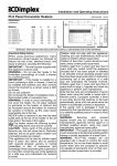
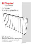
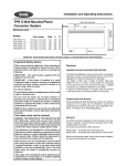
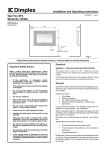
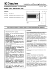
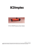
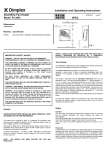
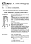
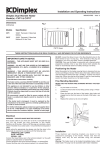
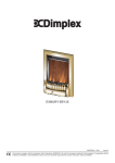
Installation and Operating Instructions
PLX Panel Convector Heaters
INDPUKP5RG Issue 0
Dimensions
(millimetres)
150
MIN
Model(s)
Watt
A
B
PLX 500/NC/TI/WTI
PLX 625/NC
PLX 750/NC/TI
PLX 1000/NC/TI/WTI
PLX 1250/NC/TI
PLX 1500/NC/TI/WTI
PLX 2000/NC/TI/WTI/TX
PLX 3000/TI/TX
500
625
750
1000
1250
1500
2000
3000
450
688
620
620
688
688
860
860
108
108
108
108
108
108
108
143
A
‘x’
150
MIN
B
430
150
MIN
Fig. 1
IMPORTANT: THESE INSTRUCTIONS SHOULD BE READ CAREFULLY AND RETAINED FOR FUTURE REFERENCE
Important Safety Advice
When using electrical appliances, basic precautions
should always be followed to reduce the risk of fire,
electrical shock, and injury to persons, including the
following:
IMPORTANT – The wall brackets supplied with the
appliance must be used.
IMPORTANT – If the heater is installed in a room
containing a bath or shower, it must be so installed that
switches and other controls cannot be touched by a
person using a bath or shower.
Do not use outdoors.
Do not locate the heater immediately below a fixed socket
outlet or connection box.
Do not cover the heater. Do not place material or
garments on the heater, or obstruct the air circulation
around the heater, for instance by curtains or pushing
furniture up against the heater, as this could cause
overheating and a fire risk.
NEVER cover or obstruct in any way the heat outlet slots
at the top of the heater or the air inlet slots in the base of
the heater.
The heater carries the Warning symbol indicating
that it must not be covered.
WARNING – THE SURFACES OF THIS HEATER CAN BE
HOT. Momentary contact with any part of the heater
should not cause injury. However, aged or infirm persons
or young children should not be left unsupervised in the
vicinity of the heater unless a suitable guard is fitted.
This appliance is not intended for use by children or
other persons without assistance or supervision if their
physical, sensory or mental capabilities prevent them
from using it safely. Children should be supervised to
ensure that they do not play with the appliance.
Note that due care and consideration must be taken
when using this heater in series with a thermal control,
a program controller, a timer or any other device that
switches on the heat automatically, since a fire risk
exists when the heater is accidentally covered or
displaced.
If the supply cord is damaged it must be replaced by the
manufacturer or service agent or a similarly qualified
person in order to avoid a hazard.
Electrical
WARNING – THIS APPLIANCE MUST BE EARTHED
The electrical installation must be carried out by a competent
electrician, and be in strict accordance with the current I.E.E.
regulations for Electrical Equipment in Buildings.
The heater is fitted with a length of flexible cable type H05VVF size 3 x 1.0mm2 on models PLX 500 - 2000 and size 3 x
1.5mm2 on PLX 3000 models, for connection to the fixed
wiring of the premises through a suitable connection box
positioned adjacent to the heater.
The supply circuit to the heater must incorporate a double
pole isolating switch having a contact separation of at least
3mm.
Supplementary Earth Bonding
Should Equipotential Earth Bonding be required the earthing
conductor in the supply cord is deemed to provide the
supplementary bonding connection (see Regulation 54703-05, 16th Edition I.E.E. Wiring Regulations).
General
The PLX Convector is designed for wall mounting on the wall
brackets supplied. It should only be operated when in the
upright position as shown.
All models are splashproof to IP24 standard.
Models PLX…TI are fitted with a 24 hour programmable
timer.
Models PLX…TX are fitted with a 7 Day programmable timer.
Models PLX…NC are fitted with no controls, for use with
external thermostatic or programming controllers.
Before connecting the heater check that the supply voltage is
the same as that stated on the heater.
Wall Mounting
Thermostat Operation
IMPORTANT – The wall brackets supplied with the appliance
must be used. The heater should be positioned observing
the minimum clearances stated around the heater - see
Fig. 1.
The heater is fitted with an adjustable thermostat enabling
the room temperature to be controlled by adjusting the setting
accordingly. The * setting represents a room temperature of
approximately 5°C and may be used for protection against
frost. Higher temperature settings range from 1-6 (max.)
creating a room temperature of approximately 30°C.
DO NOT locate the heater immediately below a fixed socket
outlet or connection box.
1.
2.
3.
4.
Remove wall mounting bracket from the back of the
heater by depressing the spring latch at the top of
each bracket - see Fig. 2.
Fix the wall bracket securely to the wall through the
four screw holes provided.
Present the heater to the wall bracket, and engage
lower slots in the back with bracket.
Raise the heater to upright position and push the
heater onto brackets to engage top latch.
A neon indicator light glows when the appliance is actually
heating.
Switch on the heater and turn the thermostat knob to mark 6
opposite the indicator mark (located on centre right of the
knob - see Fig. 4 & 5), and set selector switch to full heat
output to warm the room rapidly. When the room temperature
has reached the desired level, turn the thermostat knob back
slowly until the thermostat just clicks off. The heater will then
maintain the room temperature at the chosen level, provided
that the correct size of heater has been selected for the room
to be heated.
NOTE – Should your heater fail to come on when the
thermostat knob is at a low setting, this may be due to the
room temperature being higher than the thermostat setting.
Operation - TI and TX Timer Models
255
MIN
Control of Output and Temperature (see Fig. 5)
Fig. 2
The slide switch on the timer unit controls the electricity
supply to the heating elements on TI and TX models.
The switch marked I - II (half heat – full heat) provides a
choice of output as desired.
Access to the controls
The controls cover (see ‘x’ in Fig. 1) on your heater has a
latch which may be locked shut if desired using a small
bladed screwdriver - see Fig. 3.
To open the cover insert the blade of the screwdriver in the
small slot and rotate a quarter of a turn clockwise to
disengage the latch. The cover may then be hinged back
towards the wall for access to the controls.
Fig. 5
Thermostat Operation
- see above.
Using the Timer
The heater must be connected to the electricity supply for the
timer to operate. Set the timer by rotating the dial clockwise
until the correct time of day is indicated opposite the datum
mark (located at centre front of the timer - see Fig. 5).
Fig. 3
Operation - Thermostat only models
‘OFF’ Position
Control of Output and Temperature (see Fig. 4)
Set the timer switch to position. The timer operates but the
heater will not output any heat, as the electricity supply to the
heating elements has been disconnected.
The switch marked O and I controls the electricity supply to
the heating elements. The OFF position is marked O.
The switch marked I - II (half heat – full heat) provides a
choice of output as desired.
Fig. 4
Manual Operation
position. The heater will now operate
Set the timer switch to
continuously under the control of the thermostat - see
‘Thermostat Operation’ above.
Automatic Operation
Safety - Overheat protection
Set the timer switch to
position. The panel will now operate
during set ‘ON’ periods under the control of the thermostat.
For your safety this appliance is fitted with a thermal cut-out.
In the event that the product overheats for some reason, the
cut-out prevents excessive temperatures on the product by
cutting the power to the heater. Once the heater has cooled
down, it will reset automatically, it will continue to cycle on
and off automatically until the reason for overheating is
removed.
To set the timer’s ‘ON’ and ‘OFF’ periods:
14
Fig. 6
13
12
11
1. Using your finger tip or the tip of
a pencil, push in as many segments
as necessary around the dial,
according to the times you don’t
require heat – see Fig. 6. Each
segment pushed in switches the
heater OFF for that part of the hour.
All other segments will be ‘ON’.
Cleaning
Before commencing cleaning, unplug the heater and allow it
to cool. Disconnect the electricity supply to the appliance.
2. You can select as many ‘ON’ periods as you like, within
the 24-hour day. The settings will repeat every day until
changed.
The outside can be cleaned by wiping it over with a soft damp
cloth and then dried. Do not use abrasive cleaning powders
or furniture polish, as this can damage the surface finish.
3. To change ‘ON’ and ‘OFF’ times, simply push in any ‘ON’
segments you wish to cancel and pull out new ‘ON’
segments as required.
To release heater from the wall bracket for cleaning or
redecoration, depress latch on both brackets (see Fig. 2)
and hinge forward.
Note: On TI models each segment on the timer represents
20 mins.
After Sales Service
TX Models
TX Models are fitted with 7 day programmable timers. In all
other respects they are identical in installation and operation
to 24 hour timer operation on TI models.
1. Setting the Time
The current day and time is set by rotating the timer dial
clockwise until the correct day and time is indicated opposite
the datum mark.
2. Automatic Operation
Set the time switch to the
symbol. Select the days and
times you require the heater to come on by pulling out the
appropriate segments. Each segment represents a 13/4 hour
period for the day indicated. The timer may be set to give as
many ‘ON’ periods of any length required in multiples of 13/4
hours. The programme will repeat itself every 7 days until
changed.
The programme may be over-ridden at any time by switching
or
to
setting.
and can be reinstated by switching back to
Your product is guaranteed for two years from the date of
purchase.
Within this period, we undertake to repair or exchange this
product free of charge provided it has been installed and
operated in accordance with these instructions.
Your rights under this guarantee are additional to your statutory
rights, which in turn are not affected by this guarantee.
Should you require after sales service you should contact
our customer services help desk on 0870 727 0101. It would
assist us if you can quote the model number, series, date of
purchase, and nature of the fault at the time of your call. The
customer services help desk will also be able to advise you
should you need to purchase any spares.
Please do not return a faulty product to us in the first instance
as this may result in loss or damage and delay in providing
you with a satisfactory service.
Please retain your receipt as proof of purchase.
Energy Saving Tips
Other Energy Saving Tips for Around the Home
The energy we use to heat, light and power our homes
contributes over a quarter of the UK’s carbon emissions, the
principle contributor to climate change.
1. Lights
Around half the energy used in the home is for heating and
hot water, so using your heating system efficiently will not
only help the environment, but also save you money !
Energy efficiency tips for heating and hot water
1. Don’t set the temperature too high…
Turn off lights whenever you leave a room for more than ten
minutes.
Use low-energy bulbs wherever you can as they use less
than a quarter of the electricity used by ordinary light bulbs
and last ten times longer!
2. Cooking
Use the right size pan for the food and cooker hob.
By reducing the thermostat setting by just 1ºC can reduce
your energy use by as much as 10%. And if you’re going
away for the winter, leave the thermostat on the frost protection
setting to provide protection from freezing at a minimum cost.
Keep saucepan lids on - this enables you to turn down the
heat.
Boil water for cooking in a kettle.
2. Use it where you need it…
Set the appropriate temperature on your heaters for the room
they are in; for example, leave the thermostat on a heater in a
spare bedroom on a lower setting.
3. Use it when you need it…
Use heaters fitted with timers or linked to central controllers
to turn the heating on only when you need it and automatically
switch it off when you don’t.
4. Curtains…
Close your curtains at dusk to stop heat escaping through
the windows.
5. Windows…
Nearly 25% of heat loss can occur through poorly insulated
frames and single glazing. If you can’t afford to double glaze
all your windows, go for the rooms you heat most.
6. Treat your hot water tank...give it a jacket
An insulating jacket for hot water tanks only costs a few pounds
and pays for itself within months. Fit one that’s at least 75mm
(3") thick and you could save £10-£15 a year.
7. Water …
Use a shower if you have one to save time, money and water.
Don’t set the thermostat too high on your water heater - 60oC/
140oF is usually adequate for bathing and washing.
Put the plug in when running hot water in your sink - leaving
hot taps running is both wasteful and expensive.
Ensure dripping taps are repaired quickly. In just one day,
you could waste enough water to fill a bath.
The product complies with the European Safety Standards EN60335-2-30 and the European Standard Electromagnetic Compatibility
(EMC) EN55014, EN60555-2 and EN60555-3 which cover the essential requirements of EEC Directives 73/23 and 89/336
Glen Dimplex UK Limited
Millbrook House
Grange Drive
Hedge End
Southampton
Hampshire. SO30 2DF
UK customer help line (8.00AM – 6.00PM Mon-Fri; 8.30AM-1.00PM Sat)
Customer Services:
Republic of Ireland
Tel.
Fax.
e-mail
Tel.
0870 7270101
0870 7270102
[email protected]
01 8424833
[c] Glen Dimplex UK Limited
All rights reserved. Material contained in this publication may not be reproduced in whole or in part, without prior permission in writing of Glen Dimplex UK Limited.