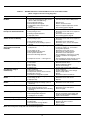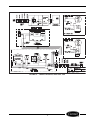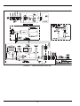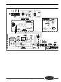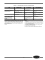
1
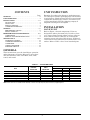
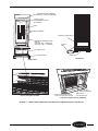
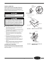
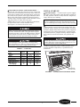
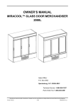
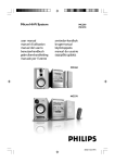
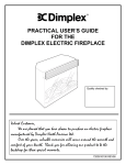
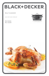
OWNER’S MANUAL MIRACOOL™ GLASS DOOR MERCHANDISER 260L - 1300L 300L a79-13 750L a79-14 1300L a79-15 Sales Office: P.O. Box 5932 Spartanburg, S.C. 29304-5932 Technical Service: 1-800-558-7627 Parts Order Fax: 1-800-262-9381 Manufacturer reserves the right to discontinue, or change at any time, specifications or designs without notice and without incurring obligations. Printed in Mexico 6-06 79BC560002-01_C CONTENTS UNIT INSPECTION Page GENERAL. . . . . . . . . . . . . . . . . . . . . . . . . . . . . . . . . . . . . . . . . . . 2 UNIT INSPECTION . . . . . . . . . . . . . . . . . . . . . . . . . . . . . . . . . . 2 INSTALLATION . . . . . . . . . . . . . . . . . . . . . . . . . . . . . . . . . . . 2-5 LOCATE UNIT. . . . . . . . . . . . . . . . . . . . . . . . . . . . . . . . . . . . . 2 LEVEL UNIT . . . . . . . . . . . . . . . . . . . . . . . . . . . . . . . . . . . . . . 4 INSTALL SHELVES . . . . . . . . . . . . . . . . . . . . . . . . . . . . . . . . 5 CONDENSATE DISPOSAL. . . . . . . . . . . . . . . . . . . . . . . . . . 5 START-UP . . . . . . . . . . . . . . . . . . . . . . . . . . . . . . . . . . . . . . . . . 6,7 PRELIMINARY CHECKS . . . . . . . . . . . . . . . . . . . . . . . . . . . 6 INITIAL START-UP . . . . . . . . . . . . . . . . . . . . . . . . . . . . . . . . 7 REFRIGERATION SYSTEM SERVICE . . . . . . . . . . . . 8-13 COMPONENTS . . . . . . . . . . . . . . . . . . . . . . . . . . . . . . . . . . . . 8 SERVICE AND TROUBLESHOOTING . . . . . . . . . . . . . . . 8 MAINTENANCE. . . . . . . . . . . . . . . . . . . . . . . . . . . . . . . . . 14,15 LAMP REPLACEMENT . . . . . . . . . . . . . . . . . . . . . . . . . . . 14 CONDENSATE REMOVAL . . . . . . . . . . . . . . . . . . . . . . . . 14 CONDENSER. . . . . . . . . . . . . . . . . . . . . . . . . . . . . . . . . . . . . 14 CABINET EXTERIOR . . . . . . . . . . . . . . . . . . . . . . . . . . . . . 14 INTERIOR SURFACE . . . . . . . . . . . . . . . . . . . . . . . . . . . . . 14 Examine all packages for damage to packaging material. Damage to external packaging may have resulted in unit damage. Check packages for all accessories and components, including legs, casters, and shelves. File a claim immediately with the shipping company if shipment is damaged or incomplete. INSTALLATION LOCATE UNIT Refer to Figure 1 for unit components. Units are designed for indoor placement only. Provide at least 3 in. of space between unit cabinet and any adjacent wall or fixture. Remove skid base by removing the retaining screws (4 hex head bolt screws). If optional casters will be used, unit must be located on flat, level surface. Refer to Table 1 for a list of standard parts. GENERAL These instructions cover the installation, operation, and maintenance of Carrier Miracool™ series glass door merchandiser units, sizes 260L, 300L, 750L, 1100L, and 1300L. TABLE 1 — STANDARD PARTS PART Refrigeration Cartridge Shelves Shelf Clips Instruction Manual Leveling Feet Lamps FACTORY INSTALLED FIELD INSTALLED X X X — — X X 260L, 300L 1 4 16 1 4 1 UNIT SIZE 750L Quantity 1 5 20 1 4 2 NOTE: Parts shown are for standard units. Quantity of shelves and clips may vary based on factory-supplied options. 2 1100L, 1300L 1 10 40 1 4 2 FLUORESCENT LAMP SIGNBOARD (SIZES 750L, 1100L, AND 1300L ONLY) UNIT DATA LABEL (INSIDE COOLER IN UPPER LEFT CORNER) SHELF PRODUCT CHAMBER CARTRIDGE COMPARTMENT INTERNAL FLUORESCENT LAMP — SIZE 750L (SIZE 260L, 300L — ALONG TOP; SIZE 1100L, 1300L — IN CENTER) SERVICE CORD FRONT GRILLE LEVELING FOOT WOOD SKID REAR VIEW FRONT VIEW a79-1 LIGHTING CORD (RIGHT CONNECTOR) WOOD SKID RETAINING SCREW, IF USED (HEX HEAD BOLT SCREW) GRILLE RETAINING SCREW POWER CORD (LEFT CONNECTOR) UNIT WITH FRONT GRILLE REMOVED FIGURE 1 — MIRACOOL™ BOTTLE COOLER UNIT COMPONENTS (Size 750L Shown) 3 LEVEL UNIT UNPLUG CARTRIDGE POWER AND LIGHTING CORDS To provide adequate condensate drainage and proper door alignment and operation of unit, the unit cabinet must be level. Leveling feet are factory installed. Remove refrigeration system cartridge for easier access to back feet. Before servicing unit, disconnect electrical service. On sizes 1100L and 1300L, turn disconnect switch (located on power cord) to the OFF position. Failure to disconnect electrical service could result in electrical shock and cause personal injury or death. a79-2 TO REMOVE CARTRIDGE 1. After disconnecting the unit from the power supply, remove the grille retaining screw located in the upper-most part of the grille. (See Figure 1.) 2. Lift the grille up and away from the unit. 3. Unplug the power supply and lighting supply cords located in the front of the cartridge (Figure 2). 4. Using a pair of wire cutters, cut wire tie that secures lifting rods at center of front base rail. (See Figure 2.) 5. Take hold of the end of each lifting rod and rotate each approximately 90-degrees upward so that they are nominally vertical (Figure 3.) The cartridge should be disengaged from the cabinet and resting on the base of the cabinet assembly. Handling holes are located on either side of the cartridge near the top and along the side of the cartridge (Figure 4). Grasp the cartridge by these holes and slide the unit forward from the cabinet until the cartridge is free. Use caution to ensure that power and electrical cords do not get pinched between the cartridge and cabinet while removing cartridge. CUT WIRE TIE THAT SECURES LIFTING RODS TO BASE FIGURE 2 — PREPARE CARTRIDGE FOR REMOVAL CARTRIDGE POWER AND LIGHTING CORDS TO LEVEL UNIT — The door is equipped with gravity assisted cams and will not function properly without proper leveling of cabinet. Adjust feet using adjustable wrench so that unit sits approximately level to floor and door closes properly. For best door operation, adjust leveling feet so that cabinet has a 1/16-in. rake or slant from front to back. Optional casters are available to replace leveling feet. a79-3 FIGURE 3 — ROTATE LIFTING WIRES IN DIRECTION SHOWN NOTE: If casters are not used, local codes may require cabinet to be sealed around the perimeter of the cabinet base. Consult local sanitation codes. Use only sealant material approved for this use, such as Dow Corning #732. PULL THE CARTRIDGE USING THE HANDLING HOLES ON SIDES a79-4 FIGURE 4 — REMOVE CARTRIDGE 4 INSTALL SHELVES TOP TAB FULLY INSERTED INTO SLOT Product shelves and a bag containing shelf support clips are packed inside the unit. Refer to Table 1 to verify quantity of shelves and shelf supporting clips. Bottom shelf must be placed on interior floor and should be inserted into the two retainer clips provided at the rear corners of the unit floor. BOTTOM TAB FULLY SEATED Improper shelf clip installation may cause shelf and/ or product to fall which could result in personal injury or damage to the unit. IMPROPERLY INSTALLED CLIP (UPSIDE DOWN) PROPERLY INSTALLED CLIP RETAINING TAB Do not overload the shelves. The unit is designed to use all the shelves provided, installed in equally spaced configuration. Failure to install shelves correctly could result in personal injury or damage to the unit. If fewer shelves or a different installation configuration is desired, contact the manufacturer to ensure that shelf overloading will not occur. TOP TAB SHELF CLIP TO INSTALL SHELVES — Refer to Figures 5 and 6. 1. Determine proper location for shelf clips. Refer to the numbers on the pilaster to ensure that all clips are properly located. 2. Insert top tab of the shelf clip into the desired hole of the pilaster. The retaining tab should be facing upward as shown in Figure 5. 3. Rotate the clip downward and insert the bottom tab into the appropriate hole on the pilaster. If necessary, squeeze the clip slightly during installation. 4. Install all remaining clips as described above. 5. Install shelves onto clips so that the product retention bar is facing upward. Be careful not to dislodge clips during shelf installation. 6. Shelves must be placed so that the retaining tab on the shelf clip captures the shelf as shown in Figure 6. 7. Before loading the shelf, ensure that the shelf is resting on each of 4 clips and that the clips are installed as shown in Figures 5 and 6. a79-5 BOTTOM TAB FIGURE 5 — SHELF CLIP INSTALLATION PILASTER SHELF RETAINED BY TAB a79-6 PRODUCT RETENTION BAR FIGURE 6 — PROPER INSTALLATION OF SHELF ON CLIP CONDENSATE DISPOSAL The evaporator drain pan is located in the base of the cartridge. Airflow in cartridge compartment hastens condensate evaporation so that external drain plumbing is not required. 5 START-UP To achieve proper lamp engagement, rotate the lamp 90 degrees from its insertion position until it snaps or clicks into place. On units without safety shields, visually verify proper lamp installation by checking the identification mark on the end of the bulb. If the bulb has been properly installed, the mark will be centered between the “halves” of the lamp holder. Refer to Figure 7. On units with safety shields, the identification mark cannot be seen. (See Figure 8.) Verify manually that the lamp has been rotated and locked into place. PRELIMINARY CHECKS BI-PIN FLUORESCENT LAMP INSTALLATION/ VERIFICATION — Before applying power to the unit, verify that all lamps have been properly installed and are fully engaged in the lamp holders. Sizes 750L, 1100L, and 1300L have 2 lamps, one in the signboard and one inside the cooler. Sizes 260L and 300L have one lamp inside the cooler. Improperly installed lamps may cause damage to the lighting circuit. Carrier will not be responsible for equipment or component failures or other damages or losses that arise as a result of improper lamp installation. a79-7 BI-PIN LAMP END IDENTIFICATION MARK Properly installed lamp without shield. Verify identification mark is positioned as shown. FIGURE 7 — CHECK INSTALLATION OF LAMP WITHOUT SAFETY SHIELD PINS MAY NOT BE VISIBLE IN ACTUAL INSTALLATION Properly installed lamp with shield. Requires manual verification that lamp has been rotated and locked into place. a79-8 Improperly installed lamp with shield. Note that pins have not achieved full 90° rotation. FIGURE 8 — CHECK INSTALLATION OF LAMP WITH SHIELD 6 ELECTRICAL SUPPLY AND CONNECTIONS — Check to be sure that the electrical service to the unit meets all local and national electrical codes. Unit electrical data is shown in the unit data label, located on the inside of the cabinet in the upper lefthand corner. Review this label before initiating electrical service. Voltage range of power supply to unit should be 105 to 125 volts. Refer to Table 2 for unit data. NOTE: Other motors or heavy appliances should not be used on the same circuit with the cooler. See Figure 1 for location of service cord. INITIAL START-UP POWER SUPPLY — Connect unit to power supply. On sizes 1100L and 1300L, turn disconnect switch to the ON position. Check to verify that the compressor, lamp, and fans are running. IMPORTANT: Low line voltage is often the cause of service complaints. Check to see that the line voltage is within specified range with the unit running. TEMPERATURE CONTROL — The temperature control knob is located in the front power panel. See Figure 9. Unit is factory set at the number 4 position (normal), which will maintain the product at approximately 38 F. For colder temperature, turn the black adjustment knob to a higher setting. Adjust temperature control in small increments, one position at a time. Before servicing unit, disconnect electrical service. On sizes 1100L and 1300L, turn disconnect switch (located on power cord) to the OFF position. Failure to disconnect electrical service could result in electrical shock and cause personal injury or death. Allow 24 hours between temperature control adjustments. Excessive tampering with temperature control could lead to service difficulties. If an extension cord is necessary, use only threewire grounding type. The use of ungrounded cords or overloaded circuit voids compressor warranty. NOTE: For operation above 3,000-ft altitude, thermostat should be adjusted by a qualified service technician. TABLE 2 — UNIT DATA UNIT Voltage Nominal Range Frequency Total Amps Refrigerant Type Charge Amount (oz) Design Pressure High Side (psig) Low Side (psig) MC260, MC300 MC750 MC1100, MC1300 115 105-125 60 4.6 R-134A 4.3 115 105-125 60 8.9 R-134A 7.5 115 105-125 60 10.6 R-134A 14.5 220 88 265 93 222 88 a79-9 TEMPERATURE CONTROL KNOB FIGURE 9 — TEMPERATURE CONTROL KNOB 7 REFRIGERATION SYSTEM SERVICE SERVICE AND TROUBLESHOOTING CARTRIDGE REMOVAL COMPONENTS The Carrier Miracool™ refrigeration system consists of a hermetically sealed compressor and finned evaporator and condenser coils. Before servicing unit, disconnect electrical service. On sizes 1100L and 1300L, turn disconnect switch (located on power cord) to the OFF position. Failure to disconnect electrical service could result in electrical shock and cause personal injury or death. CONDENSER — The condenser has wide finned spaces, which allow more air passage with less dirt or dust accumulation. The condenser still requires periodic cleaning for maximum efficiency. 1. After disconnecting the unit from the power supply, remove the grille retaining screw located in the upper-most part of the grille. (See Figure 1.) 2. Lift the grille up and away from the unit. 3. Unplug the power supply and lighting supply cords located in the front of the cartridge (Figure 2). 4. Using a pair of wire cutters, cut wire tie that secures lifting rods at center of front base rail. (See Figure 2.) 5. Take hold of the end of each lifting rod and rotate each approximately 90-degrees upward so that they are nominally vertical (Figure 3). The cartridge should be disengaged from the cabinet and resting on the base of the cabinet assembly. Handling holes are located on either side of the cartridge near the top and along the side of the cartridge (Figure 4). Grasp the cartridge by these holes and slide the unit forward from the cabinet until it is free. Use caution to ensure that power and electrical cords do not get pinched between the cartridge and cabinet while removing cartridge. CONDENSER FAN MOTOR — The condenser fan motor assembly is mounted between the condenser and the compressor. Air is drawn through the condenser, over the body of the compressor and out the rear of the unit compartment. The motor is wired to cycle with the compressor but will continue to operate should the compressor cut out on the overload. (The motor is permanently lubricated; therefore, oiling is not required.) DRIER — The drier is installed in the system just before the capillary tube. The drier traps minute particles of foreign material and absorbs any moisture in the system. LIQUID CONTROL AND HEAT EXCHANGER — Liquid refrigerant control to the evaporator of the system is accomplished by the use of a capillary tube. This capillary tube is soldered to the suction line to form a heat exchanger, which subcools the liquid refrigerant to maintain high efficiency within the system. Before servicing unit, disconnect electrical service. On sizes 1100L and 1300L, turn disconnect switch (located on power cord) to the OFF position. Failure to disconnect electrical service could result in electrical shock and cause personal injury or death. 8 CHARGING REFRIGERATION SYSTEM — Refer to Table 2 for refrigerant type and amount of charge. Since capillary tube systems have small critical refrigerant charges, it is recommended that a field charge either be weighed in or transferred from a portable charging cylinder. After maximum vacuum has been obtained as detailed above, attach charging cylinder to the system line making sure to purge air from hose with refrigerant. With the unit running, allow refrigerant to run slowly into the system until the desired charge is reached. When using refrigerant blends it is recommended to charge into the high side of the system with the initial charge and then add any remaining charge into the suction side; however, care must be taken to meter the remaining amount into the low side so that excess liquid does not enter the compressor. EVAPORATOR COMPARTMENT (Interior top area) — All serviceable parts are directly accessible from the top of the cartridge compartment. COMPRESSOR COMPARTMENT (Bottom rear area) — Access to compressor compartment requires removal of the side panel of the cartridge. Condenser fan access also requires removal of a side panel. Side panels are secured with 5 Phillips screws. After tubing and electrical connections are removed, compressor replacement requires removal of four clips securing compressor to the base. Before servicing unit, disconnect electrical service. On sizes 1100L and 1300L, turn disconnect switch (located on power cord) to the OFF position. Failure to disconnect electrical service could result in electrical shock and cause personal injury or death. TROUBLESHOOTING — Refer to Table 3 and Figures 10-12. EVACUATION — Moisture in a refrigeration system may affect performance. When large amounts of moisture are present, system freeze ups will occur. Even in minute amounts, moisture will combine with refrigerants to form an acid. The corrosive action of this acid forms sludge, which will plug the lines and drier. Since most field type vacuum pumps cannot pull a low enough vacuum to remove all moisture from the system, it is recommended that the system be triple evacuated, breaking each time with dry refrigerant nitrogen. Use care to purge air from the charging hose when breaking the vacuum. 9 TABLE 3 — REFRIGERATION SYSTEM SERVICE AND ANALYSIS CHART (Refer to Figures 10-12 for wiring diagrams) MALFUNCTION Compressor Will Not Start — No Hum. POSSIBLE CAUSE 1. Line cord not plugged in. 2. Power disconnect switch in OFF position. (Sizes 1100L and 1300L only.) 3. Fuse removed or blown. 4. Overload protector tripped. 5. Temperature control stuck in open position. 6. Wiring improper or loose. Compressor Will Not Start — Hums 1. Low voltage to unit. but Trips on Overload Protector. 2. Relay failing to close. Compressor Starts but Does Not Switch Off of Start Winding. Compressor Starts and Runs, but Short Cycles on Overload Protector. 3. 4. 1. 2. Starting capacitor defective. Improperly wired. Low voltage to unit. Relay failing to open. 3. Run capacitor defective. 4. Compressor motor winding is open or shorted. 1. Additional current passing through overload protector. 2. 3. 4. 5. Low voltage to unit. Overload protector defective. Run capacitor defective. Excessive discharge pressure. 6. Compressor too hot — return gas hot. Unit Runs, but Short Cycles. Relay Defective or Burned Out. 1. 2. 3. Space Temperature Too High. 1. 2. Overload protector. Cold control. Overcharge. Air in system. Undercharge. Dirty condenser. Shortage of refrigerant. Temp control contacts stuck or frozen. Evaporator coil iced. Restriction in refrigeration system. Relay contacts not opening properly. Low voltage to unit. Improper relay. Improper capacitor. Excessively high line voltage (110% of rated max). Incorrect relay. Line voltage too high or too low. Relay being influenced by loose vibrating mounting. Control setting too high. Overcharged with refrigerant. 3. 1. 1. 2. 3. 4. Inadequate air circulation. Temperature control knob set too high. Loose parts or mountings. Tubing rattle. Bent fan blade causing vibration. Fan motor bearings worn. Unit Operates Long or Continuously. Start Capacitor Open, Shorted or Blown. Run Capacitor Open, Shorted or Blown. Cooler Freezing Beverage. Unit Noisy. 1. 2. 3. 4. 5. 1. 2. 3. 4. 5. 1. 2. 3. 1. 2. NOTE: All servicing must comply with state and federal regulations. 10 SOLUTION 1. Plug in the cord. 2. Turn disconnect switch to ON position. 3. Replace fuse. 4. Refer to electrical section. 5. Repair or replace temperature control. 6. Check wiring against diagram. 1. Determine reason and correct. 2. Determine reason and correct, replace if necessary. 3. Determine reason and replace. 4. Check wiring against diagram. 1. Determine reason and correct. 2. Determine reason and correct; replace if necessary. 3. Determine reason and replace. 4. Determine cause, correct, and replace compressor. 1. Check wiring diagram. Check for added fan motors, pumps, etc. connected to wrong side of protector. 2. Determine reason and correct. 3. Check current, replace protector. 4. Determine reason and replace. 5. Check ventilation, restrictions in cooling medium, restrictions in refrigeration system. 6. Check refrigerant charge; fix leak if necessary. Check airflow across condenser. 1. Check wiring diagram for correct wiring. 2. Differential set too close. 3. Reduce refrigerant charge. 4. Recover and recharge. 5. Fix leak and recharge with refrigerant. 1. Clean condenser. 2. Fix leak, add charge, correct charge. 3. Replace Temp control. 4. Defrost. 5. Determine location and remove. 1. Replace relay. 2. Determine reason and correct. 3. Replace. 1. Determine correct size and replace. 2. Determine reason and correct. 1. Check and replace. 2. Determine reason and replace. 3. Remount rigidly. 1. Reset control. 2. Recover refrigerant and recharge with proper charge specified on dataplate. 3. Improve air movement. 1. Reset control. 1. Find and tighten. 2. Reform to be free of contact. 3. Replace blade. 4. Replace motor. a79-10 FIGURE 10 — WIRING DIAGRAM, SIZES 260L, 300L 11 a79-12 FIGURE 11 — WIRING DIAGRAM, SIZE 750L 12 a79-11 FIGURE 12 — WIRING DIAGRAM, SIZES 1100L, 1300L 13 MAINTENANCE CABINET EXTERIOR Cabinets should be cleaned with a solution of mild soap and water or mild household cleaner. Do not use caustic soap or abrasive cleaners, since these might damage the cabinet finish. If stainless steel surface becomes discolored, scrub by rubbing only in direction of the finish grain. Do not use steel wool or rusting may occur. Refer to Table 4. LAMP REPLACEMENT Before proceeding with replacement, disconnect electrical service. Failure to unplug unit could result in serious personal injury or death. INTERIOR SURFACE Remove lamp by rotating lamp 90 degrees to align lamp pins with holder slots. Refer to Bi-Pin Fluorescent lamp Installation/Verification section on page 6. The inside of the cabinet is coated with baked-on epoxy. To clean, use a mild soap and water solution or mild household cleaner. CONDENSATE REMOVAL The evaporator drain pan is located in the base of the cartridge. In general, the condensate disposal system is maintenance free. CONDENSER The condenser should be inspected periodically for accumulation of debris, which should be removed. A vacuum cleaner or brush can be used to remove debris. 14 TABLE 4 — METHODS FOR CLEANING STAINLESS STEEL TASK Routine Cleaning Stubborn Spots and Stains, Caked-on Splatter, and other Light Discolorations Heat Tint or Heavy Discoloration Caked-on Foods and Grease, Fatty Acids Milkstone (where swabbing or rubbing is not practical) Hard Water Spots and Scale METHOD OF APPLICATION† Soap, ammonia or detergent and Sponge with cloth, then rinse with water clear water and wipe dry. Revere Ware, Goddard’s, Twinkle, Apply with damp sponge or cloth. or Cameo stainless steel cleaner or Rub with damp cloth. Soft Scrub cleaner Household cleansers, such as Old Rub with a damp cloth. May contain Dutch, Bon Ami, Ajax, Comet chlorine bleaches. Rinse thoroughly after use. Revere Ware or Goddard’s stainApply with damp sponge or cloth. less steel cleaner CLEANING AGENT* Easy-Off oven cleaner Vinegar Apply generous coating. Allow to stand for 10 to 15 minutes. Rinse. Repeated application may be necessary. Swab or wipe with cloth. Rinse with water and dry. *Use of brand names is intended only to indicate a type of cleaner and does not constitute an endorsement; nor does the omission of any brand name cleaner imply its inadequacy. Many products named are regional in distribution and can be found in local supermarkets, department and hardware stores. †All products should be used in strict accordance with instructions on package. EFFECT ON FINISH Satisfactory for use on all finishes. Satisfactory for use on all finishes if rubbing is light. Use in direction of polish lines. Use in direction of polish lines. May scratch or dull highly polished finishes. Use in direction of polish lines. May scratch or dull highly polished finishes. Excellent removal. Satisfactory for use on all finishes. Satisfactory for use on all finishes. NOTES: 1. Use the mildest cleaning procedure that will do the job efficiently and effectively. 2. Always rub in the direction of polish lines for maximum effectiveness and to avoid marring the surface. 3. Use only a soft cloth, sponge, fiberous brushes, plastic or stainless steel pads for cleaning and scouring. 4. Rinse thoroughly with fresh water after every cleaning operation. 5. Always wipe dry to avoid water marks. 6. Never use common steel wool pads; these will cause rust! 15 Copyright 2006 Carrier Corporation Manufacturer reserves the right to discontinue, or change at any time, specifications or designs without notice and without incurring obligations. Printed in Mexico 6-06 79BC560002-01_C