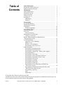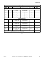
1
Programming
Washer-Extractor
Pocket Hardmount
Variable-Speed
WE-6 Control
Models Starting Serial Code 3120473576
WE-6 Firmware ID Code HRWC18 and greater
or ARWC01 and greater
MC010J
Keep These Instructions for Future Reference.
(If this machine changes ownership, this manual must accompany machine.)
www.comlaundry.com
Part No. F232214R2
December 2005
Table of
Contents
Safety Information..............................................................................
Explanation of Safety Messages...........................................................
Important Safety Instructions ...............................................................
3
3
3
Introduction.........................................................................................
Model Identification .............................................................................
Nameplate Location..............................................................................
Replacement Parts ................................................................................
Customer Service..................................................................................
Introduction...........................................................................................
LED Display ....................................................................................
Simulator..........................................................................................
5
5
5
5
5
7
7
7
Programming ......................................................................................
Keypad Identification ...........................................................................
Entering Program Mode .......................................................................
Setup Mode...........................................................................................
To Enter Setup Mode .......................................................................
Programming Tutorial ..........................................................................
Programming Hints...............................................................................
Test Cycle .............................................................................................
Wet Clean Testing............................................................................
Manual Mode Control Feature..............................................................
Auxiliary Connections .....................................................................
Balance Timing Sequence for Information on
Preprogrammed Cycles ......................................................................
Cycle Programming ..............................................................................
Displaying a Cycle in Memory ........................................................
Editing a Cycle.................................................................................
Erasing a Cycle in Memory .............................................................
Programming a Wet Clean Cycle ....................................................
Step Programming ................................................................................
Programming a Fill without Spray...................................................
Programming a Fill Temperature.....................................................
Programming a Supply Step – Models with 8 Supplies ..................
Programming Heat ...........................................................................
Programming a Wash Step...............................................................
Programming a Wash 5 Thermal Cool-Down .................................
Programming a Wash Drain (Wash 7) Step.....................................
Programming No Reversing ............................................................
Programming a Soak Step................................................................
Programming a Drain Step...............................................................
Programming a Flush Step...............................................................
Programming a Reuse Drain Step with Third Party
Water Reuse System.......................................................................
Programming a Fill through Auxiliary Fill Valve with
Third Party Water Reuse System ...................................................
Programming a Spin Step ................................................................
Spins.................................................................................................
Stop Routine.....................................................................................
9
9
9
10
10
14
17
18
18
18
19
19
20
20
21
22
22
22
22
22
24
27
27
28
29
29
29
30
30
30
31
31
32
32
© Copyright 2005, Alliance Laundry Systems LLC
All rights reserved. No part of the contents of this book may be reproduced or transmitted in any form or by any
means without the expressed written consent of the publisher.
F232214
© Copyright, Alliance Laundry Systems LLC – DO NOT COPY or TRANSMIT
1
Programming a Spray Rinse Step ....................................................
Auxiliary ..........................................................................................
Balance Detection.................................................................................
Balance Switch Detection ................................................................
Simulator Operation and Program Transfer .........................................
Simulator Operation.........................................................................
Transferring All Cycles from Computer to Simulator .....................
Transferring One Cycle from Computer to Simulator .....................
Transferring All Cycles from Simulator to Computer .....................
Transferring One Cycle from Simulator to Computer .....................
Preprogrammed Cycles.........................................................................
Cycle Categories ..............................................................................
Standard Supply Legend ..................................................................
Standard Cycle Charts......................................................................
2
© Copyright, Alliance Laundry Systems LLC – DO NOT COPY or TRANSMIT
32
33
34
35
35
35
37
37
37
38
38
39
39
40
F232214
Safety Information
Explanation of Safety Messages
Precautionary statements (“DANGER,” “WARNING,”
and “CAUTION”), followed by specific instructions,
are found in this manual and on machine decals. These
precautions are intended for the personal safety of the
operator, user, servicer, and those maintaining the
machine.
DANGER
DANGER indicates the presence of a
hazard that will cause severe personal
injury, death, or substantial property
damage if the danger is ignored.
WARNING
WARNING indicates the presence of a
hazard that can cause severe personal
injury, death, or substantial property
damage if the warning is ignored.
CAUTION
CAUTION indicates the presence of a
hazard that will or can cause minor
personal injury or property damage if the
caution is ignored.
Additional precautionary statements (“IMPORTANT”
and “NOTE”) are followed by specific instructions.
IMPORTANT: The word “IMPORTANT” is used
to inform the reader of specific procedures where
minor machine damage will occur if the procedure
is not followed.
NOTE: The word “NOTE” is used to communicate
installation, operation, maintenance or servicing
information that is important but not hazard
related.
Important Safety Instructions
WARNING
To reduce the risk of fire, electric shock,
serious injury or death to persons when
using your washer, follow these basic
precautions:
W023
1. Read all instructions before using the washer.
2. Refer to the GROUNDING INSTRUCTIONS in
the INSTALLATION manual for the proper
grounding of the washer.
3. Do not wash textiles that have been previously
cleaned in, washed in, soaked in, or spotted with
gasoline, kerosene, waxes, cooling oils, drycleaning solvents, or other flammable or
explosive substances as they give off vapors that
could ignite or explode.
4. Do not add gasoline, dry-cleaning solvents, or
other flammable or explosive substances to the
wash water. These substances give off vapors that
could ignite or explode.
5. Under certain conditions, hydrogen gas may be
produced in a hot water system that has not been
used for two weeks or more. HYDROGEN GAS
IS EXPLOSIVE. If the hot water system has not
been used for such a period, before using a
washing machine or combination washer-dryer,
turn on all hot water faucets and let the water
flow from each for several minutes. This will
release any accumulated hydrogen gas. The gas is
flammable, do not smoke or use an open flame
during this time.
6. Do not allow children to play on or in the washer.
Close supervision of children is necessary when
the washer is used near children. This is a safety
rule for all appliances.
7. Before the washer is removed from service or
discarded, remove the door to the washing
compartment.
8. Do not reach into the washer if the wash drum is
moving.
F232214
© Copyright, Alliance Laundry Systems LLC – DO NOT COPY or TRANSMIT
3
Safety Information
9. Do not install or store the washer where it will be
exposed to water and/or weather.
10. Do not tamper with the controls.
11. Do not repair or replace any part of the washer, or
attempt any servicing unless specifically
recommended in the user-maintenance
instructions or in published user-repair
instructions that the user understands and has the
skills to carry out.
12. To reduce the risk of an electric shock or fire, DO
NOT use an extension cord or an adapter to
connect the washer to the electrical power source.
13. Use washer only for its intended purpose,
washing textiles.
14. Never wash machine parts or automotive parts in
the machine. This could result in serious damage
to the basket.
15. ALWAYS disconnect the washer from electrical
supply before attempting any service. Disconnect
the power cord by grasping the plug, not the cord.
16. Install the washer according to the
INSTALLATION INSTRUCTIONS. All
connections for water, drain, electrical power and
grounding must comply with local codes and be
made by licensed personnel when required.
17. To reduce the risk of fire, textiles which have
traces of any flammable substances such as
vegetable oil, cooking oil, machine oil,
flammable chemicals, thinner, etc., or anything
containing wax or chemicals such as in mops and
cleaning cloths, must not be put into the washer.
These flammable substances may cause the
fabric to catch on fire by itself.
18. Do not use fabric softeners or products to
eliminate static unless recommended by the
manufacturer of the fabric softener or product.
20. Replace worn power cords and/or loose plugs.
21. Be sure water connections have a shut-off valve
and that fill hose connections are tight. CLOSE
the shut-off valves at the end of each wash day.
22. Loading door MUST BE CLOSED any time the
washer is to fill, tumble or spin. DO NOT bypass
the loading door switch by permitting the washer
to operate with the loading door open.
23. Always read and follow manufacturer’s
instructions on packages of laundry and cleaning
aids. Heed all warnings or precautions. To reduce
the risk of poisoning or chemical burns, keep
them out of the reach of children at all times
(preferably in a locked cabinet).
24. Always follow the fabric care instructions
supplied by the textile manufacturer.
25. Never operate the washer with any guards and/or
panels removed.
26. DO NOT operate the washer with missing or
broken parts.
27. DO NOT bypass any safety devices.
28. Failure to install, maintain, and/or operate this
washer according to the manufacturer’s
instructions may result in conditions which can
produce bodily injury and/or property damage.
NOTE: The WARNINGS and IMPORTANT
SAFETY INSTRUCTIONS appearing in this
manual are not meant to cover all possible
conditions and situations that may occur. Common
sense, caution and care must be exercised when
installing, maintaining, or operating the washer.
Any problems or conditions not understood should be
reported to the dealer, distributor, service agent or the
manufacturer.
19. Keep washer in good condition. Bumping or
dropping the washer can damage safety features.
If this occurs, have washer checked by a qualified
service person.
4
© Copyright, Alliance Laundry Systems LLC – DO NOT COPY or TRANSMIT
F232214
Introduction
Model Identification
Replacement Parts
Information in this manual is applicable to these
models:
If literature or replacement parts are required, contact
the source from which the washer-extractor was
purchased or contact Alliance Laundry Systems LLC
at (920) 748-3950 for the name of the nearest
authorized parts distributor. A parts manual may be
ordered by returning the reply card provided with each
washer-extractor.
UW35PV
UW100PV
UW60PV
UW125PV
UW80PV
UW150PV
Nameplate Location
Customer Service
The nameplate is located on cagewrap, on side of AC
Inverter Drive Compartment and on Electric Heat
Contractor Box (if equipped). Always provide the
machine’s serial number and model number when
ordering parts or when seeking technical assistance.
Refer to Figure 1.
For technical assistance, contact your local distributor
or call:
MODEL EXAMPLE OF NAMEPLATE LOCATION
3
(920) 748-3121
Ripon, Wisconsin
A record of each washer-extractor is on file with the
manufacturer. Always provide the machine’s serial
number and model number when ordering parts or
when seeking technical assistance. Refer to Figure 2.
1
2
P
U
S
H
PHM618N
1
2
3
Near Supply Valves on Cagewrap
Below Inverter Exhaust Fan on Electric Heat
Box (if equipped)
Side of AC Drive Compartment
Figure 1
F232214
© Copyright, Alliance Laundry Systems LLC – DO NOT COPY or TRANSMIT
5
Introduction
Model Number Familiarization Guide
Sample Model Number: UW60PVXU80001
UW
Model Number Prefix
60
Washer-Extractor Capacity (pounds dry weight of laundry)
P
Type of Electrical Control
P = WE-6 Control
V
Washer-Extractor Speed Capabilities
V = 7 Speeds
X
Electrical Characteristics
U8
0001
Design Series
J = Jog Feature (UW150 Models Only)
Option Identification (varies from machine to machine)
UW60PVXU80001
00000000000
200 – 240
20
50 – 60
2/3
60
N/A
14
1/3
27
N/A
813
0.0
Drawings:
ETL Listed
Conforms To ANSI/UL Std. 1206, 3rd Ed
Certified To CAN/CSA Std. C22.2 No.53-1968
EXAMPLE OF NAMEPLATE
PHM533R
PHM533R
Figure 2
6
© Copyright, Alliance Laundry Systems LLC – DO NOT COPY or TRANSMIT
F232214
Introduction
Introduction
LED Display
The WE-6 control is a field-programmable solid-state
control capable of storing and running up to
39 preprogrammed ready-to-use cycles. A detailed
description of these cycles can be found in the
Standard Cycle Charts section.
The WE-6 control has a six-digit LED display.
References to display indications pertain to the first
four digits of the display reading left to right. The last
two digits on the right side of the display will indicate
either the last cycle used or the current cycle in
progress. Refer to Figure 3.
Never turn the power off while the control mode
switch is in the PROGRAM position. Programmed
data and cycle information will be lost and need
reprogramming. Always return the mode switch to
RUN position before turning the power off.
2
3
1
Never leave the mode switch key inserted in the switch
lock where it may be accessible to unauthorized
personnel not familiar with programming procedures.
The control in this washer-extractor is continuously on
the alert for problems within the machine. When the
control detects a problem, it immediately flashes a
letter or number or both on the display. It may activate
the signal buzzer as well.
MC007A
1
2
3
Function Being Executed
Step Number
Cycle Number
Figure 3
Table 2 lists the various displays and what they mean.
Simulator
A simulator, available at extra cost, is an optional
accessory that allows the user to preprogram cycles for
all WE-6 control washer-extractors in a facility. The
information is preprogrammed into the simulator, the
simulator is connected to the washer-extractor needing
updates and the preprogrammed information is
downloaded into the WE-6 control on the washerextractor.
F232214
© Copyright, Alliance Laundry Systems LLC – DO NOT COPY or TRANSMIT
7
Notes
8
© Copyright, Alliance Laundry Systems LLC – DO NOT COPY or TRANSMIT
F232214
Programming
Keypad Identification
Entering Program Mode
NOTE: Machines are factory programmed with
basic cycles to make the units operational without
programming at installation.
1. Locate key-operated programming switch on left
side of control module, viewed from front.
2. Insert key and turn switch to PROGRAM
position.
3. Display will read “CY00.”
MC010J
Figure 4
All sixteen keypads are used in Program Mode.
Specific functions are printed in red on keypads.
Keypad 1–6 and Auxiliary/No Reverse keypad are
dual function keypads in Program Mode. In each
instance (with exception of Warm/High keypad), when
a keypad is first pressed in a programming step, the
word printed at top of keypad applies. In most
instances, the next time same keypad is pressed or if
another keypad has already been pressed in
programming a step, the word printed on bottom of
keypad applies.
F232214
© Copyright, Alliance Laundry Systems LLC – DO NOT COPY or TRANSMIT
9
Programming
Setup Mode
NOTE: Enter Setup Mode while in Program Mode.
Refer to Entering Program Mode section.
In Setup Mode, prompting the WE-6 allows the
following options:
• Displaying sump temperature in Centigrade or
Fahrenheit (FAr or CEN).
• Recognizing and controlling one or two
independent drains. (Two independent drains will
apply only for special applications.)
• Enabling or disabling Advance keypad in Run
Mode.
• Enabling or disabling Manual Mode.
• Enabling or disabling wet clean functions (affects
Auxiliary 1 and 2 outputs).
• Selecting balancing routine (active if inverter
balance detection is utilized). Long balance
(L BAL) or short balance (S BAL) routine timing.
• Selecting machine model.
• Reading or resetting cycle count.
NOTE: Machine comes from manufacturer with
WE-6 control set up for use with machine in which
it is installed. If control needs to be reset, refer to To
Enter Setup Mode.
IMPORTANT: WE-6 control must be configured
for washer-extractor in which it is installed. Failure
to set up control for proper machine may cause
control to malfunction and void warranty.
IMPORTANT: Once WE-6 control has been
through model Setup Mode one time, it will store
machine model configuration information in
control memory and never display “SETUP” again.
It is very important that WE-6 control PC board,
or the socketed chips in this PC board are NEVER
removed from one washer and installed in another
washer without first updating and verifying model
configuration as described in instruction. Warranty
will be void if not set up properly.
IMPORTANT: DO NOT install an earlier version
WE-6 control board. THIS WILL CREATE
HAZARDOUS CONDITIONS FOR OPERATOR
AND VOID WARRANTY. Contact Alliance
Laundry Systems for additional details and
information regarding free replacement of old
control boards.
10
IMPORTANT: WE-6 door lock circuit MUST NOT
allow entry into door until basket has come to a
complete stop.
To Enter Setup Mode
1. Enter Program Mode. Refer to Entering
Program Mode section.
2. Press Auxiliary keypad, 2 keypad, and 9 keypad
in that order. Display shows either “CEN” (for
degrees shown in Centigrade) or “FAr” (for
degrees shown in Fahrenheit). Press 0 keypad to
change selection.
3. Press Enter keypad.
4. Display shows either “1DRAIN” or “2DRAIN.”
The normal prompt for most applications is
“1DRAIN.” “2DRAIN” is used only for special
applications. Consult manufacturer for full
details. To choose alternate feature, press 0
keypad.
NOTE: Enabling second drain via Auxiliary 2
output precludes control of recirculation pump and
is not necessary for Premium Wet Clean Module.
5. Press Enter keypad.
6. Display shows “ADV” or “NO ADV.” The
prompt “NO ADV” will disable Advance keypad
in Run Mode, thereby preventing operator from
advancing control through steps of cycle before
completion. In addition, it will not be possible to
advance to any step before starting a cycle if “NO
ADV” is selected. Press 0 keypad to select enable
or disabling the Advance feature.
7. Press Enter keypad
8. Display will read either “MANUAL” or “NO
MAN.” If “MANUAL” is displayed, Manual
Mode will be enabled during normal operation. If
“NO MAN” is displayed, Manual Mode will be
disabled when a cycle is run, even if Manual
operation keypad sequence is entered. To select
enabling or disabling the manual mode feature,
press 0 keypad.
9. Press Enter keypad. When desired Manual Mode
option is displayed, display will read “WET CL”
or “NO WCL.” If “WET CL” is displayed, wet
clean functions are enabled. If “NO WCL” is
displayed, press 0 keypad to enable or disable
Wet Clean feature.
© Copyright, Alliance Laundry Systems LLC – DO NOT COPY or TRANSMIT
F232214
Programming
10. Press Enter keypad. When desired Wet Clean
option is displayed, display will read “S BAL”
(short balance timing sequence) or “L BAL”
(long balance timing sequence). Refer to Table 1
for appropriate sequence. Press 0 keypad to
change selection.
11. Press Enter keypad.
Model
Display
UW60PVT
L BAL
Design 5 models greater than 60 lbs.
L BAL
Design 6 models and greater, 60 lbs.
and less
S BAL
Design 6 models and greater 60 lbs.
and over
L BAL
Table 1
12. Press Enter keypad. Display will read “UW35,”
“UW60,” “UW80,” “UW100,” “UW125” or
“UW150.” Press 0 keypad until display reads
correct model. Model selection must be correct to
ensure proper machine function.
13. Press Enter keypad when desired balance times
sequence is displayed. Display will read
“USEDxx.” (The “xx” means number of cycles
run.)
The count can be left as it reads on display, or it
can be reset to “00.”
• To leave count unaltered, press Enter keypad
to return to normal programming mode.
• To reset count, press 0 keypad. Display will
read “USED00.”
Press Enter keypad to return to normal
programming mode.
Control stores cycle count in its memory. If
power to control is interrupted, count will
automatically be set at “00.”
If a daily count is desired, display should be read
at end of day and then reset prior to running next
day’s first cycle. (Display resets automatically
after cycle count reaches 99.)
14. Return Program Mode switch to RUN position
and remove key. Prompting is complete.
NOTE: Prompting will change parameters in all
cycles programmed.
F232214
© Copyright, Alliance Laundry Systems LLC – DO NOT COPY or TRANSMIT
11
Programming
Programming Keypad
Keypad
1
2
3
Erase Cycle
Red
Keypads
Cold
Low
Cold is pressed when step requires cold water.
Low is pressed for low-level fill.
Hot
Med./Fill
Hot is pressed when step requires hot water.
Med./Fill is pressed to select medium water level.
Fill is pressed in Manual Mode to operate fill valves.
Warm
High
Warm is pressed when step requires warm water.
High is pressed for high-level fill.
Erase Cycle
Erase Cycle and a two-digit cycle code number are pressed to erase a cycle from
memory.
Wash
Wash is pressed when step is a wash or dilution rinse. Then keypad 1, 2, 3, 4, 5, or 6 is
pressed to choose type of agitation. Press keypad 7 after Wash keypad (in Program Mode
when creating a new step) to create a Wash Drain Step. Refer to Programming a Wash
Step and Programming a Drain Step sections for additional details.
Flush is pressed to keep drain open when water is added to machine. A temperature
selection keypad (Hot, Cold, Warm) must be pressed before Flush keypad. When Flush
is programmed, water is added through door spray nozzle only; basket rotates in low
speed forward only.
Flush
4
Heat
5
Heat is pressed when auxiliary heat is needed. This must be followed by a specific
temperature selection, such as 165°F. Temperature must be entered; then a time assigned
to reach that temperature must be entered.
Rinse is pressed when a spin-spray rinse (not available on UW125 models) is desired.
Before Rinse keypad is pressed, a temperature keypad must be pressed: Hot, Cold, or
Warm. Drain will remain open, and basket will rotate at medium-spin speed (high speed
on two-speed only machines). Water is added through door spray nozzle only.
Rinse
Supply
6
Add Cycle
Description
Supply is pressed when soap, bleach, or other chemicals are desired. Keypad 1, 2, 3, 4, or
5 must be pressed to indicate specific supply dispenser being used. Combinations of these
supplies can be programmed. Refer to Programming a Supply Step.
Over is pressed when an overflow of water is desired. Drain is closed and water is added,
using fill valves only, without regard to level. Water flows out overflow connection for
time assigned to step.
Over
Add Cycle
Add Cycle is pressed to begin process of programming a new cycle into memory.
Table 2
12
© Copyright, Alliance Laundry Systems LLC – DO NOT COPY or TRANSMIT
F232214
Programming
Table 2 (Continued)
Programming Keypad (Continued)
Keypad
Red
Keypads
Description
Soak
Soak is used when no agitation is desired. This follows a fill and/or supply step. Time
must be assigned in hours and minutes. (Wash 3 also provides no agitation.)
Medium
Speed
Medium Speed is pressed when a medium spin only is desired for washing delicate items
not suited for high speed spin or when an intermediate spin is desired.
High Speed
High Speed is pressed when a fast spin is desired. Pressing High Speed keypad once will
activate the H1 spin; twice, the H2 spin; and three times, H3 spin.
Edit Cycle
Edit Cycle
Add Step
Add Step
Edit Cycle is pressed followed by a two-digit cycle code number to display steps of a
preprogrammed cycle. Cycle may be altered during edit cycle procedure by deleting,
changing, or adding steps.
Add Step is pressed to add a step to an existing cycle during edit cycle procedure.
Clear (black
on red
background)
Clear (black
on red
background)
Clear is pressed when an error has been made in programming a step. Instead of pressing
Enter as step is completed, press Clear to eliminate incorrect information. (Clear should
never be pressed when displaying a cycle unless a particular step is to be eliminated or
changed. Refer to Displaying a Cycle in Memory.)
Drain
Drain is pressed after a wash, dilution rinse, or soak step is programmed in order to
remove water from machine. A time must be assigned that will allow machine to reach
empty. If control has been prompted for two independent drains, press 1 keypad or 2
keypad for desired drain valve. Refer to Set Up Mode section in Operation Manual.
There are always four possible selections for drain step. For special applications utilizing
“2DRAIN,” contact manufacturer. These are selected after Drain keypad is pressed. Press
1 keypad for drain 1 (main drain), 2 keypad for a drain to reuse tank A, and 3 keypad for
a drain to reuse tank B or 5 keypad for a drain to sewer. Drain 5 is identical to drain 1
step, without load rebalancing during drain step (this minimizes drain time). The option
for reducing drain time is only available for Drain 5. All other drains require the full
amount of time. Programming a medium spin speed, or spray rinse after a Drain 5 Step is
recommended. If Drain 5 is programmed before an H3 spin, control will default to speed
below maximum spin speed. Program a Wash 7 step for potentially the shortest drain
step. Refer to Programming a Wash Step.
Auxiliary
Auxiliary
No Reverse
No Reverse
Auxiliary is pressed to activate buzzer or other auxiliary output. NOTE: Auxiliary 4 is
used to activate recovery fill valve for machines equipped with water reuse system.
No Reverse is used to rotate basket in one direction only during a wash step and should
be pressed just before pressing Enter keypad.
Enter
Enter
7
8
9
0
F232214
Enter is pressed to enter programming information into control’s memory.
© Copyright, Alliance Laundry Systems LLC – DO NOT COPY or TRANSMIT
13
Programming
Programming Tutorial
The following procedure guides the programmer
through a complete cycle and allows hands-on
experience for programming cycles. The complete
cycle is listed at the end of this section.
7. For this tutorial, step 2 in cycle will be an
addition of a supply step.
a. To add supply No. 1, press Supply keypad (6)
and then 1 keypad. Display will read
“S10201.”
1. Enter Program Mode. Refer to Entering
Program Mode section.
b. Press Enter keypad and display will read
“M---S.”
2. Press Add Cycle keypad. Display will read
“ACYC00.”
c. Enter desired time in minutes and seconds for
supply valve to be turned on (thirty seconds is
the recommended time).
3. A two-digit number from 01 to 39 must be
entered. Refer to Standard Cycle Charts section.
NOTE: Cycle number 01 is recommended because
standard program versions use this short cycle for
performing a chemical supply setup.
4. If using cycle number 01, press 0 keypad, then
1 keypad, then Enter keypad. Display will read
“CYC01.”
a. If display alternately flashes “EXISTS” and
“EDIT?,” press Clear/Stop keypad. Display
will read “CYC01.”
b. Erase existing cycle by pressing Erase Cycle
keypad. Display will read “ECYC01.” Press
0 keypad, then 1 keypad, then Enter keypad.
Display will read “WAIT” briefly and then
“CYC01.”
c. Press Add Cycle keypad. Display will read
“ACYC01.” Press 0 keypad, then 1 keypad,
then Enter keypad. Display will show “0101.”
(“01” means step 1 and “01” means cycle
number.)
5. Enter desired water temperature and fill level. For
this tutorial, step 1 will be Hot Fill and Low
Level.
a. Press Hot keypad (2) and then Low keypad
(1). Display will read “HL0101.”
Press 0 keypad for minutes, and display will
read “0M-00S.”
Press 3 keypad and then 0 keypad. Display
will read “0M-30S,” indicating a supply time
of thirty seconds.
8. Press Enter keypad. Display will change to read
“0301,” indicating control is ready for step 3 of
cycle 01.
9. If no other supply is required, the next step is to
choose type of wash desired and assign it a time.
Refer to Programming a Wash Step section for
available wash types. For this tutorial choose a
wash with standard reversing action (Wash 1) and
a time of six minutes.
a. Press Wash keypad (4) and then 1 keypad.
Display will read “W10301.”
b. Press Enter keypad. Display will read
“M---S.”
c. Enter desired wash time (6 minutes is
recommended). Press 6 keypad. Display will
read “6M-00S,” indicating a wash step of six
minutes.
10. Press Enter keypad. Display will read “0401,”
indicating that control is ready for step 4 of
cycle 01.
b. Press Enter keypad. Display will read
“M---S.”
c. Enter desired fill time. (4 minutes is
recommended.) Press 4 keypad. Display will
read “4M-00S.” (“4M” means 4 minutes and
“00S” means 0 seconds.)
6. Press Enter keypad. Display will read “0201,”
indicating that control is ready for step 2 of
cycle 01.
14
© Copyright, Alliance Laundry Systems LLC – DO NOT COPY or TRANSMIT
F232214
Programming
11. For this tutorial, step 4 will be a drain step.
a. Press Drain keypad (0). (A drain step usually
follows a wash step). Display will read
“D-0401.”
This program allows a choice among drains 1,
a, b or 5 (“5” uses sewer drain). (NOTE: 1 is
sewer, “a” is Tank a and “b” is Tank b.) For
this application, press 5 keypad. Display will
read “D50401.”
NOTE: Drain 5 is identical to Drain 1 without the
rebalancing attempts. Program Drain 5 to shorten
cycle time. Programming a medium spin speed or a
spray rinse step after a Drain 5 step is
recommended. Do NOT program a Drain 5 step if
an H1 spin step or higher is the next step.
b. Press Enter keypad. Display will read
“M---S.”
c. Enter maximum time desired for control to
allow machine to drain to empty. (One minute
is recommended.) Press 1 keypad. Display
will change to “1M-00S,” indicating a drain
step of one minute.
NOTE: The manufacturer does not recommend
more than one minute for a drain step. If machine
does not drain in amount of time programmed,
“EMTY” alarm will be displayed. Refer to Error
Recovery Routine in Operation Manual.
12. Press Enter keypad. Display will now read
“0501,” indicating that control is ready for step 5
of cycle 01.
13. For this tutorial, step 5 in cycles will be a warm
rinse.
a. Press Warm keypad (3) and then Rinse keypad
(5). Display will read “WR0501.”
b. Press Enter keypad. Display will read
“M---S.”
c. Enter rinse time in minutes and seconds. A
spray rinse lasting 2-1/2 minutes is
recommended.
15. For this tutorial, step 6 in cycle will be a warm
fill and high level for a dilution rinse.
NOTE: Rinse key controls a spin-spray rinse. A
dilution rinse is the same as a wash step without the
addition of detergents. Refer to Programming a
Wash Step section.
a. Press Warm keypad (3) twice to turn on two
hot and two cold water valves to reduce fill
time. Display will read “W-0601.” Press High
keypad (3 keypad). Display will read
“WH0601.”
b. Press Enter keypad. Display will read
“M---S.”
c. Enter desired time for control to allow
machine to fill to high level (five minutes is
recommended). Press 5 keypad. Display will
read “5M-00S” indicating a dilution rinse of
5 minutes.
NOTE: If machine does not fill high level in amount
of time programmed, “FILL” alarm will be
displayed. Refer to Error Recovery Routine in
Operation Manual.
16. Press Enter keypad. Display will read “0701.”
17. For this tutorial, step 7 in cycle will be an add
sour.
a. Press Supply keypad (6) and 3 keypad (3 is
for supply 3 location). Display will read
“S30701.”
b. Press Enter keypad. Display will read
“M---S.”
c. Enter length of time for supply to be activated
(thirty seconds is recommended).
Press 0 keypad for minutes; press 3 keypad
and then 0 keypad for seconds. Display will
read “0M-30S” indicating an add sour step of
0 minutes and 30 seconds.
18. Press Enter keypad. Display will read “0801,”
indicating that control is ready for step 8.
Press 2 keypad. Display will read “2M-00S.”
Press 3 keypad and 0 keypad. Display will
read “2M-30S,” indicating a spray rinse of
2 minutes and 30 seconds.
14. Press Enter keypad. Display will read “0601,”
indicating that control is ready for step 6 of
cycle 01.
F232214
© Copyright, Alliance Laundry Systems LLC – DO NOT COPY or TRANSMIT
15
Programming
19. For this tutorial, step 8 will be an agitation action
for dilution rinse.
a. Press Wash keypad (4) and 1 keypad to
program an action with normal reversing.
Refer to Programming a Wash Step section.
Display will read “W10801.”
b. Press Enter keypad. Display will read “M---S.”
c. Enter time for dilution rinse (three minutes is
recommended).
Press 3 keypad. Display will read “3M-00S,”
indicating an agitation action dilution rinse of
3 minutes.
20. Press Enter keypad. Display will read “0901,”
indicating that control is ready for step 9.
21. For this tutorial, step 9 in cycle 9 will be a
dilution rinse water drain.
a. Press Drain keypad. Display will read
“D-0901.” Press 1 keypad for draining to
sewer. Display will read “D10901.”
b. Press Enter keypad. Display will read “M---S.”
c. Enter length of time control will allow
machine to drain (one minute is
recommended).
Press 1 keypad. Display reads “1M-00S,”
indicating a drain step of one minute.
NOTE: Programming a Drain 5 step is identical to
Drain 1, but with a reduced time because there are
no rebalancing attempts. To program Drain 5,
press 5 keypad after Drain keypad. “D50901” will
display. Do not program an H3 spin after Drain 5.
Control will default to a less than maximum spin
speed during H3 (Drain 5 does not attempt to
rebalance the load). It is recommended to program
a medium speed spin or spray rinses after Drain 5.
22. Press Enter keypad. Display will read “1001,”
indicating that control is ready for step 10 of
cycle 01.
23. For this tutorial, step 10 in cycle will be an
extract step.
c. Enter length of time for medium-speed spin
(one minute is recommended).
Press 1 keypad. Display will read “1M-00S,”
indicating 1 minute and 0 seconds.
24. Press Enter keypad. Display flashes “SDLY”
(slow-down delay) for one second.
Display will read “0M-00S,” allowing
programmer to enter time for a slow-down delay.
NOTE: Do not program a slow-down delay time if
the slow-down delay is followed by a spin (all
consecutive spins are skipped when a slow-down
delay is programmed).
For no slow-down delay, press Enter keypad.
25. For this tutorial, step 11 in cycle will be a spin
step.
a. Press High Speed keypad (9) once. Display
will read “H11101.”
NOTE: Pressing High Speed keypad repeatedly
when programming a high speed step will cause
control display to proceed from “H1” to “H2,” and
then to “H3,” maximum-speed spin. After “H3”
appears and High Speed keypad is pressed again,
“H1” will reappear.
b. Press Enter keypad. Display will read
“M---S.”
c. Enter a length of time for high speed spin (six
minutes is recommended). Press 6 keypad.
Display will read “6M-00S.”
NOTE: High Speed spin is not preceded
automatically by medium-speed spin as with
nonvariable-speed UW rigid-mount models.
Medium-speed spin only or high speed spin 1, 2, or
3 may be programmed.
26. Press Enter keypad. Display will flash “SDLY”
(slow-down delay) for one second. (“SDLY” also
displays during the entire actual delay time.)
Display will read “0M-00S,” prompting
programmer to enter a time for slow-down delay.
Display will read “1201.”
a. Press Medium Speed keypad (8). Display will
read “MS1001,” indicating a medium-speed
spin.
b. Press Enter keypad. Display will read
“M---S.”
16
© Copyright, Alliance Laundry Systems LLC – DO NOT COPY or TRANSMIT
F232214
Programming
NOTE: For machines with a WE-6 Firmware
ID Code of HRWC10 or earlier, a slow-down delay
of 60 seconds minimum must be programmed after
each medium-speed, spray-rinse or high speed 1 or
a delay of 99 seconds must be programmed after
each high speed spin 2 or high speed 3.
For machines with software code HRWC18 or
later, no slow-down is required.
NOTE: For machines with a WE-6 Firmware
ID Code of HRWC12 or later, if application
requires that water fill valves remain off while
basket is coasting to a stop, enter desired delay time
(Example: 60 seconds). Press Enter keypad. The
last spin should have no spin delay (“0M-00S”).
27. The previous step ends tutorial. Cycle 01,
consisting of 11 steps, has been programmed.
To end cycle, turn Program Mode switch located
on left side of control module to RUN position
and remove key. Display will read “NEXT.”
Programmer can select Cycle 01 and press Enter
keypad to run cycle as it is set up; or a cycle of
the programmer’s own design can be programmed.
NOTE: Cycle 01 can be reprogrammed as machine
came from factory. Refer to Standard Cycle Charts
section or it can remain as set up in tutorial.
Tutorial Cycle
Step
Description
Min:sec
1
Hot Fill to Low Level
4:00
2
Supply 1
0:30
3
Wash 1
6:00
4
Drain 5
1:00
5
Warm Spray Rinse
2:30
6
Warm/Warm Fill to High Level
5:00
7
Supply 3
0:30
8
Wash 1
3:00
9
Drain 1
1:00
10
Medium Speed Spin
1:00
11
High Speed Spin No. 1
SDLY
Stop Routine
6:00
0:00
Programming Hints
Refer to Standard Cycle Charts section.
NOTE: The control can only be programmed step
by step.
When entering timed portion of a step (such as a fill),
use a time that is reasonable for local installation. If
water pressure is low or if water lines are small,
increase time allowed. Drain lines must be sized
correctly to empty the machine in less than one
minute.
NOTE: Drain times of more than one minute are
not recommended.
Except for soak, heat, and cool-down (Wash 5) steps,
which are timed in hours and minutes, the maximum
time per step is 9 minutes and 99 seconds. If more time
is needed, add more steps to total complete time
desired. For example, if a 15-minute wash is desired,
program a wash step for 9 minutes and 00 seconds,
immediately followed by another wash step for
6 minutes and 00 seconds.
When a fill or addition of supplies without agitation is
desired, first program a Wash 3 step for 0 minutes and
01 seconds. Program fill or supply step as desired.
When control advances to next step, it will remain in
Wash Mode as programmed in previous step unless
instructed to do otherwise.
Program a wash drain before a fill step. A wash drain
has no rotation, has the sewer (main) drain open and
does not attempt to rebalance the load, if followed by a
fill. Refer to Programming a Wash Step section and
Programming a Drain Step section for additional
details.
Table 3
F232214
© Copyright, Alliance Laundry Systems LLC – DO NOT COPY or TRANSMIT
17
Programming
Test Cycle
Manual Mode Control Feature
Cycle number 39 is a test cycle used to analyze
washer-extractor functions.
Manual control is available only while a
preprogrammed cycle is in progress, and if Manual
Mode is prompted in the WE-6 programming. With
the exception of motor speeds, the reuse tank B drain
and tank A and B fill valves, and the door unlock
output, the WE-6 computer outputs can be operated
manually from the keypad. (In order to ensure proper
sequencing, all motor speeds are always controlled by
the computer.)
Step 01 in cycle number 39 is a cold fill to low level.
This step is designed to give not quite enough time to
complete a fill, causing the display to read “FILL.”
Press the Start keypad to continue the fill, and the test
cycle will proceed.
Step 02 in the test cycle is a drain step. Again, the time
allotted is shorter than it would be in a normal cycle.
The display will read “EMTY.” To proceed, press the
Start keypad.
The steps in the test cycle are relatively short with the
exception of steps 3, 21, 25, 27, 28, and 29. These can
be shortened by pressing the Advance keypad to go on
to the next step.
The operator may skip to any next step in the cycle
with the exception of a drain step: Drain steps must be
allowed to complete. To skip forward in the test cycle,
press the Advance keypad.
NOTE: The Advance feature may be disabled.
Wet Clean Testing
Wet clean processing outputs are tested through the
energizing of the Auxiliary 1 output in step 18 and
Auxiliary 2 output in step 19. Steps 30 through 41 are
designed to test water reuse processing, if this option
is installed. If it is not, the outputs associated with
each step will be energized, and the cycle will
conclude normally.
NOTE: Prompts for “1DRAIN” and “WET CL”
must be selected when prompting the WE-6
microcomputer in order for steps 18 and 19 to
work properly for wet clean processing.
NOTE: When the Manual Mode control feature is
activated, the operator must supply on/off
commands for the controllable outputs. If an
output is on, it will remain on until turned off by
the operator or until the assigned time for the
Manual Mode expires. This can be as long as 9
minutes and 99 seconds.
In normal operation, when the Program Mode switch
is in the RUN position, only the operations printed in
black on the keys are accessible to the operator.
During the Manual Mode, normal cycle timing is
suspended. When the Manual Mode is entered, the
operations printed in red on the keys and mentioned in
the following discussion are activated.
Entering the Manual Mode during a fill operation is
not recommended. This bypasses the water-level
switch inputs, and the water must be turned off
manually by the operator.
The following procedure must be accomplished within
three seconds in order to enter the Manual Mode:
1. Press the Manual key.
2. Then press three number keys to assign a time in
minutes and seconds to the Manual Mode. For
example, press key 2, key 3, and key 0 to enter
the Manual Mode for 2 minutes and 30 seconds.
3. Then press the Add Step key.
18
© Copyright, Alliance Laundry Systems LLC – DO NOT COPY or TRANSMIT
F232214
Programming
When the computer receives all these inputs within the
three-second time limit, it will enter the Manual Mode
for the time assigned. The computer display will flash
between “MAN230” (reflecting the time chosen in
step 2 of the above procedure) and the current cycle
step display for four seconds.
NOTE: If “NO MAN” is prompted and the normal
key sequence for Manual Mode is entered, the
computer will display only the remaining cycle
time.
After four seconds, the display will flash between
“MANUAL” and the current cycle step display for the
remainder of the assigned time.
Manual Mode operation will automatically end when
the assigned time elapses. Normal program timing will
then resume from the same point in the cycle where
the Manual Mode was entered. To exit the Manual
Mode and return to normal program timing before the
assigned time elapses, press the Start key.
All water fill and spray rinse valves, supplies, heat (if
the washer-extractor has reached low water level), and
auxiliary outputs can be manually controlled. The heat
output requires that only the Heat key be pressed. All
other outputs require that two keys be pressed. For
example, to turn on the cold fill valve, press the keys
Cold and Fill. When an output is on, pressing the same
key or keys which caused it to energize will turn it off.
Thus, to turn off the cold fill valve, press the keys Cold
and Fill once again.
Auxiliary Connections
The Auxiliary Fill Valve is set up to be connected to a
third party reuse water supply only.
CAUTION
Never connect the Auxiliary Fill Valve to
a potable water supply.
W508
This valve is mounted on the right side of the machine
and is equipped with a hose barb on the inlet side. The
auxiliary drain line has a normally closed drain valve
and exits the left rear of the machine.
Balance Timing Sequence for
Information on Preprogrammed
Cycles
Inverter drive balance timing sequence, if active, will
occur during a drain step. This prevents machine from
reaching a high speed when a poorly balanced load is
sensed. Short timing sequence (“S BAL”) and long
timing sequence (“L BAL”) are as follows:
1. Control enters drain step (displays “D1,” “Da,” or
“Db”) with drain(s) initially closed. The first
phase of drain step takes less than 10 seconds
(control verifies balance system type and
performs a short sequence to reset any possible
drive conditions that can be reset).
2. Machine runs at regular wash speed forward (not
1/2 wash speed) for a total of 10 seconds if “S
BAL” or for a total of 15 seconds if “L BAL.”
3. Machine runs at distribution speed for a total of
15 seconds if “S BAL” or for 20 seconds if “L
BAL.”
4. Drain(s) open.
5. Control waits for empty condition.
6. After empty condition appears, control waits for
20 seconds before checking the balance signal if
“S BAL” or 30 seconds if “L BAL.” Drain 5 stays
in this step for 2 seconds and ignores out-ofbalance conditions. Drain 5 MUST be followed
by a medium spin speed or spray rinse.
7. Control then monitors balance signal from
inverter drive for up to 5 seconds. If balance is
okay, control proceeds to next step after drain
when 5-second time expires. If balance is not
okay at any point during this 5 seconds, control
will return to regular wash speed for 10 seconds
if “S BAL” or for 15 seconds if “L BAL.”
Control will repeat timing sequence, beginning
with step 3 above, in an attempt to balance load.
For models with Firmware ID Code ARWC01 and
greater, the inverter drive uses a special signaling
sequence that will limit the maximum spin speed
based on the load balance. If the spin speed is
decreased from the programmed spin speed from
being out-of-balance, display flashes the reduced spin
speed and the programmed spin speed.
The following are possible spin speeds:
MS – speed limited to medium speed
H1 – speed limited to H1 spin speed
H2 – speed limited to H2 spin speed
H3 – speed limited to step below maximum spin speed
F232214
© Copyright, Alliance Laundry Systems LLC – DO NOT COPY or TRANSMIT
19
Programming
NOTE: Any time machine goes from wash speed to
spin speed, a drain step must be programmed prior
to high speed step to allow load balancing. Any spin
speed steps for which a drain step has not occurred
will be skipped.
NOTE: For steps Drain 1, a, b or 5 ONLY, control
will not advance through a drain step due to
balance procedure. Control will neither start in a
spin step nor allow any spin step(s) for which
proper balancing has not occurred.
Cycle Programming
Displaying a Cycle in Memory
1. Enter Program Mode. Refer to Entering
Program Mode section.
2. Press the Edit Cycle keypad on the keypad. The
display will read “DCYC00.”
3. Press the two-digit code to display the desired
cycle number: For example, press 2 keypad and
then 5 keypad to select cycle 25. The display will
read “DCYC25.”
4. Press Enter keypad. The control will search for
cycle information for this cycle number.
5. If cycle information does exist for cycle 25,
control will display “0425,” for example, to
indicate that cycle 25 has been run four times. To
clear count (reset it to zero), press 0 keypad.
Display will then show “0025.”
If clearing the count is not necessary or if it has
just been cleared, press Enter keypad. Control
will display “TH0125,” indicating first step of
cycle 25.
6. Press Advance keypad to move to next step of the
cycle. To access further information pertaining to
each step (for example, temperature and/or time),
press Enter keypad. If display shows a
temperature, press Enter keypad again to display
time. Press Enter keypad once more to advance to
next step.
7. At cycle end, control will display “END-25” for
two seconds and return to normal programming
mode.
8. Return Program Mode switch to RUN position
and remove key.
NOTE: Never press Clear keypad while displaying
a cycle in memory except to edit or delete a step.
If no cycle information exists, the control will
flash “NCYC25” followed by “ADD?” To add
this cycle, press Enter keypad and proceed to add
the desired steps for this cycle. Refer to Step
Programming section for specific programming
instructions. If adding this cycle is not desired,
press the Clear keypad, and control will then
return to the normal programming mode.
20
© Copyright, Alliance Laundry Systems LLC – DO NOT COPY or TRANSMIT
F232214
Programming
Editing a Cycle
To edit a cycle in memory or to change, add, or delete
a step:
1. Enter Program Mode. Refer to Entering
Program Mode section.
2. Press Edit Cycle keypad. Display will read
“DCYC00.”
3. Press two-digit code for cycle requiring editing:
For example, press 2 keypad and then 5 keypad to
select cycle 25.
4. Press Enter keypad. Control will search for cycle
information for this cycle.
If no cycle information exists, control will flash
“NCYC25” followed by “ADD?” To add this
cycle, press Enter keypad and proceed to add the
desired steps for this cycle. Refer to Step
Programming section for specific programming
instructions. If adding this cycle is not desired,
press Clear keypad. Control will then return to
normal programming mode.
5. If cycle information does exist for cycle 25,
control will display “0425,” for example, to
indicate that cycle 25 has been run four times. To
clear count (reset it to zero), press 0 keypad.
Display will read “0025.”
If clearing count is not necessary or if it has just
been cleared, press Enter keypad. Control will
display “HH0125,” indicating first step of
cycle 25.
6. Press Advance keypad to move to next step of
cycle.
7. Press 0 keypad to back up to previous step.
8. To access further information about each step
(for example, temperature and/or time), press
Enter keypad.
If display shows a temperature, press Enter
keypad again to display time.
10. To change a step within cycle, press Clear keypad
once while control is displaying step to be edited.
Enter new step, using same procedure for adding
a step to a new cycle. Refer to Step
Programming.
NOTE: If, after Clear keypad is pressed, it is
decided that clearing step is not desired, press Edit
Cycle keypad to restore step. (This will work only if
a step identification was displayed before pressing
Clear keypad. At other points in the step–such as a
time or temperature display–this restoration effort
will not work.)
11. To change time assigned to a step, press Clear
keypad once while control is displaying
unwanted time.
12. To add a step within cycle, press Add Step
keypad. The step will be added into the cycle
after the step presently displayed.
Control will check to see if enough cycle
memory is left in the cycle to add a step. (Each
cycle may contain up to 51 steps.)
If cycle memory for this cycle is full, control will
display “CYFULL” for two seconds and return to
displaying the previous step. If control can add a
step, the new step number will be displayed and
the step may be added (as when adding a step to a
new cycle). Refer to Step Programming section.
13. To delete a step within a cycle, press Clear
keypad while control is displaying the step to be
deleted. Press Clear keypad again: display will
read “WAIT” while it is deleting the step.
Control will display the next step in the cycle,
using the same step number as the deleted step.
NOTE: If Add Cycle keypad is pressed by mistake
instead of Edit Cycle keypad when the cycle
number to be edited is entered, display will flash
“EXISTS” and “EDIT?” To recover, press Enter
keypad, and control will change to Edit Mode.
9. Press Enter keypad once more to advance to next
step.
NOTE: At any time, programmer can put the
Program Mode switch in RUN position, and control
will return to normal running mode, provided all
data for last step edited is entered.
F232214
© Copyright, Alliance Laundry Systems LLC – DO NOT COPY or TRANSMIT
21
Programming
Erasing a Cycle in Memory
Step Programming
IMPORTANT: Erasing a cycle in memory is not
reversible.
Programming a Fill without Spray
1. Enter Program Mode. Refer to Entering
Program Mode section.
2. Press Erase Cycle keypad. Display will read
“ECYC00.”
3. Press two-digit code for cycle number to be
erased. Display will read “ECYC25” if cycle 25
is selected.
This process is used in temperature-controlled fill
steps. Water is added through the sump only.
To program a fill without spray, program a cold, hot, or
warm fill to level as in a normal fill step; however,
instead of pressing Enter keypad after selecting level,
press Auxiliary keypad. Control will display a lower
case “c,” “h,” or “w,” instead of usual upper case “C,”
“H,” or “W.” Press Enter keypad and program time.
4. Press Enter keypad. Display will read “WAIT”
while it is erasing the cycle. Display will return to
“CYC00.” If there is no such cycle number in
memory, display will read “NCYC25.” To not
erase a cycle, press Clear keypad before pressing
Enter keypad. Display will return to “CYC.”
NOTE: A fill without spray is programmable in
other fills.
5. Return Program Mode switch to RUN position
and remove key.
Table 4 shows that when HIGH water level is
programmed, display indicator is “H.” When
MEDIUM level is programmed, display indicator is
“M.” When LOW level is programmed, display
indicator is “L.” When OVERFLOW is programmed,
display indicator is “O.”
Programming a Wet Clean Cycle
None of the standard 39 preprogrammed cycles
includes wet clean steps. Refer to Sample Cycles for
Wet Clean section in Operation Manual to sample
wet clean cycle.
IMPORTANT: Use of any wet clean cycle prior to
approval by a wet clean chemical manufacturer’s
representative can result in damage to garments.
Programming a Fill Temperature
Table 4 lists the required procedures to produce
specific results.
When Warm keypad is pressed, next keypad pressed
will be another temperature keypad (Hot, Cold, or
Warm) before selecting level. Exceptions to this will
be when RINSE or FLUSH steps are used: they
require no level commands, and water is added
through door spray nozzle only.
Each time Warm keypad is pressed, one hot and one
cold water valve is turned on. The machine is equipped
with four water valves (two fill and two spray).
Pressing the Warm keypad twice will turn on all four
valves and reduce fill times.
22
© Copyright, Alliance Laundry Systems LLC – DO NOT COPY or TRANSMIT
F232214
Programming
Use the following procedure to program a fill to a
specific temperature:
The valid temperature range is 80–200 degrees
Fahrenheit and 25–93 degrees Centigrade.
Control will not accept temperatures out of this
range. (Fill temperatures possible are governed
by temperature of available hot water.)
1. Control must be in Program Mode (refer to
Entering Program Mode section). The cycle
programming sequence must be ready for the fill
temperature (refer to Editing a Cycle section).
5. Set Enter keypad. Display will read “M---S.”
6. Enter maximum time to be allowed for reaching
the fill level in minutes and seconds.
2. Press Cold keypad. If this is the second step of
cycle 25, for example, display will read
“C-0225.”
7. Press Enter keypad, and go to next step in cycle.
Another step may be programmed or Program
Mode may be exited.
3. Press keypad representing desired water level
(Low, Medium, High, or Over). If High is
pressed, for example, display will read
“CH0225.”
Control will attempt to maintain temperature within a
margin of plus or minus 5 degrees of target fill
temperature during such a step.
4. Press Heat keypad (5). Display will read either
“080F25” or “025C25,” depending on whether
Fahrenheit or Centigrade is prompted.
Enter desired fill temperature. Three digits must
be entered. If desired temperature is less than
100 degrees, the first digit must be 0. If
100 degrees Fahrenheit is selected, display will
read “100F25.”
Fill Temperature Programming
Keypads Pressed
Display
Valves Operating
Hot + Low + Enter
“HL”
1 Hot Fill and 1 Hot Spray
Hot + Med + Enter
“HM”
1 Hot Fill and 1 Hot Spray
Hot + High + Enter
“HH”
1 Hot Fill and 1 Hot Spray
Warm + Warm + Low + Enter
“WL”
Both Hot and Both Cold
Warm + Hot + Low + Enter
“WL”
Both Hot and 1 Cold Fill
Warm + Cold + Low + Enter
“WL”
1 Hot Fill and Both Cold
Cold + Low + Enter
“CL”
1 Cold Fill and 1 Cold Spray
Cold + Med + Enter
“CM”
1 Cold Fill and 1 Cold Spray
Cold + High + Enter
“CH”
1 Cold Fill and 1 Cold Spray
Hot + Overflow + Enter
“HO”
1 Hot Fill to Overflow
Cold + Overflow + Enter
“CO”
1 Cold Fill to Overflow
Warm + Warm + Overflow + Enter
“WO”
Both Hot and Both Cold to Overflow
In addition to standard fill temperatures, computer-controlled fill or overflow to a specific temperature is available.
Table 4
F232214
© Copyright, Alliance Laundry Systems LLC – DO NOT COPY or TRANSMIT
23
Programming
Programming a Supply Step – Models
with 8 Supplies
Programming a Supply in Second Supply
Bank
The WE-6 control is capable of controlling 8 separate
supplies, and up to 31 various combinations of the 8
supplies. Refer to Table 5 for a listing of the energized
supply compartments represented by each display
code. Supplies are divided into 2 separate banks of
4 supplies each. Supply 5 acts as a switching function
between the 2 banks of supplies and is counted as one
of 31 combinations, as it can be programmed alone for
special applications.
NOTE: To energize second bank of supplies, press
Supply keypad and 5 keypad. Supply 5 serves only
as a switching function between the first and
second supply banks, and is not an actual supply
output.
The LED display will indicate the combination of
supply compartments that will energize for that
particular supply. For example, when a Supply 3 (first
supply bank, third supply signal) is programmed,
display reads “S3nncc,” with “nn” representing step
number and “cc” representing cycle number. Supply 3
flushes supply compartment 3. When Supply 7
(second supply bank, second supply signal) is selected,
display reads “S7nncc.” Refer to Table 5 for a full
explanation of 8 available supplies.
1. Control must be in Program Mode (refer to
Entering Program Mode section). Cycle
programming sequence must be ready for supply
step. Refer to Editing a Cycle section.
2. Press Supply keypad (6) followed by 5 keypad to
switch from first supply bank to second supply
bank. Display will read “S5nncc.” Press 1, 2, 3,
or 4 keypad, whichever corresponds to
appropriate supply valve to be turned on.
Pressing 1 keypad will energize first supply
signal of second supply bank, representing
supply 6. Display will read “S6nncc.”
Programming a Supply in First Supply Bank
1. Control must be in Program Mode (refer to
Entering Program Mode section). Cycle
programming sequence must be ready for supply
step. Refer to Editing a Cycle section.
2. Press Supply keypad (6). Display will read
“S-nncc.” Press 1, 2, 3, or 4 keypad, whichever
corresponds to the appropriate supply valve to be
turned on. If 4 keypad is pressed, for example,
display will read “S4nncc.”
3. Press Enter keypad. Display will read “M---S.”
Enter the time in minutes and seconds that supply
injection should last.
4. Press Enter keypad and go to next step of cycle.
Another step may be programmed or Program
Mode may be exited.
24
© Copyright, Alliance Laundry Systems LLC – DO NOT COPY or TRANSMIT
F232214
Programming
Supply Designations
Supply
Number
Display
Decal Label
Compartment
Flush
Supply 1
“S1nncc”†
Supply keypad followed
by 1 keypad
First supply signal,
first supply bank
Supply 1
1
Supply 2
“S2nncc”†
Supply keypad followed
by 2 keypad
Second supply signal,
first supply bank
Supply 2
2
Supply 3
“S3nncc”†
Supply keypad followed
by 3 keypad
Third supply signal,
first supply bank
Supply 3
3
Supply 4
“S4nncc”†
Supply keypad followed
by 4 keypad
Fourth supply signal,
first supply bank
Supply 4
4 and 5
Keypad Combination
Supply Bank Relation
First Supply Bank
Second Supply Bank
Supply 6
“S6nncc”†
Supply keypad followed
by 5 keypad*, then
1 keypad
First supply signal,
second supply bank
Supply 6
1
Supply 7
“S7nncc”†
Supply keypad followed
by 5 keypad*, then
2 keypad
Second supply signal,
second supply bank
Supply 7
2
Supply 8
“S8nncc”†
Supply keypad followed
by 5 keypad*, then
3 keypad
Third supply signal,
second supply bank
Supply 8
3
Supply 9
“S9nncc”†
Supply keypad followed
by 5 keypad*, then
4 keypad
Fourth supply signal,
second supply bank
Supply 9
4 and 5
† In these examples “nn” represents step number, and “cc” represents cycle number.
* Supply 5 acts as a switching function between first and second supply banks.
Table 5
F232214
© Copyright, Alliance Laundry Systems LLC – DO NOT COPY or TRANSMIT
25
Programming
To program which supply compartments are flushed
for a particular supply, perform the following steps:
Supply Display Codes (8 supplies)
1. Advance to supply step to be changed (Supply 3,
for example).
Supply Number
0 = Supply Off
X = Supply On
Code
2. Display will read “S3nncc.”
54321
3. Press Clear/Stop keypad (6) to clear programmed
supply compartments to be flushed from WE-6
control.
5. Display will read “S3nncc.”
6. Press 1 keypad to program a flush of
compartment 1, for example.
7. Display will read “SBnncc,” with B representing
code from both compartments 1 and 3. Refer to
Table 6.
Supply Bank One
4. Press Supply keypad (6) and 3 keypad again to
program a flush of compartment 3, for example.
NOTE: The order in which each compartment is
selected is not important.
8. Press Enter keypad. Display will now read
“M---S.” Enter time in minutes and seconds that
supply injection should last.
Supply Bank Two
9. Press Enter keypad. Another step may be
programmed or Program Mode may be exited.
1
0000X
2
000X0
A
000XX
3
00X00
B
00X0X
C
00XX0
D
00XXX
4
0X000
E
0X00X
F
0X0X0
H
0X0XX
I
0XX00
J
0XX0X
L
0XXX0
M
0XXXX
5
X0000
6
X000X
7
X00X0
N
X00XX
8
X0X00
O
X0X0X
P
X0XX0
Q
X0XXX
9
XX000
R
XX00X
S
XX0X0
T
XX0XX
U
XXX00
V
XXX0X
W
XXXX0
X
XXXXX
Table 6
26
© Copyright, Alliance Laundry Systems LLC – DO NOT COPY or TRANSMIT
F232214
Programming
Programming Heat
Programming a Wash Step
NOTE: A fill step must be programmed prior to a
heat step.
1. To program auxiliary heat (either electric or
steam), control must be in Program Mode (refer
to Entering Program Mode section), and cycle
programming sequence must be ready for heat
step. Refer to Editing a Cycle section.
2. Press Heat keypad. Display will read “HTnncc.”
3. Press Enter keypad (5). Display will read either
“080Fnn” or “025Cnn,”(depending on whether
Fahrenheit or Centigrade is prompted).
1. Control must be in Program Mode (refer to
Entering Program Mode section). Cycle
programming sequence must be ready for next
step. Refer to Entering Program Mode section.
2. Press Wash keypad (4). Refer to Editing a Cycle
section. Display will read “W-nncc.”
3. Press number keypad (from 1 to 7) that
corresponds to desired wash step listed in
Table 7.
Wash
Description
4. Enter final temperature desired. Three digits must
be entered for temperature. If desired temperature
is less than 100 degrees, the first digit should be
0. The valid temperature range is 80–200 degrees
Fahrenheit and 25–93 degrees Centigrade.
1
18 seconds forward, pause 3 seconds;
18 seconds reverse, pause 3 seconds; repeat
2
3 seconds forward, pause 27 seconds;
3 seconds reverse, pause 27 seconds; repeat
5. Press Enter keypad. Display will read “H---M.”
Enter maximum time in hours and minutes for
water to reach desired temperature.
3
No agitation
4
10 seconds forward, pause 20 seconds;
10 seconds reverse, pause 20 seconds; repeat
5
Agitation is the same as Wash 1 or most recent.
Refer to Programming a Wash 5 Thermal
Cool-Down section for programming cool
down time.
6
4 seconds forward, pause 56 seconds;
4 seconds reverse, pause 56 seconds; repeat
7*
No agitation, drain open (no automatic
refilling)
6. Press Enter keypad and go to next step in cycle.
Another step may be programmed or Program
Mode may be exited.
NOTE: In all wash steps except Wash drain, machine
will automatically refill to most recent water level (if
any), and drain will be closed.
* A wash drain step should only be programmed when it is
followed by a non-spin step (i.e., fill step).
Table 7
F232214
© Copyright, Alliance Laundry Systems LLC – DO NOT COPY or TRANSMIT
27
Programming
4. If Wash 1 is chosen, the no-reverse option may be
selected. Refer to Programming No Reversing
section for additional information. The noreverse option must be selected at this point in
step programming. Press No Reverse keypad
while display reads “W1nncc.”
Control will return to normal reversing action
when this step is complete.
5. Press Enter keypad, and display will read
“M---S.” Assign wash step time in minutes and
seconds.
6. On machines equipped with optional auxiliary
heat (steam or electric), it is possible to program
a wash step with a temperature step. Machine
will perform programmed wash at the
temperature programmed during wash step.
To program a wash with a specific temperature,
use the following procedure:
a. After step 3 of Programming a Wash Step
section, press Heat keypad (5) before pressing
Enter keypad. Display will read either
“080Fcc” or “025Ccc,” depending on whether
Fahrenheit or Centigrade is prompted.
b. Enter desired temperature for machine to
maintain during wash step.
Three digits must be entered for temperature.
If desired temperature is less than
100 degrees, first digit must be 0. Valid
temperature range is 80–200 degrees
Fahrenheit and 25–93 degrees Centigrade.
c. Press Enter keypad. Display will read
“M---S”. Assign step time in minutes and
seconds.
d. Press Enter keypad and go to next step in
cycle. Another step may be programmed or
Program Mode may be exited.
7. Press Enter keypad. Another step may be
programmed or Program Mode may be exited.
28
Programming a Wash 5 Thermal
Cool-Down
After programming a heat step, a temperaturecontrolled thermal cool-down to gradually reduce
temperature of load and prevent fiber shock from
sudden cool-down may be programmed.
When programmed time for step expires, control will
advance to next step regardless of whether or not cooldown temperature has been reached. If cool-down
temperature is reached before time expires, control
will advance to next step.
During cool-down, drain will remain closed and water
will exit through overflow connection.Cylinder will
rotate in a normal reversing mode as during a Wash 1
step.
Use the following procedure to program thermal cooldown. (Do not program a drain step before Wash 5
step.)
1. The control must be in Program Mode (refer to
Entering Program Mode section) and a heat step
must be created and entered to continue.
2. Press Wash keypad (5) and then 5 keypad.
Display will read “W5nncc.”
3. Press Enter keypad. Display will read either
“080Fcc” or “025Ccc,” depending on whether
Centigrade or Fahrenheit is prompted.
4. Enter desired temperature for load to cool down
to. Three digits must be used for temperature. If
desired target temperature is less than
100 degrees, first digit must be “0.” Valid
temperature range is 80–200 degrees Fahrenheit
and 25–93 degrees Centigrade. (Cool-down rate
will be affected by temperature of cold water
available.)
5. When desired cool-down temperature is
displayed, press Enter keypad. Display will show
“H---M.” Enter maximum time in hours and
minutes for control to reach target cool-down
temperature.
© Copyright, Alliance Laundry Systems LLC – DO NOT COPY or TRANSMIT
F232214
Programming
Programming a Wash Drain (Wash 7) Step
A wash drain step is a drain step intended ONLY for
cases where a wash speed operation follows, such as a
fill (operates at wash speed, not spin speed).
1. With control ready to accept new step, press
Wash keypad. Display shows “W_ _ _ _.”
2. Press 7 keypad. Display shows “WDnncc” (nn
means step number and cc means cycle number).
Programming a Soak Step
1. Control must be in Program Mode (refer to
Entering Program Mode). Cycle programming
sequence must be ready for soak step. (Previous
step should have been a fill and/or supply step.)
2. Press Soak keypad. Display will read “SKnncc.”
4. Enter desired time.
For machines equipped with auxiliary heat
(optional steam or electric), it is possible to
program a soak-with-temperature step. Machine
will soak for time programmed at temperature
programmed during soak step.
5. Press Enter keypad. Control is ready for next
step.
To program a soak-with-temperature step,
continue with the following procedure:
3. Press Enter keypad. Display shows “_m_ _S.”
NOTE: “EMTY” alarm will occur at the end of
wash drain if machine is not empty. Press Enter
keypad to repeat step (same as for Drain 1
“EMTY” alarm).
NOTE: It may be necessary to experiment when
determining exact time required to enable control
to reach target cool-down temperature. Refer to
Editing a Cycle section revising Wash 5 step when
estimating cool-down time.
When control performs Wash 5 step, temperature
in sump must be greater than target cool-down
temperature to prevent control from advancing
past Wash 5 step.
6. When desired time is displayed, press Enter
keypad. Another step may be programmed or
Program Mode may be exited.
Programming No Reversing
a. Press Heat keypad. Display will read either
“080Fcc” or “025Ccc,” depending on whether
Fahrenheit or Centigrade is prompted.
b. Enter temperature desired for machine to
maintain during soak step. Three digits must
be entered for temperature. If desired
temperature is less than 100 degrees, first
digit should be 0. The valid temperature range
is 80–200 degrees Fahrenheit and 25–93 degrees
Centigrade.
3. Press Enter keypad. Display will read “H---M.”
Assign soak step desired time in hours and
minutes. During soak step, no agitation will
occur. Maximum soak step time is 9 hours and
99 minutes.
4. Press Enter keypad and go to next step in cycle.
Another step may be programmed or Program
Mode may be exited.
If a no reversing agitation is desired (rotation
continuous in one direction), use following procedure:
1. Press Wash keypad. Display will read “W-nncc”.
2. Press either 1 keypad or 2 keypad. Refer to Table 7.
3. Press No Reverse keypad for selection desired.
4. Press Enter keypad.
Display will show either “W1nncc” or “W2nncc,”
depending on type of agitation selected. Display will
not indicate that no-reverse option was selected.
NOTE: No-reverse option is normally used with
Wash 1 steps but may be used with other
appropriate functions. No-reverse option may be
programmed in wash, supply, heat, and overflow
steps. No Reverse keypad must be pressed prior to
pressing Enter keypad when programming a step.
Refer to Programming a Wash Step section.
F232214
© Copyright, Alliance Laundry Systems LLC – DO NOT COPY or TRANSMIT
29
Programming
Programming a Drain Step
1. Control must be in Program Mode (refer to
Entering Program Mode section). Cycle
programming sequence must be ready for drain.
Refer to Editing a Cycle section.
2. Press Drain keypad (0). Display will read
“D-nncc.”
Programming a Reuse Drain Step with
Third Party Water Reuse System
Control does not need to be prompted to run Water
Reuse System if Reuse system uses E1 and E2
outputs/relays on fuse board.
NOTE: Use of E1 and E2, which control 9 volt DC
relays, involves the combination in Table 8.
3. Press 1 keypad for a regular drain to sewer or a
floor drain. Display will read “D1nncc.”
4. A drain to sewer (floor drain) step may be
programmed with a reduced time. Press Drain 5
(i.e., press “5” keypad following “Drain” keypad).
“D5nncc” will display. Drain 5 is identical to
Drain 1 (without rebalancing attempts). Do not
program an H1, H2 or H3 spin after Drain 5.
Drain 1, a, b and 5 steps distribute the load and
have certain automatic timing functions. Program
these drain steps when a spin step follows a drain
operation. Program a wash drain when a non-spin
step, such as a fill follows.
5. Press Enter keypad. Display will read “M---S.”
Enter drain time for machine to empty.
NOTE: This is an alarm time. Machine should
drain in 30 seconds under normal conditions.
Recommended drain time is one minute. Drain
times of more than one minute are not
recommended.
6. Press Enter keypad. Another step may be
programmed or Program Mode may be exited.
Programming a Flush Step
When Flush keypad (4) is pressed, drain will remain
open and basket will rotate in slow speed forward only.
Water is added only through door spray nozzle.
1. Control must be in Program Mode (refer to
Entering Program Mode section). Cycle
programming sequence must be ready for flush
step. Refer to Editing a Cycle section.
E1
E2
Fill from reuse tank (a)
ON
ON
Drain to reuse tank (a)
OFF
ON
* Table only shows when one reuse tank is used (designated
tank A).
Table 8
ON means relay connected to output is energized and
voltmeter should read 9 to 11 volts DC. Connect
positive lead to +10V and negative lead to E1 or E2
output.
With control in Program Mode, (refer to Entering a
Program Mode section), display will show “nncc”
where “nn” represents step number and “cc”
represents cycle number.
1. Press Drain keypad (0). Display will show
“D-nncc.”
2. Press 2 keypad for auxiliary drain. Display will
show “Danncc.”
3. Press Enter keypad. Display will show “M---S.”
Enter desired step time (maximum time allowed
for draining through auxiliary drain valve). If
machine does not empty in amount of time,
control will sound “EMTY” alarm. Refer to
Programming a Drain Step section.
4. Press Enter keypad. Another step may be
programmed or Program Mode may be exited.
2. Press a water temperature keypad. If Cold keypad
(1) is pressed, for example, display will read
“C-nncc,” etc.
3. Press Flush keypad (4). Display will read
“CFnncc,” “HFnncc,” or “WFnncc,” depending
upon temperature selected.
4. Press Enter keypad. Display will read “M---S.”
Enter desired flush time in minutes and seconds.
5. Press Enter keypad. Another step may be
programmed or Program Mode may be exited.
30
© Copyright, Alliance Laundry Systems LLC – DO NOT COPY or TRANSMIT
F232214
Programming
Programming a Fill through Auxiliary Fill
Valve with Third Party Water Reuse
System
With control in Program Mode (refer to Entering
Program Mode section), display will show “nncc”
where “nn” represents step number and “cc” represents
cycle number.
1. Press Auxiliary keypad. Display will show
“A-nncc.”
2. Press 6 keypad for auxiliary fill valve. Display
will show “a-nncc.”
3. Press Low, Medium, or High keypad to program
desired water level. If a fill using auxiliary fill
valve to fill to medium water level is selected, for
example, display will show “aMnncc.”
4. Press Enter keypad. Display will show “M---S.”
Enter desired maximum time to allow for step.
5. Press Enter keypad. Another step may be
programmed or Program Mode may be exited.
Programming a Spin Step
1. Control must be in Program Mode (refer to
Entering Program Mode section), and cycle
programming sequence must be ready for spin
step. Refer to Editing a Cycle section.
2. Press Medium Speed (8) or High Speed keypad
(3). High Speed keypad must be pressed once for
high speed spin No. 1, twice for high speed spin
No. 2, and three times for high speed spin No. 3.
Display will read “MSnncc” for medium speed or
“H1nncc” for high speed spin No. 1, “H2nncc”
for high speed spin No. 2, or “H3nncc” for high
speed spin No. 3. (If High Speed keypad is
pressed when display shows “H3nncc,” control
will then return to “H1nncc.”)
3. Press Enter keypad. Display will read “M---S.”
Enter time in minutes and seconds to spin step.
4. Press Enter keypad. Display will read “SDLY”
for one second. Display will then change to
“0M-00S.”
5. Assign time for spin delay (coast down). Rotation
sensor allows for spin delay to be put at 0.
NOTE: Do not program a Wash 1 step for a
shakeout after spin step. If such a step is
programmed, control will revert to previous wash
step and will fill with water accordingly. Refer to
Stop Routine section. However, a Wash 1, 2, or 3
step, programmed for ONE second will select stop
routine agitation and avoid refilling.
NOTE: Do not program a “SDLY” time if spin step
is followed by another spin. This will cause control
to skip all consecutive spins and start next non-spin
step.
NOTE: Program a drain 1 or a reuse drain step
before an H1, H2 or H3 spin to permit full spin
speed. Do not program an H3 spin after drain 5, or
as a consecutive spin following drain 5. This will
result in a less than maximum spin speed. Control
defaults to a lower speed spin when an H1, H2 or
H3 follows a drain 5. It is recommended to
program a drain 5 before a medium spin step or a
spray rinse step only.
F232214
© Copyright, Alliance Laundry Systems LLC – DO NOT COPY or TRANSMIT
31
Programming
Spins
Programming a Spray Rinse Step
The control allows the user to program consecutive
spin steps only if the second spin is set at the same
speed or a higher speed. For example, if a cycle
contains a H2 spin step, followed by a H1 spin step,
the control will skip the H1 spin step because it is a
lower speed spin than H2.
NOTE: Programming a medium speed step for 30
seconds immediately before a spray rinse step is
recommended.
Stop Routine
During the final count down in stop routine, when
rotation sensor is activated, control maintains
countdown until the machine has stopped rotating. If
control does not sense rotation, it defaults to a fixed
minimum countdown time. In both cases, a shake out
routine follows. The shakeout time is reduced if
rotation sensor is working correctly; otherwise, a
shakeout time is set at a longer time. At the end of
shake-out routine, “STOPxx” displays briefly, then
displays “donExx,” if there is no rotation. If rotation is
sensed, control waits until rotation stops (not showing
“done”). When no rotation is sensed, door can be
opened.
When Rinse keypad (5) is pressed, drain will remain
open and basket will rotate in medium spin speed.
Water is added through door spray nozzle only. To
program a spray rinse step, use following procedure:
1. Control must be in Program Mode (refer to
Entering Program Mode section), and cycle
programming sequence must be ready for next
step.
2. Press a water temperature keypad. If Cold keypad
(1) is pressed, for example, display will read
“C-nncc,” etc.
3. Press Rinse keypad. Display will read “CRnncc,”
“HRnncc,” or “WRnncc,” depending on whether
cold, hot, or warm temperature was selected.
4. Press Enter keypad. Display will read “M---S.”
Enter time in minutes and seconds desired for
duration of rinse step.
5. Press Enter keypad. Another step may be
programmed or Program Mode may be exited.
NOTE: If a coast-down delay (“SDLY”) is desired
after a spray rinse step, program a medium-speed
spin step for one second after rinse step. Then
program desired coast-down time.
NOTE: If there is only a spray rinse, or a medium
spin, cycle time can be reduced by programming a
drain 5 before the spray rinse or medium spin
(instead of drain 1).
32
© Copyright, Alliance Laundry Systems LLC – DO NOT COPY or TRANSMIT
F232214
Programming
Auxiliary
Auxiliary No. 1 and Auxiliary No. 2 may be used to
control an external buzzer or other device (not
supplied with the machine) with a maximum current
draw of less than 1/2 amp, if machine is not prompted
for wet cleaning.
Auxiliary No. 3 is identified on fuse board as A3
(Signal) and controls built-in buzzer (alarm) mounted
on inside wall of control module.
When A3 is programmed, signal will sound
continuously for duration of time assigned. The same
signal (buzzer) is used by control for an alarm
condition, such as a “FILL” or “EMTY” alarm.
Auxiliary 4 step (extra fill). Press Auxiliary keypad.
Display will read “A-nncc.” Press 4 keypad. Display
will read “R-nncc.” Press “low,” “medium,” or “high”
to select low, medium, or high fill level. Display will
read “RLnncc,” “RMnncc,” or “RHnncc” respectively.
Press Enter keypad and program step time. Only
program this special step if extra fill capability is being
used.
Wet Clean 1/2 Wash Speed (Gentle Wash). Wash 1, 2,
4, 5, and 6 agitations can have either normal wash
speed or 1/2 wash speed (gentle wash) if control is
prompted for wet cleaning (“WET CL”) and necessary
hardware is installed. To select gentle wash speed,
program an Auxiliary 1 step (A1) before low-speed
step or steps which are to have reduced wash speed.
Any time for Auxiliary 1 step may be programmed: 1
second is recommended. Reduced wash speed will be
in effect until a drain step is activated or until stop
routine is started. Control accomplishes this by leaving
the Auxiliary 1 output energized after an Auxiliary 1
step until a drain step is reached.
Recirculation Pump. Control must be prompted for
“1DRAIN” and “WET CL.” Also, a second drain
should not be connected to the Auxiliary 2 output if
recirculation pump is used. However, a second
independent drain will operate properly when
connected to Auxiliary 2 output if control is prompted
for “2DRAIN.” One machine cannot have both a
recirculation pump and a second independent drain.
NOTE: This is not the same as the “dual drain”
option. Dual drain models operate two drains
simultaneously. A second independent drain can be
programmed to operate independently of the main
drain (drain 1) if “2DRAIN” is prompted. This
capability would only be used in special
applications and is not for use with standard wet
cleaning applications. Therefore, drain should be
prompted for “1DRAIN,” under normal operating
conditions.
If control is prompted for “WET CL”, Auxiliary 2
output remains on until a drain step is activated or until
stop routine is started. Also, control will turn off
Auxiliary 2 output (recirculation pump) upon entering
a Wash drain step.
NOTE: Control precludes operation of
recirculation pump if temperature exceeds 160
degrees Fahrenheit (71 degrees Centigrade) for
remainder of step in effect at time.
NOTE: If “NO WCL” and “1DRAIN” are selected
in prompting process, Auxiliary 2 operates as a
timed output (remains on for time programmed).
NOTE: If “NO WCL” is selected in prompting
process, Auxiliary 1 operates as a timed output
(remains on for time programmed).
F232214
© Copyright, Alliance Laundry Systems LLC – DO NOT COPY or TRANSMIT
33
Programming
When signal is activated by control to indicate an
alarm condition, tone will be pulsating rather than
continuous.
1. Control must be in Program Mode. Refer to
Entering Program Mode section. Cycle
programming sequence must be ready for
auxiliary step. Refer to Editing a Cycle section.
2. Press Auxiliary keypad. Display will read
“A-nncc.” Press number keypad–1, 2, 3, 4, or 5–
that corresponds to desired auxiliary function:
Balance Detection
The washer-extractor may be equipped with either a
Vibration Switch Detection System or a Vibration
Detection System with an Inverter Drive Balance
Detection System. All machines of the Design 5 series
or lower will have only the vibration switch detection
system. All machines of the Design 6 series or greater
will have both the vibration switch and inverter drive
balance detection systems.
A1–Auxiliary No. 1
A2–Auxiliary No. 2
A3–Signal (SG)
A4–Fill to level using E1 on control output
board. (E1 is a special function ONLY. This step
applies only for extra fill capacity. Contact
manufacturer for details.)
NOTE: If washer-extractor has an extra fill
capability controlled by E1, it cannot also have
water reuse option installed. Also if washerextractor has water reuse option, it cannot have an
extra fill capability. Contact manufacturer for
details.
A5–Provides agitation, no refill.
3. Display will read “A2nncc,” for example, if
2 keypad is pressed.
4. Press Enter keypad. Display will read “M---S.”
Enter auxiliary step desired time in minutes and
seconds.
5. Press Enter keypad and go to next step in cycle.
34
© Copyright, Alliance Laundry Systems LLC – DO NOT COPY or TRANSMIT
F232214
Programming
Balance Switch Detection
The vibration switch detection system utilizes a microswitch mounted between the faces of the A-frame
(UW60 – UW125 models) or mounted on the lower
left corner of the frame (UW150 models) to signal the
WE-6 computer when the load imbalance is too great
for high extract speeds.
The inverter drive will monitor load imbalance
conditions during the distribution speed step, and if the
load is sufficiently out-of-balance, the computer will
attempt to re-distribute the load again. The computer
will attempt to balance the load in this manner up to
two more times for a total of three attempts. If the
inverter drive continues to detect an out-of-balance
load on the third attempt, the computer display will
illuminate the out-of-balance LED indicator, and the
computer will determine the maximum safe spin speed
up to a maximum speed of 235g. In addition, during
any spin speed step, if the vibration safety switch
detects a severe imbalance condition, due to improper
installation or improper loading of the washer, the
computer will abort the remaining portion of the cycle
and stop the machine. The display will flash “BAL
DR” while aborting the cycle until the door has been
opened.
Simulator Operation and Program
Transfer
Simulator Operation
The WE-6 simulator is an optional accessory to the
WE-6 microcomputer-controlled UWPV washerextractor. See Figure 6. When the simulator is first
energized, the simulator display will show the program
(ROM) identification code for five seconds.
NOTE: Cycles programmed for rigid-mount
UWPV machines are not compatible with cycles
programmed for freestanding UF models and vice
versa. Also, cycles for UWPV machines are not
compatible with cycles for UWP machines. DO
NOT transfer cycles from one of these models to
another.
NOTE: The computer cannot advance through a
drain step, nor will the computer allow starting a
cycle in a spray rinse or spin step.
NOTE: A drain step must be programmed prior to
a high speed step to allow for inverter drive balance
detection. Otherwise, spin steps will be skipped by
the computer.
PHM535R
PHM535R
Figure 5
All programming instructions in this manual apply to
the simulator as well.
The simulator is a hand-held unit which serves more
than one purpose:
• The simulator’s primary purpose is to
preprogram cycles for transfer to the washerextractor and to transfer program cycles between
the washer-extractor and the simulator in either
direction.
• As an instructional aid, the simulator xcan be
used for teaching programming techniques to
individuals unfamiliar with the UWPV WE-6
microcomputer.
F232214
© Copyright, Alliance Laundry Systems LLC – DO NOT COPY or TRANSMIT
35
Programming
The keypad and LED display are mounted on the top
of the simulator. The ON/OFF rocker switch is located
on the front end-panel.
The handle pivots to serve as a stand when using the
simulator on a table. To pivot the handles, grasp them
at the point of attachment to the main housing and
gradually pull the handle sides outward until the ends
disengage from the splined mounting holes. Pivot the
handles to the desired position and release.
The simulator is battery powered and is supplied with
an AC transformer which produces 12VDC at 500mA
to recharge the battery pack from a 120V wall plug.
• If a mistake is made connecting the cables, the
display will flash “COMM” and “ERROR” when
the Enter key is pressed during the last step of
the cycle transfer process.
On the rear end-panel of the simulator are 6 toggle
switches used to simulate various normal operations of
the washer-extractor. Refer to Figure 6. These
6 switches simulate or control the Program/Run
Modes, LOW LEVEL, MEDIUM LEVEL, HIGH
LEVEL, DOOR OPEN/DOOR CLOSED, and
BALANCE.
• The transformer is plugged into the power jack
marked RECHARGE on the front end-panel of
the simulator. The battery pack will be charged
only while the simulator is turned on and is
operating from the transformer.
• A fully charged battery pack will give about
3 hours of operation before recharging is
necessary. Allow about 24 hours to fully recharge
the battery pack with the transformer.
• The simulator battery pack contains NiCad
batteries. These batteries will develop a
“memory” according to length of time used. For
example, if the simulator is habitually used for
only one hour before recharging the batteries, the
battery pack will eventually retain this habit and
will power the simulator for only one hour before
charging is required.
• When replacing the battery, use an exact NiCad
replacement unit. Failure to do so will result in
damage to the simulator.
The WE-6 simulator and the WE-6 microcomputer are
capable of storing and running up to 39 cycles, each
limited to 51 steps.
• The computer will not accept cycle numbers
higher than 39.
• If an attempt is made to add a step to a cycle that
already contains 51 steps, the computer will
display “CYFULL” and refuse additional steps.
The front end-panel of the simulator holds the
RECEIVE and TRANSMIT ports for the optic cables
used in program transfers.
• When transferring cycles from simulator to
computer or computer to simulator, the colored
plugs on the ends of the optic cables must match
the colors of the ports on the simulator and on the
washer-extractor’s control module (gray to gray,
blue to blue).
36
MC012A
Figure 6
All the switches must be in the down position to
simulate a machine at rest.
• If the PROGRAM/RUN switch is in the up
position, the simulator is placed in the Program
Mode.
• If the LOW LEVEL switch is in the up position, a
low level water fill is simulated and the
appropriate LED on the display is illuminated.
The MEDIUM LEVEL and HIGH LEVEL
switches operate similarly.
• When a cycle programmed in the simulator is
running, the LEVEL switches must be activated
at the appropriate times in the cycle to indicate to
the computer that the levels have been reached
and that the machine is empty.
• If the DOOR OPEN/DOOR CLOSED switch is
flipped to the up position (DOOR OPEN) while a
cycle is running, the “DOOR” alarm will be
displayed.
• If the BALANCE switch is in the up position
during the spin step or drain step of a cycle, an
out-of-balance condition is indicated to the
computer. (See Balance Detection in the
Operation section of this manual in regard to the
drain step.)
The temperature probe (located on the rear end-panel
of the simulator) simulates sump temperature.
© Copyright, Alliance Laundry Systems LLC – DO NOT COPY or TRANSMIT
F232214
Programming
Transferring All Cycles from Computer
to Simulator
4. Press the 0 key again. The display will change to
“READ?”
All keypad commands will be entered with the
simulator keypad.
5. Press the Enter key. The display will read
“ALL.”
Use the following procedure to transfer all cycles
contained in the memory of the computer to the
simulator. (Transferring 39 cycles takes about 6
seconds.)
6. Press the 0 key. The display will read “CYC.”
1. Connect the fiber optic cables between the
simulator and the computer. Verify that the
colored plugs on the ends of the optic cables
match the colors of the ports on the simulator and
on the washer-extractor’s control module (gray to
gray, blue to blue).
2. Place both the simulator and the computer in the
Program Mode. The display on both will read
“CYC00.”
3. Press the 0 key. The display will read “WRITE?”
4. Press the 0 key again. The display will change to
“READ?”
5. Press the Enter key. The display will read
“ALL.”
6. Press the Enter key again. The simulator display
will flash “RECV” and “ALL” alternately. The
computer display will flash “SEND” and “ALL”
alternately.
When the two displays stop flashing, the transfer
is complete.
Transferring One Cycle from Computer
to Simulator
All keypad commands will be entered with the
simulator keypad.
Use the following procedure to transfer one cycle
contained in the memory of the computer to the
simulator. (Transferring 1 cycle takes less than
1 second.)
1. Connect the fiber optic cables between the
simulator and the computer. Verify that the
colored plugs on the ends of the optic cables
match the colors of the ports on the simulator and
on the washer-extractor’s control module (gray to
gray, blue to blue).
2. Place both the simulator and the computer in the
Program Mode. The display on both will read
“CYC00.”
3. Press the 0 key. The display will read “WRITE?”
F232214
7. Press the Enter key. The display will read
“RCYC00.”
Now press the 2-digit code for the desired cycle
number from the computer.
8. Press the Enter key. The display will read
“WCYCcc.”
Now press the 2-digit code for the desired cycle
number under which the cycle should be saved in
the simulator.
9. Press the Enter key. The simulator display will
flash “RECV” and “CYC” alternately. The
computer display will flash “SEND” and “CYC”
alternately.
When the two displays stop flashing, the transfer
is complete.
Transferring All Cycles from Simulator
to Computer
All keypad commands will be entered with the
simulator keypad.
Use the following procedure to transfer all cycles
contained in the memory of the simulator to the
computer. (Transferring 39 cycles takes about 6
seconds.)
1. Connect the fiber optic cables between the
simulator and the computer. Verify that the
colored plugs on the ends of the optic cables
match the colors of the ports on the simulator and
on the washer-extractor’s control module (gray to
gray, blue to blue).
2. Place both the simulator and the computer in the
Program Mode. The display on both will read
“CYC00.”
3. Press the 0 key. The display will read “WRITE?”
4. Press the Enter key. The display will read
“ALL.”
5. Press the Enter key again. The simulator display
will flash “SEND” and “ALL” alternately. The
computer display will flash “RECV” and “ALL”
alternately.
When the two displays stop flashing, the transfer
is complete.
© Copyright, Alliance Laundry Systems LLC – DO NOT COPY or TRANSMIT
37
Programming
Transferring One Cycle from Simulator
to Computer
All keypad commands will be entered with the
simulator keypad.
Use the following procedure to transfer one cycle
contained in the memory of the simulator to the
computer. (Transferring 1 cycle takes less than
1 second.)
Preprogrammed Cycles
This section lists 39 preprogrammed (ready-to-use)
cycles. To run a cycle, first make certain that control is
in Run Mode. Enter two-digit code for desired cycle,
and press Start keypad
Test Cycle 39 (standard listing) is the last of 39
preprogrammed cycles. This cycle is used to verify
proper operation of machine.
1. Connect the fiber optic cables between the
simulator and the computer. Verify that the
colored plugs on the ends of the optic cables
match the colors of the ports on the simulator and
on the washer-extractor’s control module (gray to
gray, blue to blue).
Any of these 39 cycles may be erased and replaced by
new cycles. As shown earlier in this section of the
manual, cycles may also be edited and revised to
match a particular application’s specific needs. Thirtyseven of the preprogrammed cycles use high speed
spin No. 3 (maximum G force) for final extract.
2. Place both the simulator and the computer in the
Program Mode. The display on both will read
“CYC00.”
The following prompts are set at factory:
3. Press the 0 key. The display will read “WRITE?”
4. Press the Enter key. The display will read
“ALL.”
• Degrees F
• One drain
• Advance enabled
• Manual Mode enabled
5. Press the 0 key. The display will read “CYC00.”
• Wet clean disabled
6. Press the Enter key. The display will read
“RCYC00.”
• “S BAL” (if 60 model or smaller)
Now press the 2-digit code for the desired cycle
number from the simulator.
7. Press the Enter key. The display will read
“WCYCcc.”
Now press the 2-digit code for the desired cycle
number under which the cycle should be saved in
the computer.
8. Press the Enter key. The simulator display will
flash “SEND” and “CYC” alternately. The
computer display will flash “RECV” and “CYC”
alternately.
When the two displays stop flashing, the transfer
is complete.
38
• “L BAL” (if 80 model or larger)
• Machine Model Size (depends on capacity)
NOTE: Machine model size prompt must be set
correctly to ensure proper operation and to prevent
damage to controls.
NOTE: Machine size can be found on serial decal of
machine. Example: UW60PVQU50001.
At power up, when display stops flashing “POWER/
WAIT,” if display shows “SET UP,” model size must
be entered. Enter Program Mode and select machine
model size. Step to end of prompts and exit. This step
MUST be performed for machine to run.
© Copyright, Alliance Laundry Systems LLC – DO NOT COPY or TRANSMIT
F232214
Programming
Cycle Categories
Standard Supply Legend
01 Chemical Supply Setup
Supplies are shown by number in cycle charts. Table 9
correlates the supply number with the supply as it is
represented in cycle charts:
Hotels and Motels
02 Sheets, light soil, cotton/poly blends
03 Sheets, light soil, no bleach, cotton/poly
blends
04 Towels, light soil, cotton
05 Towels, light soil, no bleach, cotton
06 Sheets, medium soil, cotton/poly blends
07 Towels, medium soil, cotton
08 Blankets, spreads, no bleach
09 Blankets, spreads, cold water
10 Towels, heavy soil, cotton
11 Rinse and Spin only
Standard Supply Legend
Supply
Number
Supply Description
1
Detergent
2
Bleach
3
Sour
Healthcare
4
Softener
12
13
14
15
16
17
18
19
5
Specialty
Sheets, light soil, cotton/poly blends
Towels, light soil, cotton
Sheets, heavy soil, cotton/poly blends
Towels, heavy soil, cotton
Thermal blankets, bleach, cotton
Diapers, pads, heavy soil, cotton
Personals, bleach
Personals, no bleach
Table 9
Restaurants
20
21
22
23
24
25
26
27
28
Pads, polyester
Table napery, bleach, starch, iron
Table napery, bleach, no iron
Table napery, colors, starch, iron
Table napery, colors, no iron
Visa table napery, bleach, starch, iron
Visa table napery, bleach, no iron
Visa table napery, colors, starch, iron
Visa table napery, colors, no iron
Shirt Laundries
29
30
31
32
33
Shirts, colors, no bleach, starch
Shirts, bleach, starch
Shirts, colored, no bleach, no starch
Shirts, no bleach, no starch, delicates
Starch, extract only
Formulas Common to All Markets
34
35
36
37
38
39
Uniforms, with bleach
Uniforms, without bleach
Rags/housekeeping, heavy soil
Rags/kitchen, mops
Rewash/reclaim
Test
F232214
© Copyright, Alliance Laundry Systems LLC – DO NOT COPY or TRANSMIT
39
Programming
Standard Cycle Charts
Cycle 02
Hotels and Motels
(Sheets, light soil, cotton/poly blends)
Cycle 01
Formulas Common to All Markets
(Chemical Supply Setup)
Step
Description
Step
Min:sec
Min:sec
1
Hot Fill to Low Level
5:00
1
Warm Fill to Low Level
5:00
2
Supply 1 and 2 (Display: “SA”)
0:45
2
Supply 1
2:00
3
Wash 1
7:00
3
Supply 2
2:00
4
Wash Drain
0:30
4
Supply 3
2:00
5
Hot Fill to High Level
5:00
5
Supply 4
2:00
6
Wash 1
2:00
6
Supply 5
2:00
7
Drain 5
1:00
7
Wash 1
0:30
8
Warm Spray Rinse
2:00
8
Wash Drain
0:30
9
Medium Spin (SDLY 0:15)
0:01
10
100°F (38°C) Fill to Low Level
5:00
11
Supply 3 and 4 (Display: “SI”)
0:30
12
Wash 1
4:00
13
Drain 1
1:00
14
High Spin 3 (SDLY 0:00)
2:00
NOTE: Cycle shown is intended for setup of
supplies with a 5 supply system. If machine is
equipped with 8 supplies, refer to Programming a
Supply Step – Models with 8 Supplies. As extra
supplies are normally controlled by bank 2,
program supplies 6, 7, 8, and 9.
40
Description
© Copyright, Alliance Laundry Systems LLC – DO NOT COPY or TRANSMIT
F232214
Programming
Cycle 03
Hotels and Motels
(Sheets, light soil, no bleach,
cotton/poly blends)
Cycle 04
Hotels and Motels
(Towels, light soil, cotton)
Step
Step
Description
Min:sec
1
Hot Fill to Low Level
5:00
2
Supply 1
0:45
3
Wash 1
7:00
4
Wash Drain
0:30
5
Hot Fill to High Level
5:00
6
Wash 1
2:00
7
Drain 5
1:00
8
Warm Spray Rinse
2:00
9
Medium Spin (SDLY 0:15)
0:01
10
100°F (38°C) Fill to Low Level
5:00
11
Supply 3 and 4 (Display: “SI”)
0:30
12
Wash 1
4:00
13
Drain 1
1:00
14
High Spin 3 (SDLY 0:45)
2:00
F232214
Description
Min:sec
1
Hot Fill to Low Level
5:00
2
Supply 1 and 2 (Display: “SA”)
0:45
3
Wash 1
7:00
4
Wash Drain
0:30
5
Hot Fill to High Level
5:00
6
Wash 1
2:00
7
Drain 5
1:00
8
Warm Spray Rinse
2:00
9
Medium Spin (SDLY 0:15)
0:01
10
110°F (43°C) Fill to Low Level
5:00
11
Supply 3 and 4 (Display: “SI”)
0:30
12
Wash 1
4:00
13
Drain 1
1:00
14
High Spin 3 (SDLY 0:45)
4:00
© Copyright, Alliance Laundry Systems LLC – DO NOT COPY or TRANSMIT
41
Programming
Cycle 05
Hotels and Motels
(Towels, light soil, no bleach, cotton)
Step
42
Description
Cycle 06
Hotels and Motels
(Sheets, medium soil, cotton/poly blends)
Min:sec
Step
Description
Min:sec
1
Hot Fill to Low Level
5:00
1
Hot Fill to Low Level
5:00
2
Supply 1
0:45
2
Supply 1
0:45
3
Wash 1
7:00
3
Wash 1
6:00
4
Wash Drain
0:30
4
Wash Drain
0:30
5
Hot Fill to High Level
5:00
5
Hot Fill to Low Level
5:00
6
Wash 1
2:00
6
Supply 2
0:45
7
Drain 5
1:00
7
Wash 1
6:00
8
Warm Spray Rinse
2:00
8
Wash Drain
0:30
9
Medium Spin (SDLY 0:15)
0:01
9
Hot Fill to High Level
5:00
10
110°F (43°C) Fill to Low Level
5:00
10
Wash 1
2:00
11
Supply 3 and 4 (Display: “SI”)
0:30
11
Drain 5
1:00
12
Wash 1
4:00
12
Warm Spray Rinse
2:00
13
Drain 1
1:00
13
Medium Spin (SDLY 0:15)
0:01
14
High Spin 3 (SDLY 0:45)
4:00
14
100°F (38°C) Fill to Low Level
5:00
15
Supply 3 and 4 (Display: “SI”)
0:30
16
Wash 1
4:00
17
Drain 1
1:00
18
High Spin 3 (SDLY 0:45)
2:00
© Copyright, Alliance Laundry Systems LLC – DO NOT COPY or TRANSMIT
F232214
Programming
Cycle 07
Hotels and Motels
(Towels, medium soil, cotton)
Step
Description
Cycle 08
Hotels and Motels
(Blankets, spreads, no bleach)
Min:sec
Step
Description
Min:sec
1
Hot Fill to Low Level
5:00
1
Warm Fill to High Level
5:00
2
Supply 1
0:45
2
Supply 1
0:45
3
Wash 1
6:00
3
Wash 1
6:00
4
Wash Drain
0:30
4
Wash Drain
0:45
5
Hot Fill to Low Level
5:00
5
Warm Fill to High Level
5:00
6
Supply 2
0:45
6
Wash 1
5:00
7
Wash 1
6:00
7
Drain 5
1:00
8
Wash Drain
0:30
8
Warm Spray Rinse
2:00
9
Hot Fill to High Level
5:00
9
Medium Spin (SDLY 0:15)
0:01
10
Wash 1
2:00
10
Warm Fill to Low Level
5:00
11
Drain 5
1:00
11
Supply 3 and 4 (Display: “SI”)
0:30
12
Warm Spray Rinse
2:00
12
Wash 1
4:00
13
Medium Spin (SDLY 0:15)
0:01
13
Drain 1
1:00
14
110°F (43°C) Fill to Low Level
5:00
14
High Spin 3 (SDLY 0:45)
4:00
15
Supply 3 and 4 (Display: “SI”)
0:30
16
Wash 1
4:00
17
Drain 1
1:00
18
High Spin 3 (SDLY 0:45)
2:00
F232214
© Copyright, Alliance Laundry Systems LLC – DO NOT COPY or TRANSMIT
43
Programming
Cycle 09
Hotels and Motels
(Blankets, spreads, cold water)
Step
44
Description
Cycle 10
Hotels and Motels
(Towels, heavy soil, cotton)
Min:sec
Step
Description
Min:sec
1
Cold Fill to High Level
5:00
1
Hot Fill to Low Level
5:00
2
Supply 1
0:45
2
Supply 1
0:45
3
Wash 1
6:00
3
Wash 1
7:00
4
Wash Drain
0:45
4
Hot Fill to High Level
5:00
5
Cold Fill to High Level
5:00
5
Supply 2
1:00
6
Wash 1
1:30
6
Wash 1
7:00
7
Drain 5
1:00
7
Drain 5
1:00
8
Cold Spray Rinse
1:30
8
Warm Spray Rinse
3:00
9
Medium Spin (SDLY 0:15)
0:30
9
Medium Spin (SDLY 0:15)
0:01
10
Cold Fill to High Level
5:00
10
Warm Fill to High Level
5:00
11
Supply 3 and 4 (Display: “SI”)
0:30
11
Wash 1
2:00
12
Wash 1
4:00
12
Drain 5
1:00
13
Drain 1
1:00
13
Medium Spin
0:30
14
High Spin 3 (SDLY 0:00)
4:00
14
Warm Fill to Low Level
5:00
15
Supply 3 and 4 (Display: “SI”)
1:00
16
Wash 1
4:00
17
Drain 1
1:00
18
High Spin 3 (SDLY 0:00)
5:00
© Copyright, Alliance Laundry Systems LLC – DO NOT COPY or TRANSMIT
F232214
Programming
Cycle 11
Hotels and Motels
(Rinse and spin only)
Step
Description
Cycle 12
Healthcare
(Sheets, light soil, cotton/poly blends)
Min:sec
Step
Description
Min:sec
1
Warm Fill to Low Level
5:00
1
Warm Fill to High Level
5:00
2
Wash 1
1:00
2
Wash 1
2:00
3
Drain 1
1:00
3
Wash Drain
0:45
4
Warm Spray Rinse
1:00
4
Hot Fill to Low Level
5:00
5
High Spin 3 (SDLY 0:00)
4:00
5
Supply 1 and 2 (Display: “SA”)
0:45
6
Wash 1
8:00
7
Wash Drain
0:30
8
Hot Fill to High Level
5:00
9
Wash 1
3:00
10
Drain 5
1:00
11
Warm Spray Rinse
2:00
12
Medium Spin (SDLY 0:15)
0:01
13
100°F (38°C) Fill to Low Level
5:00
14
Supply 3 and 4 (Display: “SI”)
0:30
15
Wash 1
4:00
16
Drain 1
1:00
17
High Spin 3 (SDLY 0:00)
4:00
F232214
© Copyright, Alliance Laundry Systems LLC – DO NOT COPY or TRANSMIT
45
Programming
Cycle 13
Healthcare
(Towels, light soil, cotton)
Step
46
Description
Cycle 14
Healthcare
(Sheets, heavy soil, cotton/poly blends)
Min:sec
Step
Description
Min:sec
1
Warm Fill to High Level
5:00
1
80°F (27°C) Fill to High Level
5:00
2
Wash 1
2:00
2
Wash 1
2:00
3
Wash Drain
0:45
3
Wash Drain
0:45
4
Hot Fill to Low Level
5:00
4
120°F (48°C) Fill to High Level
5:00
5
Supply 1 and 2 (Display: “SA”)
0:45
5
Wash 1
2:00
6
Wash 1
8:00
6
Wash Drain
0:45
7
Wash Drain
0:30
7
Hot Fill to Low Level
5:00
8
Hot Fill to High Level
5:00
8
Supply 1
0:45
9
Wash 1
3:00
9
Wash 1
7:00
10
Drain 5
1:00
10
Wash Drain
0:30
11
Warm Spray Rinse
2:00
11
Hot Fill to Low Level
5:00
12
Medium Spin (SDLY 0:15)
0:01
12
Supply 2
0:45
13
110°F (43°C) Fill to Low Level
5:00
13
Wash 1
7:00
14
Supply 3 and 4 (Display: “SI”)
0:30
14
Wash Drain
0:30
15
Wash 1
4:00
15
Hot Fill to High Level
5:00
16
Drain 1
1:00
16
Wash 1
3:00
17
High Spin 3 (SDLY 0:00)
4:00
17
Drain 5
1:00
18
Warm Spray Rinse
2:00
19
Medium Spin (SDLY 0:15)
0:01
20
100°F (38°C) Fill to Low Level
5:00
21
Supply 3 and 4 (Display: “SI”)
0:30
22
Wash 1
4:00
23
Drain 1
1:00
24
High Spin 3 (SDLY 0:00)
2:00
© Copyright, Alliance Laundry Systems LLC – DO NOT COPY or TRANSMIT
F232214
Programming
Cycle 15
Healthcare
(Towels, heavy soil, cotton)
Step
Description
Cycle 16
Healthcare
(Thermal blankets, bleach, cotton)
Min:sec
Step
Description
Min:sec
1
80°F (27°C) Fill to High Level
5:00
1
110°F (43°C) Fill to High Level
5:00
2
Wash 1
2:00
2
Wash 1
2:00
3
Wash Drain
0:45
3
Wash Drain
0:45
4
120°F (48°C) Fill to High Level
5:00
4
Hot Fill to Low Level
5:00
5
Wash 1
2:00
5
Supply 1 and 2 (Display: “SA”)
0:45
6
Wash Drain
0:45
6
Wash 1
7:00
7
Hot Fill to Low Level
5:00
7
Wash Drain
0:30
8
Supply 1
0:45
8
Hot Fill to High Level
5:00
9
Wash 1
7:00
9
Wash 1
3:00
10
Wash Drain
0:30
10
Drain 5
1:00
11
Hot Fill to Low Level
5:00
11
Warm Spray Rinse
2:00
12
Supply 2
0:45
12
Medium Spin (SDLY 0:15)
0:01
13
Wash 1
7:00
13
110°F (43°C) Fill to Low Level
5:00
14
Wash Drain
0:30
14
Supply 3 and 4 (Display: “SI”)
0:30
15
Hot Fill to High Level
5:00
15
Wash 1
4:00
16
Wash 1
3:00
16
Drain 1
1:00
17
Drain 5
1:00
17
High Spin 3 (SDLY 0:00)
4:00
18
Warm Spray Rinse
2:00
19
Medium Spin (SDLY 0:15)
0:01
20
110°F (43°C) Fill to Low Level
5:00
21
Supply 3 and 4 (Display: “SI”)
0:30
22
Wash 1
4:00
23
Drain 1
1:00
24
High Spin 3 (SDLY 0:00)
4:00
F232214
© Copyright, Alliance Laundry Systems LLC – DO NOT COPY or TRANSMIT
47
Programming
Cycle 17
Healthcare
(Diapers, pads, heavy soil, cotton)
Step
48
Description
Cycle 18
Healthcare
(Personals, bleach)
Min:sec
Step
Description
Min:sec
1
80°F (27°C) Fill to High Level
5:00
1
Hot Fill to Low Level
5:00
2
Wash 1
2:00
2
Supply 1 and 2 (Display: “SA”)
0:45
3
Wash Drain
0:45
3
Wash 1
6:00
4
Hot Fill to High Level
5:00
5
Wash 1
2:00
4
Wash Drain
0:30
6
Wash Drain
0:45
5
Hot Fill to High Level
5:00
7
Hot Fill to Low Level
5:00
6
Wash 1
2:00
8
Supply 1
0:45
7
Drain 5
1:00
9
Wash 1
7:00
8
Warm Spray Rinse
2:00
10
Wash Drain
0:30
9
Medium Spin (SDLY 0:15)
0:01
11
Hot Fill to Low Level
5:00
12
Supply 1
0:30
10
110°F (43°C) Fill to Low Level
5:00
13
Wash 1
7:00
11
Supply 3 and 4 (Display: “SI”)
0:30
14
Wash Drain
0:30
12
Wash 1
4:00
15
Hot Fill to Low Level
5:00
13
Drain 1
1:00
16
Supply 2
0:30
14
High Spin 3 (SDLY 0:00)
3:00
17
Wash 1
7:00
18
Wash Drain
0:30
19
Hot Fill to High Level
5:00
20
Wash 1
4:00
21
Drain 5
1:00
22
Warm Spray Rinse
2:00
23
Medium Spin (SDLY 0:15)
0:01
24
110°F (43°C) Fill to High Level
5:00
25
Wash 1
2:00
26
Wash Drain
0:45
27
110°F (43°C) Fill to Low Level
5:00
28
Supply 3 and 4 (Display: “SI”)
0:30
29
Wash 1
4:00
30
Drain 1
1:00
31
Medium Spin
1:00
32
High Spin 3 (SDLY 0:45)
4:00
© Copyright, Alliance Laundry Systems LLC – DO NOT COPY or TRANSMIT
F232214
Programming
Cycle 19
Healthcare
(Personals, no bleach)
Step
Description
Cycle 20
Restaurants
(Pads, polyester)
Min:sec
Step
Description
Min:sec
1
Hot Fill to Low Level
5:00
1
110°F (43°C) Fill to Low Level
5:00
2
Supply 1
0:45
2
Supply 1
0:45
3
Wash 1
6:00
3
Wash 1
3:00
4
Wash Drain
0:30
4
130°F (54°C) Fill to High Level
5:00
5
110°F (43°C) Fill to High Level
5:00
5
Wash 1
2:00
6
Wash 1
2:00
6
Wash Drain
0:45
7
Drain 5
1:00
7
Warm Flush
2:00
8
Warm Spray Rinse
2:00
8
Hot Fill to Low Level
5:00
9
Medium Spin (SDLY 0:15)
0:01
9
Supply 1
0:45
10
110°F (43°C) Fill to Low Level
5:00
10
Wash 1
7:00
11
Supply 3 and 4 (Display: “SI”)
0:30
11
Wash Drain
0:30
12
Wash 1
4:00
12
Hot Fill to Low Level
5:00
13
Drain 1
1:00
13
Supply 2
0:45
14
High Spin 3 (SDLY 0:45)
3:00
14
Wash 1
7:00
15
Drain 5
1:00
16
Medium Spin (SDLY 0:15)
1:00
17
110°F (43°C) Fill to High Level
5:00
18
Wash 1
2:00
19
Drain 5
1:00
20
Warm Spray Rinse
2:00
21
Medium Spin (SDLY 0:15)
0:01
22
110°F (43°C) Fill to Low Level
5:00
23
Supply 3
0:30
24
Wash 1
3:00
25
Drain 1
1:00
26
High Spin 3 (SDLY 0:45)
4:00
F232214
© Copyright, Alliance Laundry Systems LLC – DO NOT COPY or TRANSMIT
49
Programming
Cycle 21
Restaurants
(Table napery, bleach, starch, iron)
Step
50
Description
Cycle 22
Restaurants
(Table napery, bleach, no iron)
Min:sec
Step
Description
Min:sec
1
110°F (43°C) Fill to High Level
5:00
1
110°F (43°C) Fill to High Level
5:00
2
Wash 1
2:00
2
Wash 1
2:00
3
Wash Drain
0:45
3
Wash Drain
0:45
4
Hot Fill to Low Level
5:00
4
Hot Fill to Low Level
5:00
5
Supply 1
0:45
5
Supply 1
0:45
6
Wash 1
7:00
6
Wash 1
7:00
7
Wash Drain
0:30
7
Wash Drain
0:30
8
Hot Fill to Low Level
5:00
8
Hot Fill to Low Level
5:00
9
Supply 2
0:45
9
Supply 2
0:45
10
Wash 1
7:00
10
Wash 1
7:00
11
Wash Drain
0:30
11
Wash Drain
0:30
12
Hot Fill to High Level
5:00
12
Hot Fill to High Level
5:00
13
Wash 1
3:00
13
Wash 1
3:00
14
Drain 5
1:00
14
Drain 5
1:00
15
Warm Spray Rinse
2:00
15
Warm Spray Rinse
2:00
16
Medium Spin (SDLY 0:15)
0:01
16
Medium Spin (SDLY 0:15)
0:01
17
110°F (43°C) Fill to Low Level
5:00
17
110°F (43°C) Fill to Low Level
5:00
18
Supply 3
0:30
18
Supply 3 and 4 (Display: “SI”)
0:30
19
Wash 1
2:00
19
Wash 1
4:00
20
Supply 5
0:30
20
Drain 1
1:00
21
Wash 1
5:00
21
High Spin 1 (SDLY 0:00)
4:00
22
Drain 1
1:00
23
High Spin 3 (SDLY 0:45)
4:00
© Copyright, Alliance Laundry Systems LLC – DO NOT COPY or TRANSMIT
F232214
Programming
Cycle 23
Restaurants
(Table napery, colors, starch, iron)
Step
Description
Cycle 24
Restaurants
(Table napery, colors, no iron)
Min:sec
Step
Description
Min:sec
1
110°F (43°C) Fill to High Level
5:00
1
110°F (43°C) Fill to High Level
5:00
2
Wash 1
2:00
2
Wash 1
2:00
3
Wash Drain
0:45
3
Wash Drain
0:45
4
Hot Fill to Low Level
5:00
4
Hot Fill to Low Level
5:00
5
Supply 1
0:45
5
Supply 1
0:45
6
Wash 1
7:00
6
Wash 1
7:00
7
Wash Drain
0:30
7
Wash Drain
0:30
8
Hot Fill to Low Level
5:00
8
Hot Fill to Low Level
5:00
9
Supply 1
0:45
9
Supply 1
0:45
10
Wash 1
7:00
10
Wash 1
7:00
11
Wash Drain
0:45
11
Wash Drain
0:30
12
Hot Fill to High Level
5:00
12
Hot Fill to High Level
5:00
13
Wash 1
3:00
13
Wash 1
3:00
14
Drain 5
1:00
14
Drain 5
1:00
15
Warm Spray Rinse
2:00
15
Warm Spray Rinse
2:00
16
Medium Spin (SDLY 0:15)
0:01
16
Medium Spin (SDLY 015)
0:01
17
110°F (43°C) Fill to Low Level
5:00
17
110°F (43°C) Fill to Low Level
5:00
18
Supply 3
0:30
18
Supply 3 and 4 (Display: “SI”)
0:30
19
Wash 1
4:00
19
Wash 1
4:00
20
Supply 5
0:30
20
Drain 1
1:00
21
Wash 1
5:00
21
High Spin 1 (SDLY 0:00)
4:00
22
Drain 1
1:00
23
High Spin 3 (SDLY 0:00)
4:00
F232214
© Copyright, Alliance Laundry Systems LLC – DO NOT COPY or TRANSMIT
51
Programming
Cycle 25
Restaurants
(Visa table napery, bleach, starch, iron)
Step
52
Description
Cycle 26
Restaurants
(Visa table napery, bleach, no iron)
Min:sec
Step
Description
Min:sec
1
110°F (43°C) Fill to High Level
5:00
1
110°F (43°C) Fill to High Level
5:00
2
Wash 1
3:00
2
Wash 1
3:00
3
Wash Drain
0:45
3
Wash Drain
0:45
4
Hot Fill to Low Level
5:00
4
Hot Fill to Low Level
5:00
5
Supply 1
0:45
5
Supply 1
0:45
6
Wash 1
7:00
6
Wash 1
7:00
7
Wash Drain
0:30
7
Wash Drain
0:30
8
Hot Fill to Low Level
5:00
8
Hot Fill to Low Level
5:00
9
Supply 2
0:45
9
Supply 2
0:45
10
Wash 1
7:00
10
Wash 1
7:00
11
Wash Drain
0:30
11
Wash Drain
0:30
12
Hot Fill to High Level
5:00
12
Hot Fill to High Level
5:00
13
Wash 1
3:00
13
Wash 1
3:00
14
Drain 5
1:00
14
Drain 5
1:00
15
Warm Spray Rinse
2:00
15
Warm Spray Rinse
2:00
16
Medium Spin (SDLY 0:15)
0:01
16
Medium Spin (SDLY 0:15)
0:01
17
110°F (43°C) Fill to High Level
5:00
17
110°F (43°C) Fill to High Level
5:00
18
Wash 1
2:00
18
Wash 1
2:00
19
Wash Drain
0:45
19
Wash Drain
0:45
20
110°F (43°C) Fill to Low Level
5:00
20
110°F (43°C) Fill to Low Level
5:00
21
Supply 3
0:30
21
Supply 3
0:30
22
Wash 1
2:00
22
Wash 1
4:00
23
Supply 5
0:30
23
Drain 1
1:00
24
Wash 1
5:00
24
High Spin 1 (SDLY 0:00)
2:00
25
Drain 1
1:00
26
High Spin 3 (SDLY 0:00)
3:00
© Copyright, Alliance Laundry Systems LLC – DO NOT COPY or TRANSMIT
F232214
Programming
Cycle 27
Restaurants
(Visa table napery, colors,
starch, iron)
Cycle 28
Restaurants
(Visa table napery, colors, no iron)
Step
Step
Description
Min:sec
1
110°F (43°C) Fill to High Level
5:00
2
Wash 1
3:00
3
Wash Drain
0:45
4
Hot Fill to Low Level
5:00
5
Supply 1
0:45
6
Wash 1
7:00
7
Wash Drain
0:30
8
Hot Fill to Low Level
5:00
9
Supply 1
0:45
10
Wash 1
7:00
11
Wash Drain
0:30
12
Hot Fill to High Level
5:00
13
Wash 1
3:00
14
Drain 5
1:00
15
Warm Spray Rinse
2:00
16
Medium Spin (SDLY 0:15)
0:01
17
110°F (43°C) Fill to High Level
5:00
18
Wash 1
2:00
19
Wash Drain
0:45
20
110°F (43°C) Fill to Low Level
5:00
21
Supply 3
0:30
22
Wash 1
2:00
23
Supply 5
0:30
24
Wash 1
4:00
25
Drain 1
1:00
26
High Spin 3 (SDLY 0:00)
3:00
F232214
Description
Min:sec
1
110°F (43°C) Fill to High Level
5:00
2
Wash 1
3:00
3
Wash Drain
0:45
4
Hot Fill to Low Level
5:00
5
Supply 1
0:45
6
Wash 1
7:00
7
Wash Drain
0:30
8
Hot Fill to Low Level
5:00
9
Supply 1
0:45
10
Wash 1
7:00
11
Wash Drain
0:30
12
Hot Fill to High Level
5:00
13
Wash 1
3:00
14
Drain 5
1:00
15
Warm Spray Rinse
2:00
16
Medium Spin (SDLY 0:15)
0:01
17
110°F (43°C) Fill to High Level
5:00
18
Wash 1
2:00
19
Wash Drain
0:45
20
110°F (43°C) Fill to Low Level
5:00
21
Supply 3
0:30
22
Wash 1
4:00
23
Drain 1
1:00
24
High Spin 1 (SDLY 0:00)
2:00
© Copyright, Alliance Laundry Systems LLC – DO NOT COPY or TRANSMIT
53
Programming
Cycle 29
Shirt Laundries
(Shirts, colors, no bleach, starch)
Step
54
Description
Cycle 30
Shirt Laundries
(Shirts, bleach, starch)
Min:sec
Step
Description
Min:sec
1
Hot Fill to Low Level
5:00
1
Hot Fill to Low Level
5:00
2
Supply 1
0:45
2
Supply 1
0:45
3
Wash 1
7:00
3
Wash 1
7:00
4
Wash Drain
0:30
4
Wash Drain
0:30
5
Hot Fill to Low Level
5:00
5
Hot Fill to Low Level
5:00
6
Supply 1
0:45
6
Supply 2
0:45
7
Wash 1
5:00
7
Wash 1
7:00
8
Wash Drain
0:30
8
Wash Drain
0:30
9
Hot Fill to High Level
5:00
9
Hot Fill to High Level
5:00
10
Wash 1
3:00
10
Wash 1
3:00
11
Drain 5
1:00
11
Drain 5
1:00
12
Warm Spray Rinse
2:00
12
Warm Spray Rinse
2:00
13
Medium Spin (SDLY 0:15)
0:01
13
Medium Spin (SDLY 0:15)
0:01
14
Cold Fill to High Level
5:00
14
Cold Fill to High Level
5:00
15
Supply 3
0:30
15
Supply 3
0:30
16
Supply 5
0:30
16
Supply 5
0:30
17
Wash 1
4:00
17
Wash 1
4:00
18
Drain 1
1:00
18
Drain 1
1:00
19
High Spin 3 (SDLY 0:00)
4:00
19
High Spin 3 (SDLY 0:00)
4:00
© Copyright, Alliance Laundry Systems LLC – DO NOT COPY or TRANSMIT
F232214
Programming
Cycle 31
Shirt Laundries
(Shirts, colored, no bleach, no starch)
Step
Description
Cycle 32
Shirt Laundries
(Shirts, no bleach, no starch, delicates)
Min:sec
Step
Description
Min:sec
1
Hot Fill to Low Level
5:00
1
Warm Fill to Low Level
5:00
2
Supply 1
0:45
2
Wash 1
2:00
3
Wash 1
7:00
3
Wash Drain
0:30
4
Wash Drain
0:30
4
Warm Fill to Low Level
5:00
5
Hot Fill to Low Level
5:00
5
Supply 1
0:45
6
Supply 1
0:45
6
Wash 1
5:00
7
Wash 1
5:00
7
Wash Drain
0:30
8
Wash Drain
0:30
8
Warm Fill to High Level
5:00
9
Hot Fill to High Level
5:00
9
Wash 1
2:00
10
Wash 1
3:00
10
Wash Drain
0:45
11
Drain 5
1:00
11
Warm Fill to High Level
5:00
12
Warm Spray Rinse
2:00
12
Wash 1
2:00
13
Medium Spin (SDLY 0:15)
0:01
13
Wash Drain
0:45
14
Cold Fill to High Level
5:00
14
Cold Fill to High Level
5:00
15
Supply 3
0:30
15
Supply 3
0:30
16
Supply 4
0:30
16
Supply 4
0:30
17
Wash 1
4:00
17
Wash 1
3:00
18
Drain 1
1:00
18
Drain 1
1:00
19
High Spin 3 (SDLY 0:45)
4:00
19
High Spin 2 (SDLY 0:00)
2:00
F232214
© Copyright, Alliance Laundry Systems LLC – DO NOT COPY or TRANSMIT
55
Programming
Cycle 33
Shirt Laundries
(Starch, extract only)
Step
56
Description
Cycle 34
Formula Common to All Markets
(Uniforms, with bleach)
Min:sec
Step
Description
Min:sec
1
Warm Fill to Low Level
5:00
1
110°F (43°C) Fill to High Level
5:00
2
Supply 3
0:30
2
Wash 1
3:00
3
Supply 5
0:30
3
Wash Drain
0:45
4
Wash 1
7:00
4
Hot Fill to Low Level
5:00
5
Drain 1
1:00
5
Supply 1
0:45
6
High Spin 3 (SDLY 0:00)
4:00
6
Wash 1
7:00
7
Wash Drain
0:30
8
Hot Fill to Low Level
5:00
9
Supply 2
0:45
10
Wash 1
7:00
11
Wash Drain
0:30
12
Hot Fill to High Level
5:00
13
Wash 1
3:00
14
Drain 5
1:00
15
Warm Spray Rinse
2:00
16
Medium Spin (SDLY 0:15)
0:01
17
110°F (43°C) Fill to High Level
5:00
18
Wash 1
2:00
19
Wash Drain
0:45
20
110°F (43°C) Fill to Low Level
5:00
21
Supply 3 and 4 (Display: “SI”)
0:30
22
Wash 1
4:00
23
Drain 1
1:00
24
High Spin 3 (SDLY 0:45)
4:00
© Copyright, Alliance Laundry Systems LLC – DO NOT COPY or TRANSMIT
F232214
Programming
Cycle 35
Formula Common to All Markets
(Uniforms, without bleach)
Step
Description
Cycle 36
Formula Common to All Markets
(Rags/housekeeping, heavy soil)
Min:sec
Step
Description
Min:sec
1
Hot Fill to Low Level
5:00
1
110°F (43°C) Fill to High Level
5:00
2
Supply 1
0:45
2
Wash 1
2:00
3
Wash 1
6:00
3
Wash Drain
0:45
4
Wash Drain
0:30
4
Hot Fill to Low Level
5:00
5
110°F (43°C) Fill to High Level
5:00
5
Supply 1
0:45
6
Wash 1
2:00
6
Wash 1
7:00
7
Drain 5
1:00
7
Wash Drain
0:30
8
Warm Spray Rinse
2:00
8
Hot Fill to Low Level
5:00
9
Medium Spin (SDLY 0:15)
0:01
9
Supply 2
0:45
10
110°F (43°C) Fill to Low Level
5:00
10
Wash 1
7:00
11
Supply 3 and 4 (Display: “SI”)
0:30
11
Wash Drain
0:30
12
Wash 1
4:00
12
Hot Fill to High Level
5:00
13
Drain 1
1:00
13
Wash 1
2:00
14
High Spin 3 (SDLY 0:00)
3:00
14
Drain 5
1:00
15
Warm Spray Rinse
2:00
16
Medium Spin (SDLY 0:15)
0:01
17
110°F (43°C) Fill to Low Level
5:00
18
Supply 3
0:30
19
Wash 1
4:00
20
Drain 1
1:00
21
High Spin 3 (SDLY 0:00)
4:00
F232214
© Copyright, Alliance Laundry Systems LLC – DO NOT COPY or TRANSMIT
57
Programming
Cycle 37
Formula Common to All Markets
(Rags/kitchen, mops)
Step
58
Description
Cycle 38
Formula Common to All Markets
(Rewash/reclaim)
Min:sec
Step
Description
Min:sec
1
110°F (43°C) Fill to High Level
5:00
1
130°F (54°C) Fill to High Level
5:00
2
Wash 1
2:00
2
Wash 1
2:00
3
Wash Drain
0:45
3
Wash Drain
0:45
4
Hot Fill to Low Level
5:00
4
Hot Fill to Low Level
5:00
5
Supply 1
0:45
5
Supply 1 and 2 (Display: “SA”)
0:45
6
Wash 1
7:00
6
Wash 1
4:00
7
Wash Drain
0:30
7
Wash Drain
0:30
8
Hot Fill to Low Level
5:00
8
Hot Fill to Low Level
5:00
9
Supply 2
0:45
9
Supply 1 and 2 (Display: “SA”)
0:45
10
Wash 1
7:00
10
Wash 1
7:00
11
Wash Drain
0:30
11
Wash Drain
0:30
12
Hot Fill to High Level
5:00
12
Hot Fill to High Level
5:00
13
Wash 1
2:00
13
Wash 1
4:00
14
Drain 5
1:00
14
Drain 5
1:00
15
Warm Spray Rinse
2:00
15
Warm Spray Rinse
2:00
16
Medium Spin (SDLY 0:15)
0:01
16
Medium Spin (SDLY 0:15)
0:01
17
110°F (43°C) Fill to Low Level
5:00
17
110°F (43°C) Fill to High Level
5:00
18
Supply 3
0:30
18
Wash 1
2:00
19
Wash 1
4:00
19
Wash Drain
0:45
20
Drain 1
1:00
20
110°F (43°C) Fill to Low Level
5:00
21
High Spin 3 (SDLY 0:00)
4:00
21
Supply 3 and 4 (Display: “SI”)
0:30
22
Wash 1
4:00
23
Drain 1
1:00
24
High Spin 3 (SDLY 0:00)
4:00
© Copyright, Alliance Laundry Systems LLC – DO NOT COPY or TRANSMIT
F232214
Programming
Cycle 39 (Test)
Step
Description
Cycle 39 (Test) (continued)
Min:sec
Step
Description
Min:sec
1
Cold Fill to Low Level
0:30
20
Auxiliary 3
0:05
2
Drain 1
0:10
21
150°F (66°C) Fill to High Level
5:00
3
Hot Fill to Low Level
5:00
22
Cold Fill to Overflow
1:00
4
Heat, 150°F (66°C)
1:00
23
Soak
2:00
5
Cold Fill to High Level
5:00
24
Drain 1
1:00
6
Supply 1
0:10
25
Medium Spin (SDLY 0:00)
2:00
7
Supply 2
0:10
26
Warm Spray Rinse
0:30
8
Supply 3
0:10
27
High Spin 1 (SDLY 0:00)
2:00
9
Supply 4
0:10
28
High Spin 2 (SDLY 0:00)
2:00
10
Supply 5
0:10
29
High Spin 3 (SDLY 0:45)
2:00
11
Supply 1 and 3 (Display: “SB”)
0:10
30
Auxiliary 3
0:15
12
Wash 2
1:00
31
Cold Fill to Medium Level
5:00
13
Wash 3
0:30
32
Wash 1
0:15
14
Wash 4
0:15
33
Drain to Reuse Tank A
1:30
15
Wash 1, No Reverse
0:30
34
2:00
16
Wash Drain
0:45
Fill from Reuse Tank A to High
Level
17
Warm Flush
0:30
35
Drain to Reuse Tank B
1:30
18
Auxiliary 1
0:05
36
Fill from Reuse Tank B to High
Level
2:00
19
Auxiliary 2
0:05
37
Wash Drain
0:30
NOTE: Alarm will sound on steps 01 and 02
(of Test Cycle). These steps have been deliberately
programmed with times that are too short. Press
Start to continue when alarm sounds. Times here
are actual operating times if steps are allowed to
progress to their end without pressing Advance.
F232214
© Copyright, Alliance Laundry Systems LLC – DO NOT COPY or TRANSMIT
59
Programming
Sample Cycle for Wet Clean
Sample Wet Clean Cycle
Step
Description
Min:sec
1
Wash 3 (no agitation)
0:01
2
Cold Fill to Medium Level
5:00
3
Auxiliary 1 (select half wash)
0:01*
4
Auxiliary 2 (Recirculation pump)
0:01*
5
Supply 2
0:08
6
Wash 6, 86°F (30°C)
6:00
7
Wash Drain
0:45
8
Wash 3 (no agitation)
0:01
9
Cold Fill to Medium Level
5:00
10
Auxiliary 1 (half wash speed)
0:01*
11
Auxiliary 2 (Recirculation pump)
0:01*
12
Wash 6
3:00
13
Wash Drain
0:45
14
Wash 3 (no agitation)
0:01
15
Cold Fill to Medium Level
5:00
16
Auxiliary 1 (half wash speed)
0:01*
17
Auxiliary 2 (Recirculation pump)
0:01*
18
Supply 3
0:11
19
Wash 6
3:00
20
Drain 1
1:00
21
High speed extract #2
2:00
22
Wash 3 (no agitation)
0:01
* This setting will remain in effect until next drain step. This
includes any agitation settings or auxiliary outputs.
WARNING
Use of any wet clean cycle prior to
approval by a wet clean chemical
manufacturer’s representative can result
in damage to garments.
SW034
60
© Copyright, Alliance Laundry Systems LLC – DO NOT COPY or TRANSMIT
F232214