1
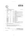
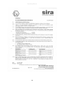
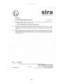
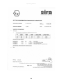
Operating Manual
iCAM100
Operating Manual
This page is intentionally left blank.
Document Number 302803 (See Last Page for Revision Details)
©2006 Extronics Limited. This document is Copyright Extronics limited.
Extronics reserve the right to change this manual and its contents without notice, the
latest version applies.
2
Operating Manual
Contents
1
2
Introduction.......................................................................................................... 4
Safety Information and Notes .............................................................................. 5
2.1
Storage of this Manual ................................................................................. 5
2.2
List of Notes ................................................................................................. 5
2.3
Gland Special Conditions ............................................................................. 6
2.4
Camera Module Special Conditions ............................................................. 6
3 Installation & Setting To-Work ............................................................................. 7
3.1
Wiring ........................................................................................................... 7
3.2
Mounting the Camera using the Wall Bracket .............................................. 8
3.3
Pan and Tilt Adjustment ............................................................................... 9
3.4
Mounting the Camera Directly ...................................................................... 9
4 Operation........................................................................................................... 10
4.1
CCTV Colour Camera ................................................................................ 10
4.1.1
Power Supply Unit............................................................................... 10
4.1.2
Video Line Driver................................................................................. 10
5 Intended Purpose Usage................................................................................... 11
5.1
Transportation and Storage........................................................................ 11
5.2
Authorized Persons .................................................................................... 11
5.3
Cleaning and Maintenance......................................................................... 11
5.4
Safety Precautions ..................................................................................... 12
5.5
Cleaning and Maintenance Intervals .......................................................... 12
5.6
Aggressive substances and environments ................................................. 12
5.7
Exposure to external stresses .................................................................... 12
6 Technical Data .................................................................................................. 13
6.1
Field of View............................................................................................... 13
6.2
Power Supply Input .................................................................................... 14
6.3
Video Signal Output ................................................................................... 14
6.4
CCTV Camera Module Mechanical Details ................................................ 14
6.5
CCTV Camera Module Electrical Details.................................................... 15
6.6
Reliability .................................................................................................... 15
7 Maintenance & Fault Finding............................................................................ 16
7.1
Maintenance............................................................................................... 16
7.2
Fault Finding............................................................................................... 16
8 Type Codes ....................................................................................................... 17
9 EC Declaration .................................................................................................. 18
10
ATEX Certificates........................................................................................... 19
11
Manual Revision ............................................................................................ 34
3
Operating Manual
1 Introduction
The iCAM100 is designed for use in Hazardous areas where a method of surveillance
is required and space is at a premium. It is also ideal for monitoring plant or areas
which are difficult to view due to its compact size. The iCAM100’s design means that it
is suitable for use in both Zone 1 and Zone 2 environments.
Please read the installation and operating instructions from cover to cover before
installing and commissioning the iCAM100. Only Qualified personnel that are authorised from
the operating company should install the iCAM100 unit.
Validity of Operating and Programming Instructions
•
Your Extronics agent will be able to give you information about any improvements or
modifications.
•
If the iCAM100 is damaged by inappropriate use, the manufacturer will not guarantee
the product.
Operational Safety
•
The iCAM100 Module is assembled on our ISO 9000 accredited premises and
therefore conforms to the appropriate requirements.
•
The front of the actual camera housing is protected to IP 66. The termination
enclosure is rated to IP 65.
•
If the iCAM100 is not used in a manner for which it is design or if it is not installed
as directed, there will be a certain level of risk involved for which Extronics Ltd will
not be responsible.
Repairs, Dangerous Chemicals
A note describing the fault must always accompany equipment sent to Extronics Ltd for
repair.
Important!
The following procedures must be carried out before the iCAM module is
returned for repair:
•
Remove all residues that may be present. Pay special attention to the gasket grooves
and crevices where residue may collect.
•
Please ensure that full precautions have been taken to remove all traces of
substances that may represent a health risk before returning any equipment.
Costs of disposal of materials or of injury to personnel (acid burns etc.) arising
because of defective cleaning of the equipment will be charged to the owner of the
equipment.
4
Operating Manual
2 Safety Information and Notes
2.1 Storage of this Manual
Keep this user manual safe and in the vicinity of the device. All persons who have to work on
or with the device should be advised on where the manual is stored.
2.2 List of Notes
The notes supplied in this chapter provide information on the following.
• Danger / Warning.
o Possible hazard to life or health.
• Caution
o Possible damage to property.
• Important
o Possible damage to enclosure, device or associated equipment.
• Information
o
Notes on the optimum use of the device
Warning!
The unit is not to be opened if the immediate area around the came is
classed as explosive.
Warning!
Work on electrically live parts, except for intrinsically safe circuits, is
prohibited on the principle that they’re danger of explosion.
Important
Changes to the design and modifications to the equipment are not
permitted.
Important
Before setting the unit to work, read the technical documentation
carefully. Only the latest version is valid.
Important
Installation, maintenance and cleaning of the units must only be
performed by persons trained and authorized for this purpose.
Important
If it can be assumed that safe operation is no longer possible, switch off
the unit and secure it against being used again.
Important
After de-energising, delay 1 minute before opening
5
Operating Manual
2.3 Gland Special Conditions
Important
The Gland is only suitable in the temperature range of -60°C to +80°C
Important
When the gland is used for increased safety or dust protection, the entry
thread shall be suitably sealed to maintain the ingress protection rating
of the associated enclosure
Important
When used with unarmoured or braided cable, the gland is only suitable
for fixed installations, the cable for which must be effectively clamped to
prevent pulling and twisting
2.4 Camera Module Special Conditions
Important
The free end of the permanently connected cable shall be protected in
accordance with EN50014:1997 clause 14.1.
Important
In accordance with EN 50018:2000 clause 13.4.2 the rear end of bushing
shall be protected by fitting it into a suitably certified enclosure. In
addition, the bushing must not be subject to torque during installation.
Improtant
The product shall not be connected to portable equipment.
Important
The product that is fitted with a window has only been subjected to
reduced risk impact tests in accordance with EN 50014:1997 clause
23.4.3.1; therefore it shall not be mounted in an area where there is a
high risk of impact.
Important
The product shall be earthed in accordance with EN 50014:1997 clause
15 when fitted to a suitably certified enclosure
6
Operating Manual
3 Installation & Setting To-Work
The iCAM100 is very simple to install and can either be secure directly to suitable surface
using the mounting holes on the module, or using the included wall bracket
3.1 Wiring
Remove the iCAM100 lid by undoing the four screws (being careful not to loose the
washers).
Inside you will find a terminal block with four wires going to the camera unit, one twisted pair
for power to the camera & one twisted pair for the video signal.
Using a suitable cable feed through the gland connect the wires to the terminal block as
shown in the diagram.
Note:
For 3 wire Camera Modules the Black wire is common for both the 0V
Supply and the –Video Signal
Yellow & Black for composite output
Pink & Yellow for Differential output
Earth terminal for incoming earth on some models
Once the terminal wires have been connected, tighten the gland and replace the lid
accordingly.
Important
Ensure the correct Cable and Cable Gland are used and that the unit is
suitably earthed for your particular application
7
Operating Manual
Caution
Check wiring before switching on.
3.2 Mounting the Camera using the Wall Bracket
Using the template supplied with each bracket, drill 3 x 7 mm Diameter holes each 45mm
deep and clean out the holes.
Insert one raw plug into each hole
Pass a screw through each hole in the bracket and into the raw plug. Tighten all screws
firmly.
Attach the mounting plate to the iCAM100 module using the bolts and washers supplied
Then attach the plate to the Wall bracket, and tighten all nuts firmly.
8
Operating Manual
3.3 Pan and Tilt Adjustment
To adjust the pan and tilt loosen the nut and bolt on the underside of the bracket, angle the
camera to the required position and tighten the nut and bolt accordingly.
3.4 Mounting the Camera Directly
The iCAM enclosure has four mounting holes located on its underside, which can be used to
mount the camera directly or to the mounting plate for use with the wall bracket.
9
Operating Manual
4 Operation
Once the iCAM100 is wired up all the unit requires is power and a suitable monitor to view
the picture. There are no other adjustments on the camera itself apart from pointing the
camera in the required direction using the pan and tilt.
The iCAM100 does not require manual focusing, however it should be remembered that the
optimal focal distance is dependent upon the lens used for the field of view.
The primary function of the camera is to provide video surveillance monitoring in classified
hazardous areas, such as Zone 1. This is achieved by housing the camera electronics in an
ATEX certified enclosure.
When power is applied to the camera it turns ON and immediately begins video transmission.
4.1 CCTV Colour Camera
The CCTV camera is a self-contained unit with integrated fixed focal length optical lens,
imaging sensor, automatic IRIS and video image generator.
4.1.1
Power Supply Unit
The power supply converts a nominal 24Vdc into two voltage supplies (+/-9Vdc) used
internally to energise the CCTV Colour Camera and Video Line Driver; all supplies have a
common ground (GND) connection.
4.1.2
Video Line Driver
The video line driver converts the 1V composite video output from the CCTV Camera into a
2V differential composite video signal (balanced line) suitable for transmission over either a
75R coaxial cable or 150R twisted pair cable.
10
Operating Manual
5 Intended Purpose Usage
Important
Before setting the units to work, read the technical documentation
carefully.
Important
The latest version of the technical documentation or the corresponding
technical supplements is valid in each case.
The iCAM100 is built using modern components and is extremely reliable in operation;
however it must only be used for its intended purpose. Please note that the intended purpose
also includes compliance with the instructions issued by the manufacturer for installation,
setting up and service.
Any other use is regarded as conflicting with the intended purpose. The manufacturer is not
liable for any subsequent damage resulting from such inadmissible use. The user bears the
sole risk in such cases.
5.1 Transportation and Storage
All iCAM100 devices must be so transported and stored that they are not subjected to any
excessive mechanical stresses.
5.2 Authorized Persons
Only persons trained for the purpose are authorized to handle the iCAM100; they must be
familiar with the unit and must be aware of the regulation and provisions required for
explosion protection as well as the relevant accident prevention regulations.
5.3 Cleaning and Maintenance
The iCAM100 and all its components require no maintenance and are self-monitoring. All
work on the iCAM100 by personnel who are not expressly qualified for such activities will
cause the Ex approval and the guarantee to become void.
11
Operating Manual
5.4 Safety Precautions
Important
For the installation, maintenance and cleaning of the units, it is
absolutely necessary to observe the applicable regulations and
provisions concerned with explosion protection (EN 50014, EN 6007914:2003) as well as the Accident Prevention Regulations.
5.5 Cleaning and Maintenance Intervals
The cleaning intervals depend on the environment where the system is installed.
5.6 Aggressive substances and environments
The iCAM100 is not designed to come into contact with aggressive substances or
environments, please be aware that additional protection may be required.
5.7 Exposure to external stresses
The iCAM100 is not designed to be subjected to excessive stresses e.g. vibration, heat,
impact. Additional protection is required to protect against these external stresses.
The iCAM100 will require additional protection if it is installed in a location where it may be
subjected to damage.
12
Operating Manual
6 Technical Data
Power Supply
19 to 32 V dc 1.2 W ,reverse polarity protected. 36 V over
voltage protection
Electrical Connection
Screw terminals for cables up to 2.5mm
Outputs
PAL composite video
Entries
1 x M20 for suitable Ex e glands
Weight
650 g
Mounting
Universal wall mounting bracket with 360 degree
horizontal pan and 70 degree vertical tilt
Field of View
Range 10 to 150 Degrees. See ordering information for
further details
Light Sensitivity
0.5 Lux @ F2 5600K
Resolution
Picture Element (Pixels) N:290K P:320K, Horizontal res
380 lines
Material
Camera 316L stainless steel, Junction Box GRP
Dimensions
Camera 50mm x 80mm (Dia x l), Junction Box 80mm x
55mm x 75mm (w x h x d)
Ambient Temperature
-20°C to +50°C
IP Rating
IP55
Certification Type
II 2G EEx de IIC T6
Certification Number
Sira 02ATEX1271X
6.1 Field of View
Angle of View
19°
28°
40°
53°
80°
92°
130°
Focal Length
16.0mm
12.0mm
8.0mm
6.0mm
4.0mm
3.6mm
2.97mm
Recognisable Distance
30M
16M
12M
8M
6M
4M
3.5M
13
Best Picture Distance
12M
6M
4M
2.3M
2M
1.8M
1.5M
Operating Manual
6.2 Power Supply Input
Supply
Specification
Supply Voltage
Range
Absolute Voltage
Limits
Supply Power
Consumption
Units
Min
Max
V
19
32
V
14
36
mW
--
1200
Units
Min
Max
Vpp
1
Composite into 75R
Vpp
2
Composite into 150R
(Alternative output
iCAM100-[#1]-D-[#3])
M
500
6.3 Video Signal Output
Video Signal
Specification
Coaxial
Composite
Signal
Differential
Twisted Pair
Typical distance
(PSU/cable
dependant)
6.4 CCTV Camera Module Mechanical Details
Housing
Specification
Operating
Temperature
Range
Operating
Humidity Range
Storage
Temperature
Storage Humidity
Range
Units
Min
Max
C
-20
+50
%RH
0
99 Non condensing
C
-20
+70
%RH
0
99 Non condensing
14
Operating Manual
6.5 CCTV Camera Module Electrical Details
Video Sensor
Specification
Sensor type
Units
Min
Max
Video Signal (EU)
PAL
Light Sensitivity
Lux
290 (H) x 320(V)
380 lines, 50 fields/sec
0.5Lux @ F2 5600ºK
Signal to Noise
Ratio
Lens Field of View
(FOV)
Focus
Iris
db
48
degrees
Select fixed board type lens from 9 to 90
Full Colour (PAL sensor)
Fixed
Automatic
6.6 Reliability
Reliability
Mean Time
Between Failure
Units
Hrs
Min
80,000
Max
15
Operating Manual
7 Maintenance & Fault Finding
7.1 Maintenance
Note:
The iCAM 100 does not require any active maintenance, if however the
iCAM 100 enclosure is opened, it is necessary to ensure that the lid is
replaced correctly and securely, otherwise the iCAM may not comply
with the ATEX regulations.
It is recommended that the iCAM 100 is regularly inspected for deterioration caused from
wear and tear, accidental damage, rust, corrosion of chemicals etc. This is to ensure the
integrity of the protection is maintained at the intended level of security from ignition in
compliance with ATEX regulations.
7.2 Fault Finding
Symptoms
No Video Picture
Cause
No Power Connection
Corrective Action
Ensure that the power supply is connected
properly
Ensure that the video output connections
are connected properly
Ensure the video cables are connected to
the correct video signals from the camera
Ensure that the camera enclosure is
connected to a clean earth Ensure that the
cable screen is connected to a clean earth
at the one end only (generally the video
equipment/monitor) Ensure that all
electrical connections and terminals are
properly made-off and tight
Ensure that the video signal cables are not
run parallel to or mixed in with other high
power/frequency signals Ensure that the
video signal cabling does not run nearby
any high power switching or transforming
equipment
Return to the manufacturer
No Video Signal
Video Picture
Corrupted (Noise)
Video Signal Polarity
Wrong
Poor Video Cabling
Interference
Video Picture
Blurred
Camera Out Of Focus
Camera Optics Fouled
Video Picture Too
Dark
Low Light Level
16
Clean with a suitable optical glass cleaner
or using weak solution of detergent and
water
In dark or low light areas the video picture
quality will reduce and the picture will
become dark – consider installing
conventional or Near-IR light sources
Operating Manual
8 Type Codes
Compact Colour CCTV Camera
Specify Field of View [#1]
Angle of View
Focal Length
iCAM100-[#1]-X-P-[#4]
Recognition
Distance
30M
16M
12
8M
6M
4M
3.5M
Best Picture
19°
16.0mm
12
28°
12.0mm
6
40°
8.0mm
4
53°
6.0mm
2.3
80°
4.0mm
2
92°
3.6mm
1.8
130°
2.97mm
1.5
Specify Cable Entries [#4]
One M20 EEx de Cable Gland, Cable O/D range 3mm - 8mm
Two M20 EEx de Cable Gland, Cable O/D range 3mm - 8mm
Specify Accessories
Wall mounting bracket with manual pan and tilt
17
19
28
40
53
80
92
130
1
2
iCAM100-WB
Operating Manual
9 EC Declaration
18
Operating Manual
10 ATEX Certificates
Junction
box
19
Operating Manual
20
Operating Manual
21
Operating Manual
22
Operating Manual
23
Operating Manual
24
Operating Manual
25
Operating Manual
26
Operating Manual
Camera Module
27
Operating Manual
28
Operating Manual
Cable Gland
29
Operating Manual
30
Operating Manual
31
Operating Manual
32
Operating Manual
33
Operating Manual
11 Manual Revision
Revision
11
12
13
14
15
16
Description
Changed manual to new format
Changed technical information
Updated ATEX Certificate on Camera Module
Amended ordering information
Removed NTSC Option
Changed Cable Gland Type
Date
23/10/07
13/03/08
02/05/08
21/05/08
09/07/09
04/05/10
By
James Eastwood
James Eastwood
James Eastwood
James Eastwood
James Eastwood
James Eastwood
Nick
Saunders
34
Digitally signed by Nick Saunders
DN: CN = Nick Saunders, C = US
Reason: I have reviewed this
document
Date: 2010.05.04 13:45:42
+01'00'


![Di28.manual_eng [更新済み]](http://vs1.manualzilla.com/store/data/006248510_1-4715480d32b4655833aa4eb8b5d462bc-150x150.png)