1
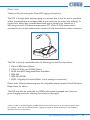
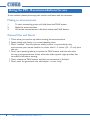
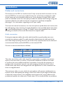
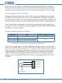
PM1
Paging Microphone
Installation and User Guide
Contents
Introduction....................................................................4
Safety Information.................................................................................... 4
Overview.................................................................................................... 5
Scope of this guide................................................................................... 6
What’s in the box..................................................................................... 6
PM1 components...................................................................................... 7
Using the PM - Recommendations for use..................8
Making an announcement....................................................................... 8
General Dos and Don’ts......................................................................... 8
Installation......................................................................9
Cables and connections.......................................................................... 9
Audio connection................................................................................. 9
Control (paging access) connection............................................... 10
Cable lengths....................................................................................... 12
Grounding issues................................................................................ 12
Specifications............................................................... 13
Microphone frequency response......................................................... 14
Microphone polar plot.......................................................................... 14
Notes............................................................................ 15
Introduction
Safety Information
The Cloud PM1 contains no active electronics and thus requires no AC or DC
voltage supply. Safety precautions are therefore minimal.
However, note that both the metal base of the unit and the mic gooseneck will be
electrically connected to the chassis of the host device (e.g. Cloud zoner or mixer/
amplifier) once the installation is carried out. This means that if the mains wiring of
the host device and/or the building is faulty, the microphone could present a shock
hazard. Fitting a suitable earth leakage circuit breaker (e.g. 30 mA RCD type) to the
mains supply of the host device can provide additional protection.
4
PM1 Installation and User Guide v1.0
Overview
Thank you for purchasing this Cloud PM1 paging microphone.
The PM1 is a single-zone, passive paging microphone; that is, one for use in situations
where announcements are always made to the same area (or areas) of a building*. It
consists of a heavy-duty moulded base fitted with a dynamic mic capsule on a 300 mm gooseneck. The base incorporates a PTT (Press To Talk) button which
unmutes the mic and provides switch contacts for the host device’s access connector.
The PM1 is directly compatible with the following current Cloud products:
• Z4ii and Z8ii Venue Mixers
• CX163, CX261 and CX263 Mixers
• 36/50 and 46/50 Integrated Mixer Amplifiers
• MPA-626
• MPA 60/120/240
• DCM-1 Digitally-Controlled Mixer (via its analogue connection)
Other, older Cloud products may also be compatible; please contact Cloud’s Technical
Department for advice.
The PM1 may also be used with any OEM audio system equipped with ‘short-toground’ paging access for selecting the zone(s) to be paged.
*Other models in the PM range are available which permit announcements to be made to specific areas
of a building – these are termed “multi-zone” paging microphones. Please contact your Cloud dealer/
distributor for more information
PM1 Installation and User Guide v1.0
5
Scope of this guide
The primary purpose of the guide is to describe the connection of the PM1 to a host
zoner or mixer/amplifier. For the benefit of the user, a section of ‘recommendations
for use’ is also included.
What’s in the box
• Cloud PM1 paging microphone
• Installation and User Guide (this manual)
If any items are received in a damaged state or are missing from the packaging, please
contact your Cloud dealer/distributor at once. Wherever possible, please retain the
packaging until the microphone is satisfactorily installed and working, in case it needs
to be returned to the factory.
6
PM1 Installation and User Guide v1.0
PM1 components
2
1
1
2
3
Microphone capsule
Flexible gooseneck
PTT (Press To Talk) button
3
4
13
6
5
11
9
7
10
12
8
PM1 internal
PM1 baseplate
4
5
6
7
Cable access holes
Rubber feet (x3)
Base securing screws (x5)
Screws for internal cable clamps (x4)
8
9
10
11
12
13
Cable clamps (x2)
Microphone output connector (audio signal)
Access control connector
Jumper for ground interconnection (see text)
Mic capsule cable
PTT (Press To Talk) button
PM1 Installation and User Guide v1.0
7
Using the PM - Recommendations for use
To the installer: please photocopy this section and leave with the customer.
Making an announcement
1.
2.
3.
To start announcing, press and hold down the TALK button.
Make the announcement.
When the announcement is finished, release the TALK button.
General Dos and Don’ts
• Think what you need to say before making the announcement.
• Speak slowly and clearly in a normal speaking voice.
• Don’t “swallow” the microphone; unless you are in a particularly noisy
environment your mouth need be no closer than 4 - 5 inches (10 – 12 cm) from
the mic.
• Don’t start speaking before you press the TALK button, and then also wait
for any pre-announcement chime which the audio system might produce has
sounded in full before starting.
• Don’t release the TALK button until the announcement is finished.
• Don’t twist the gooseneck into odd shapes – it isn’t a toy!
8
PM1 Installation and User Guide v1.0
Installation
Cables and connections
Connections to the PM1 are made via two 3-way screw-terminal connectors on the
internal PCB. Two cut-outs are provided at the rear of the base moulding for cable
access; these can accommodate cables up to 9 mm diameter. A single 2-pair cable
(with an individual screen for each pair) provides the neatest finish, though using two
separate cables for the audio and access connections is perfectly acceptable (see page 11 for information regarding use of 2-pair cable).
To access the internal connectors, turn the microphone upside-down and remove the
five self-tapping screws securing the steel baseplate to the moulded plastic base (item
6 in the baseplate diagram on page 7). Gently remove the baseplate from the base
moulding; be careful not to strain the internal mic capsule cable.
Audio connection
If using two separate cables, the audio cable should be a good quality, two-core,
screened microphone cable. The cable should be fed through the left-hand of the
two cable clamps (looking from the rear of the unit), and connected to the left-hand
screw-terminal block (marked AUDIO) on the internal PCB.
Connect to the terminal block as follows:
TERMINAL
USE
TYPICAL CABLE COLOUR
Hot
Phase (+)
Red
Cold
Anti-phase (-)
Black
Screen
Screen (Scn)
Screen
The other end of the audio cable should be connected to a suitable microphone
input on the host mixer (or zoner). Consult the Installation Guide for the mixer
to confirm the most suitable method of connection. It may also be necessary to
configure the microphone input for use with a paging microphone. As all recent
Cloud mixers and zoners are designed with this application in mind, connection to
them is straightforward.
The maximum cable run over which the microphone will operate satisfactorily is a
function of the cable quality, the design of the host mixer’s input stage and the level
of electrical noise present in the installation environment. As rough guidance, with
professional-quality mic cable and a Cloud mixer, 100 m should present no problems.
PM1 Installation and User Guide v1.0
9
Note that the mic capsule is a dynamic type and no phantom power is required.
Ensure that the microphone input used does NOT have phantom power enabled as
damage to the capsule may result from the inadvertent application of a DC voltage.
Control (paging access) connection
If using two separate cables, the control cable may be any suitable two-core cable,
though the use of single-core or twin-core screened cable is preferred (especially if
the microphone is more than a few metres from the host mixer). Many installers will
choose to use a second run of microphone cable, which provides a neat appearance.
The control cable should be fed through the right-hand cable clamp (looking from
the rear of the unit), and connected to the right-hand screw-terminal block (marked
ACCESS) on the internal PCB.
Connect to the terminal block as follows:
TERMINAL
USE
TYPICAL CABLE COLOUR
0V/COMMON
Switch common contact (C)
Screen
ACCESS N/C
Switch normally-closed contact (NC)
ACCESS N/O
Switch normally-open contact (NO)
Core*
*Connect the core to either N/O or N/C, not both. See following text.
Connect the control cable to the 0V/COMMON terminal and either the ACCESS
N/C or the ACCESS N/O terminal. The PTT (Press-To Talk) switch is fitted with both
types of contact (see diagram below); use whichever the host mixer’s Access Port
requires (consult the Installation Guide for the mixer to confirm the convention
used). All Cloud mixers and zoners require the use of external NO contacts for
paging access, so use the ACCESS N/O terminal if connecting the PM1 to a Cloud
host unit.
U3
NO
C
NC
ACCESS N/O
ACCESS N/C
0V/COMMON
PRESS TO TALK
10
PM1 Installation and User Guide v1.0
The other end of the control cable should be connected to the host mixer’s Access
Port. It may be necessary to configure the mixer for correct operation with a paging
microphone. Mixers/zoners with more than one microphone input will probably have
an Access Port catering for each input; be sure to connect the control cable to the
terminal related to the microphone input being used. Again, all recent Cloud mixers
and zoners are designed for use with paging microphones and connecting to and
configuring them is straightforward.
Typical example
The example shown below illustrates the connection of a PM1 to a Cloud CX261
mixer. It is assumed that MIC 1 input is used.
PM1
CLOUD CX261
U3 ACCESS
ACCESS PORT
N/O
M2
N/C
M1
0V
0V
SCREEN
1
COLD
2
HOT
3
U2 AUDIO
MIC 1 INPUT
In the example, 2-pair cable is employed, with separate screened twin-and-screen
cores for the Audio and Access connectors. The PM1’s audio output is wired pin-topin to the MIC 1 INPUT connector on the CX261. The access connector is wired to
the CX261’s Access Port, the ground terminal being connected to 0V on the host via
the cable screen and the N/O terminal to M1.
Use this same wiring arrangement if using two separate cables.
In addition, the CX261’s internal jumpers will need to be set to enable the Access
Port and to set the Mic 1 priority circuit for access triggering. The CX261’s own User
Guide fully describes this procedure. It is likely that similar adjustments will need to
be made with all makes and models of host mixer; the unit’s documentation should
be consulted in all cases.
PM1 Installation and User Guide v1.0
11
Cable lengths
The maximum permissible length of cable between the PM1 and the host mixer is
dependent on the quality of the cable(s), the input of stage of the mixer and the
general electrical environment in the building. However, as rough guidance, it should
work satisfactorily with cable runs up to 100 m when connected to a well-designed
mic input stage (such as found in the Cloud CX Series) with professional microphone
cable.
Grounding issues
As the PM1 is a passive microphone, hum and buzz problems due to grounding will
be rare. Always ensure that the screen of the microphone cable is connected at both
ends. In a very few circumstances with third-party mixers, it may be necessary to join
the ‘common’ terminal of the mixer’s Access Port to the audio ground; this can be
accomplished by shorting the pins of J1 on the internal pcb with the jumper provided.
12
PM1 Installation and User Guide v1.0
Specifications
MICROPHONE
Type
Dynamic, Cardioid
Frequency Response
80 Hz – 15 kHz
Sensitivity
-54 dB ±3 dB (0 dB = 1 V/Pa at 1 KHz)
PTT SWITCH
Type
Momentary
Contacts
NO and NC
CONNECTIONS
Audio
Balanced, 3.5 mm-pitch screw terminals
Control
NO/NC, 3.5 mm-pitch screw terminals
Cable Access
At rear, 9 mm max. dia., internal retention
PHYSICAL
Base dimensions (W x D x H)
150 x 150 x 43 mm
Gooseneck length (inc capsule)
312 mm
Weight
430 g
PM1 Installation and User Guide v1.0
13
Microphone frequency response
Source level: 0.1 Pa
Measurement distance: 50 cm
Test instruments: Bruel & Kjaer 2012 & 9640
0°
Microphone polar plot
Source level: 0.1 Pa
Frequency: 1000 Hz
Measurement distance: 50 cm
Test instruments: Bruel & Kjaer 2012 & 9640
14
PM1 Installation and User Guide v1.0
180°
Notes
PM1 Installation and User Guide v1.0
15
Cloud Electronics Limited
140 Staniforth Road, Sheffield. S9 3HF. England
Tel: +44 (0)114 244 7051 Fax: +44 (0)114 242 5462
email: [email protected] web: www.cloud.co.uk