1
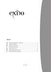
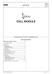
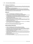
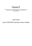
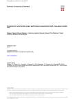
UNIVERSAL MANIFOLD TYPE K7037
Installation and User Manual
INDEX
1.
2.
3.
4.
5.
6.
7.
8.
9.
10.
11.
CONTENTS
INSTALLATION STANDARDS
PLACING THE PIPES
CONNECTING THE PIPES
CONNECTING THE MIXING UNIT
FILLING AND AIRING THE SYSTEM
TEST OF WATERTIGHTNESS
BALANCING THE SYSTEM
8.1 DIAGRAM FOR REGULATION
8.2 PRESSURE DORP DIAGRAM
8.3 FLOOR HEATING BALANCING
CONNECTING THE ACTUATORS
WIRED CONTROL SYSTEM
WIRELESS CONTROL SYSTEM
1. CONTENTS
The Pettinaroli universal manifolds K7037 are made of extruded brass type
Cw614N.
The Pettinaroli manifold system is delivered with 2 to 8 outlets. The manifold
is mounted on wall brackets and are delivered with a terminal set, manual air
vent, drain-fill ball valve and thermometer. The upper manifold is for the inlet
water. The manifold below is for the outlet water. The manifold is delivered
with integrated control Valves. The control valves are delivered with manual
hand wheels for regulation.
2. INSTALLATION STANDARDS
The heating system has to be regulated according to the current standards, which you find in the regulations for buildings. And according to the standards for heating systems in your country.
The basics are the heat loss in the house, the way you place the pipes in the floor and the choosen construction of the floor. The floor heating pipe has to be placed in the floor according to the instructions for
the choosen construction.
3. PLACING THE PIPES
For radiator installations the tubes will be placed, without hidden collections from inlet-manifold to the
radiator and correspondingly from the radiator to the outlet-manifold.
To achieve the most optimal comfort in the room, the pipes have to be
placed in the floor after the standard principles. If there have been made
drawings of the installation, the pipes have to be placed according to
those drawings.
To achieve the best result – planning how to place the pipes in the floor
is very important.
Before placing the pipe you have to connect the pipe to the inlet manifold. When the pipe has been placed, the end of the pipe will be connected to the outlet manifold. Placing the pipe has been completed.
4. CONNECTING THE PIPES
Lead the pipe to the upper bar. Cut of the pipe at the right length. It is important with a sharp and straight
cut. Place the fitting at the pipe and connect it to the manifold.
Connect the heating system with ball valve of type 52MET 1”x ¾”. If you want to circulate water with a
lower temprature, than comes from the suppling system, you have to mount a mixing kit as descriped in
sec. 5.
5. CONNECTING THE MIXING UNIT
To achieve the most optimal comfort in the room and the best solution saving money at energy costs, it is
very important that the system will be supplied with water at the right temperature.
The correct temperature can be calculated in the program which you will be able to find at our web-site
www.pettinaroli.dk. If the heating source can´t ensure the correct temperature, it will be necessary to
connect a mixing unit to the system.
Remember gasket
Alpha+ pump
Constant pressure area
By using a floor heating system, the pump has to be set within a
constant pressure area, as indicated above.
7021
The mixing unit 7021 with Grundfos Alpha2 pump, has to be mounted on the left side of the manifold.
The calculated temperature will be regulated by the thermostat.
If there is no room for the mixing unit in connection with the manifold, it is possible to mount it with an
angle set art. ACC7021.
6. FILLING AND AIRING THE SYSTEM
Filling and airing the system has to be done very systematic. Air in the system can give you problems
regulating the system and in worst case burn of the pump.
6.1.
Connect a hose to the upper bar and fill in water and lead air/water out of
the return manifold with another hose.
6.2.
Turn off the thermostat and the return valve
6.3.
Turn off the balancing and thermostatic valves on the manifolds
6.4.
Turn on the water on the upper bar and open for the drain valve on the bar below
6.1
6.2
6.3
6.4
6.5
6.7
6.5.
Turn on the circuit which is longest from the mixing unit. Keep filling in water until no
more air comes out of the drain valve. Now you can turn off the first circuit.
6.6.
Repeat this procedure circuit by circuit, until all circuits have been filled with water and
drained for air.
6.7.
Dismount the hoses and replace the caps on the drain/filling valves. Remember to save
the hose connector
7. TEST OF WATERTIGHTNESS
When testing the tightness all valves have to be in open position. If there is any possibility of freezing
water, then add glycol or something similar to avoid the pipes busting. The glycol shall be washed out of
the system before it is started.
7.1.
Floor heating pipes
The pipes have to be tested for tightness when they still are visible. If nothing else has been specified the
pipes have to be tested by 0,6MPa (6Bar). Keep the pressure for 30 minutes and check that all connections are tight. Then lower the pressure to 0,3MPa (3Bar). Keep this pressure for 2 hours, without dropping the pressure on the system.
7.2.
Report
A report has to be prepared form the results of the pressure test. Keep this report with other manuals for
the heating system of the house.
7.3.
Concreting
By concreting, the pipes have to be under pressure to avoid damage on the pipes during the work. If there
is any risk of freezing pipes, add glycol or something similar until the work has been ended.
7.4.
Other types of floor
It is always recommendable to keep the pipes under pressure to avoid damage and leaks from the pipes
during the work.
8. BALANCING THE SYSTEM
To achieve the most optimal function of the heating system, it is very important that the manifold will be
regulated with the correct flow of the heating system.
Balancing the floor heating circuits can be done in 3 different ways.
8.1 Diagram for regulation:
- 20 x 2 mm PE pipes
- 12 mm Evoflex pipes
Balancing with the quick regulation schemes:
Read the instruction at the next page.
QUICK - INSTALLATION FOR FLOORHEATING
INSTALLATION OF UNIVERSALMANIFOLD
20 X 2 MM FLOOR HEATING
OTHER CIRCUITS
LONGEST FLOOR HEATING CIRCUIT
m
120
100
80
60
40
120
6
100
5
6
80
4
5
6
60
3
4
5
6
40
2
3
4
5
6
20
1
2
3
4
5
20
6
12 MM EVOFLEX PIPES
OTHER CIRCUITS
LONGEST FLOOR HEATING CIRCUIT
m
70
70
6
60
50
40
30
20
60
5
6
50
5
5
6
40
4
4
5
6
30
3
3
4
5
6
20
2
2
3
3
5
6
10
1
1
2
2
3
4
10
6
The longest pipe has always to be completely open
INSTRUCTIONS:
1.
2.
3.
4.
The longest pipe has to be completely open
Choose the colum which contains the longest pipe
Find the line for the pipes which should be regulated
Read in the column for the longest pipe, in which position the indicator
have to be
EXAMPLE:
Longest pipe = 100m / pipe 2 = 80 m / pipe 3 = 20 m
Incolumn for 100 m and for line of 80 m you can read that the regulation for the
second pipe is a position of 5
OTHER CIRCUITS
In the same way you can read the regulation for the therd pipe has a position of 1
LONGEST FLOOR HEATING CIRCUIT
m
120 100
80
60
40
120
6
100
5
6
80
4
5
6
60
3
4
5
6
40
2
3
4
5
6
20
1
2
3
4
5
20
6
Pressure drop (kPa)
Pressure drop mmH2O
8.2 Pressure drop diagram
8.3 Floor heating program
K7037UNIVERSALFORDELER
PETTINAROLI
Projekt:
Sign.:
Dato:
Bygning
Gulvvarmerør
Temperaturniveau
Krets Rum
Areal
CC
Type Gulvrør Tur/Retur Ialt Rørtab Rum Effekt
ȴt Frem
No
Navn
m²
cm
mm
m
m
m mVS
°C
W/m²
°C
°C
13
1
0
20 12x1,3
1
0
0
0
0,00 20 50
50 5
31,5
13
2
0
25 12x1,3
1
0
0
0
0,00 20 50
50 5
31,5
13
12x1,3
3
0
30
1
0
0
0
0,00 20 50
50 5
31,5
13
4
0
#VÆRDI! 12x1,3
1
0
0
0
0,00 20 50
50 5
31,5
20
5
0
#VÆRDI! 16x2
2
0
0
0
0,00 20 50
50 5
31,5
20
6
0
#VÆRDI! 16x2
2
0
0
0
0,00 20 50
50 5
31,5
20
7
0
#VÆRDI! 16x2
2
0
0
0
0,00 20 50
50 5
31,5
20
8
0
#VÆRDI! 16x2
2
0
0
0
0,00 20 50
50 5
31,5
30
9
0
#VÆRDI! 20x2
4
0
0
0
0,00 20 50
50 5
31,5
30
10
0
#VÆRDI! 20x2
4
0
0
0
0,00 20 50
50 5
31,5
30
,
,
11
0
#VÆRDI! 20x2
4
0
0
0
0,00
20 50
50 5
31,5
30
12
0
#VÆRDI! 20x2
4
0
0
0
0,00 20 50
50 5
31,5
30
13
0
#VÆRDI! 20x2
4
0
0
0
0,00 20 50
50 5
31,5
30
14
0
#VÆRDI! 20x2
4
0
0
0
0,00 20 50
50 5
31,5
30
15
0
#VÆRDI! 20x2
4
0
0
0
0,00 20 50
50 5
31,5
16
Ialt
0
m²
0
30
#VÆRDI! 20x2
4
0
0
0
m
0
0
20
50
50
5
31,5
°C
INDSÆT RESULTAT
VarmeͲ
behov
kW
0,0
0,0
0,0
0,0
0,0
0,0
0,0
0,0
0,0
0,0
,
0,0
0,0
0,0
0,0
0,0
0,0
kW
0,0
Trim
Trim
0,0
0,0
0,0
0,0
0,0
0,0
0,0
0,0
0,0
0,0
,
0,0
0,0
0,0
0,0
0,0
0,0
l/min.
Gulv
Type
Konstruk
tion
Parkett
1 Trebjelkelag1
Parkett
1 Trebjelkelag1
Parkett
1 Trebjelkelag1
Parkett
1 Trebjelkelag1
Parkett
1 Trebjelkelag1
Parkett
1 Trebjelkelag1
Parkett
1 Trebjelkelag1
Parkett
1 Trebjelkelag1
Parkett
1 Trebjelkelag1
Parkett
1 Trebjelkelag1
Parkett
1 Trebjelkelag1
Parkett
1 Trebjelkelag1
Parkett
1 Trebjelkelag1
Parkett
1 Trebjelkelag1
Parkett
1 Trebjelkelag1
Parkett
1
Trebjelkelag1
Pettinaroli thermofloor - calculating program and instructions can be down loaded from the following web
site www.pettinaroli.dk
In column “Trim” you can see how many turns you have to open the valve at each circuit at the inlet manifold.
9. CONNECTING THE ACTUATORS
According to the standards DS469, a heating system which is the primary heating souce has to be regulated automaticly. Below it is illustrated how to replace the hand wheels with actuators for controlling the
system.
Dismount the hand wheel
on the thermostatic valve
Place the adaptor on the
thermostatic valve
Click on the actuator at
the adaptor
10. WIRED CONTROL SYSTEM
The system consits of a control system for 1 to 12 heating zones which is controlled by room thermostats
and max. 14 actuators, which regulate the quantity of water supplying the circuits.
Pettinaroli has 230V and 24V systems.
Components for 230V systems have the series number 2000
Components for 24V systems have the series number 4000
The quick guide for installation of the wired control system can be downloaded from our website www.
pettinaroli.dk.
11. WIRELESS CONTROL SYSTEM
BRAVO: The system consits of a 6 or 12 heating zones with a 868MHz signal and max 13 actuators,
which regulate the quantity of water supplying the circuits.
2 zoners
6 zoners
12 zoners
230 V
230 V
230 V
max 4 actuators
max 12 actuators
max 14 actuators
Zone 6 and 7 are resevated for two actuators, meanwhile the other zones are for one actuator.
Make a hole at the bottom of
the control box to feed the
wires from the actuators.
PROGRAMMING OF CONNECT THE
THE THERMOSTAT CONTROL BOX
MOUNTING THE
THERMOSTAT
MOUNT THE
COVER
Mount the control box at the
wanted place
CONNECT THE
ACTUATOR
MOUNT THE CONTROL BOX
For mounting
After programming use the
two screws for mounting the
cover.
CHANGE ZONE
GUIDE TO INSTALLATION OF WIRELESS FLOORHEATING
BRAVO - WIRELESS SYSTEM
SET
Use the screws for mounting
the cover at the control box.
Two screws
OBS OBS OBS OBS
CR 2032
+
Place the two wires in the
terminals as shown at the
box.
1.
2.
SET
3.
Behind the temperature
scale you find the SET-button, and a sticker.
1. Temperature button
2. SET-button 3. Lock for the
cover to the base.
Mount the base at the wall,
on which you can mount the
room thermostat.
Connect the voltage to the
control box with terminal
“Netz” (N and L).
Connect the control box to
the operating voltage.
The actuators are now
making an automatic setting
(8 min.).
TIPS!
By writing the name of the room and
zone at the sticker at each room thermostat you will be able to bring the
thermostats to the control box.
When finishing the programming
you will be able to mount the room
thermostats at the bases again.
IMPORTANT:
Keep the room thermostats min. 1 m
from the control box when programming.
OBS:
Under denne procedure vil dioderne
tænde og slukke for alle zoner.
BEMÆRK:
Når dioden for den pågældende
varmezone holder op med at blinke,
er der opnået kontakt mellem rumtermostaten og styreenheden.
Denne procedure gentages for
samtlige zoner. (Skift zone, se
nedenfor)
SET
SET
SETbutton
knap
Zone 1. Keep the Set-button
down until the diode 1
flashes(5-10 sec.)
Keep the Set-button down
at the room thermostat.
The diode for the zone stops
flashing.
Change zone: Keep the Setbutton dowm until diode 1
flashes.
Press shortly at the setbutton to change for zone
2, 3...
The diode for the zone stops
flashing.
Bilag 3
PETTINAROLI WIRELESS SYSTEM
4 COMMON QUESTIONS:
1.
One or more diodes blinks on the control system after programming the room thermostats.
There is no contact between the room thermostat and the control unit.
A)
The problem can be the following:
To check that the room thermostat is programmed to the right zone, keep the set-button down
for 10 seconds. Is the room thermostat programmed correctly, the following will happen:
The diode on the control unit will turn on the red light (it is calling for heat), then the actuators
will open and close within 15 minutes.
B)
Check that the batteries are placed correctly in the roomthermostat.
C)
Pull out the plug to the control unit and insert again. A self-test will now be running. All diodes
which are programmed to a roomthermostat will now blink, constantly lighten up and then turn
off, if they do not call for heat.
The actuators will open and close, and heat will be sent out in the circuits. This procedure will
last approx. 25 minutes.
If one or more of the diodes blinks after this self-test, it is recommendable to re-programme the
room thermostats, please look in the guide.
D)
The room thermostat can not reach the control unit. Normally the operational range is 25 meters, but some constructive conditions in the building can give some problems. For instance
electronical components and boxes in metal placed close to the control unit. An external anten
na can solve this problem
During programming of the room thermostat, do not touch the print-plate on the back of the roomthermostat. It is also recommendable to keep the room thermostat at least 1 meter from the control unit during
the programming.
2.
How often do you have to change batteries?
The nomal lifetime of the batteries are 3 years. Do not use rechargeable batteries.
OBS: Be careful when you place/replace the batteries.
3.
How can you know that you have to change the batteries?
If a diode starts blinking, there is no contact between the roomthermostat and the control
unit. Is it not possible to activate the room thermostat by pressing down the set-button for
10 seconds (the diode on the circuit will lighten up) it might be the batteries which have to be
changed.
4.
How much power does the system use per year?
Each actuator use 3 Watt during start-up and 2 Watt during operation.
Per actuator : 1750 hours/year à 2 Watt
= 3,5 kWh/year
Notes
__________________________________________________________________________
__________________________________________________________________________
__________________________________________________________________________
__________________________________________________________________________
__________________________________________________________________________
__________________________________________________________________________
__________________________________________________________________________
__________________________________________________________________________
__________________________________________________________________________
__________________________________________________________________________
__________________________________________________________________________
__________________________________________________________________________
__________________________________________________________________________
__________________________________________________________________________
__________________________________________________________________________
__________________________________________________________________________
__________________________________________________________________________
__________________________________________________________________________
__________________________________________________________________________
__________________________________________________________________________
__________________________________________________________________________
__________________________________________________________________________
__________________________________________________________________________
__________________________________________________________________________
__________________________________________________________________________
__________________________________________________________________________
__________________________________________________________________________
__________________________________________________________________________
__________________________________________________________________________
__________________________________________________________________________
__________________________________________________________________________
__________________________________________________________________________
__________________________________________________________________________
__________________________________________________________________________
__________________________________________________________________________
__________________________________________________________________________
__________________________________________________________________________
__________________________________________________________________________
__________________________________________________________________________
__________________________________________________________________________
__________________________________________________________________________
__________________________________________________________________________
__________________________________________________________________________
__________________________________________________________________________
__________________________________________________________________________
IMPORTANT INFORMATIONS CONCERNING THE CONTROL UNIT:
In the plastic cabinet at the control unit a circuit breaker is placed.
It is recommendable to place the room thermostats in a height of 1.50 meter and in a place without direct
sun. If you just place the room thermostat on a closet or a table, the batteries will fall out and you will
loose the connection between the control unit and the room thermostat.
Every 10 minutes each room thermostat will send a signal to the control unit. If the room temperature is
not correct it will call for heat and the diode will lighten up in the control unit. The control unit will open
and close the actuators until the right temperature has been achieved.
The time before the floor heating will react can be several hours.
If the control unit loose the power it will keep the data which has been programmed.
LED frequency of each heating zone for a control system 868MHz:
Blink frequency of diode on the control unit.
Normal operation
Output active
Output not active
AR 4070
Output active
Battery weak
Output not active
receiver signal
Output active
week
Output not active
Independent of the status
of each output
Emergency operation
Programm mode
0
0,5
1
2
Pettinaroli A/S
Mandal Allé 21
DK-5500 Middelfart
Denmark
Tel: +45 6341 6666 • Fax: +45 6341 6660
E-mail: [email protected] • Internet: www.pettinaroli.dk
Rev. 1.1 • Juni. 2011
3