1
Digital Measurement Amplifier
Type DK900
Instructions
for
adjusting and starting
MESOMATIC
Automation und Messtechnik GmbH
Siemensstr. 36
D-71394 Kernen i.R.
Tel. (0)7151 / 94902-0
Fax (0)7151 / 43946
Copyright © 2004 - 2007
by
Mesomatic GmbH
D-71394 Kernen i.R.
Software version 4K
Date 2007-April
Table of contents
1.
Application....................................................... 1
2.
2.1.
2.2.
2.3.
2.4.
2.5.
2.6.
2.7.
2.8.
Configuration..................................................... 2
Profibus DP address............................................... 3
Scale............................................................. 4
Filter............................................................ 4
Zero point........................................................ 4
Adjustment........................................................ 4
Storage of the configuration and calibration data on PC / floppy disk
Storage of the configuration and calibration data in the DK900.... 5
Loading of configuration and calibration data from PC / floppy disk
3.
3.1.
3.2.
3.2.1.
3.3.
3.3.1.
3.3.2.
3.3.3.
3.4.
3.4.1.
3.4.2.
3.4.3.
3.4.4.
3.4.5.
The Profibus-DP interface.........................................
Connection........................................................
Parameterisation of the DK900.....................................
Profibus parameters...............................................
Parameterisation of the Profibus-DP Master........................
Design............................................................
GSD file..........................................................
Consistent reading and writing....................................
The data channels.................................................
Process data channel for inputs (identifier 0x98).................
Bidirectional channel (identifier 0xFF)...........................
Shortened bidirectional channel (identifier 0xBF).................
Slave diagnosis...................................................
The extended identifier (0xC0, 0xFF, 0xFF)........................
4.
Technical data.................................................... 19
5.
Connecting plan................................................... 20
6.
Serial cable...................................................... 22
DK900
I
8
8
8
8
9
9
9
10
12
12
14
17
18
18
5
5
MESOMATIC
Automation und Messtechnik GmbH
D-71394 Kernen
1. Application
The DK900 Measuring Amplifier is a universal instrument for the evaluation of small analog
signals.
Its main field of application is weighing technology where the instrument is operated
together with load cells. As a matter of course, any other sensor with an electric analog
output signal allows to be connected to this amplifier as well.
Distinctive features of the instrument are, among others:
-
DK900
High stability
Excellent resolution
Compact design (top hat rail mounting)
Extremely low power consumption
Optional with Profibus
1
MESOMATIC
Automation und Messtechnik GmbH
D-71394 Kernen
2. Configuration
The configuration and adjustment (start/end adjustment) of the scales is done via a
PC/notebook PC (WIN98 or higher). The respective programme is delivered together with the
instrument, on a floppy disk.
The procedure is as described below:
-
Connect the DK900 to the scales.
Connect the X2 serial interface with the PC (COMx).
Apply an operating voltage of 24 VDC.
Turn on the PC and start the configuration programme (DK900CFG_engl.BAT).
Fig. 1
-
DK900
Select the serial interface to which the instrument has been connected.
2
MESOMATIC
Automation und Messtechnik GmbH
D-71394 Kernen
The current configuration data of the DK900 will now be displayed:
Fig. 2
The fields in the Configuration window must be filled in as follows:
2.1.
Profibus DP address
Enter the instrument address (provided that the PC is equipped with a Profibus). The
address may be between 001 and 125.
DK900
3
MESOMATIC
2.2.
Automation und Messtechnik GmbH
D-71394 Kernen
Scale
Input field
Range of values
or option
Step size
position of dec.
point
1 ú 2 ú 5
-4 ... 1
No. scale
intervals
1
0
-1
-2
-3
-4
#####0
#####
####.#
###.##
##.###
#.####
EndWeight
Steps
100 ... 99999
1st example:
Scales with a capacity of 5000 kg and steps of 2 are to be scaled:
This means the step is 2.
Enter 0 as the decimal point position.
The no. scale intervals is calculated as follows: 5000 / 2 = 2500
2nd example:
Scales with a capacity of 15,000 kg and steps of 5 are to be scaled:
This means the step is 5.
The decimal point position is -3.
The no. scale intervals is calculated as follows: 15000 / 5 = 3000
2.3.
Filter
You may enter a filter depth between 1 ... 30. The value of 20 corresponds to a limiting
frequency of approximately 1 Hz.
2.4.
Zero point
Click the 'set zero point' button with the scales being empty. The actual value determined
by the analog to digital converter (ADC) will be displayed on the right hand side in the
'ADC' field.
Attention:
2.5.
If required,
adjustment.
hang/put
on
the
scales
an
auxiliary
device
before
starting
Adjustment
Enter the adjustment weight in the 'weight' field. This needs not necessarily be the end
weight of the scales.
Hang/put the adjustment weight on the scales/auxiliary device and click the 'calibrate'
button.
By clicking this button the calibration process is started. The raw value determined by the
ADC (max. 7 digits) can be read from the ADC field.
If you did not use an auxiliary device, the adjustment process is now completed. Otherwise
proceed as follows:
Remove the auxiliary device from the scales and click the 'shift zero point' button in the
Zero point section.
DK900
4
MESOMATIC
2.6.
Automation und Messtechnik GmbH
D-71394 Kernen
Storage of the configuration and calibration data on PC / floppy disk
The configuration and calibration data can be stored on the PC, or on a floppy disk, by
clicking the 'store' button in the Configuration file section.
Fig. 3
Select the path/drive desired, enter a file name and click ' Öffnen '.
2.7.
Storage of the configuration and calibration data in the DK900
Click the 'take over' button in order to store the configuration and calibration data in
the DK900.
Click the 'end' button in order to quit the programme and close the Configuration window.
2.8.
Loading of configuration and calibration data from PC / floppy disk
You may load any configuration
Configuration file section.
file
stored
The following display will appear:
DK900
5
by
clicking
the
'load'
button
in
the
MESOMATIC
Automation und Messtechnik GmbH
D-71394 Kernen
Fig. 4
First click the file desired and then click 'Öffnen'.
Click the 'take over' button in order to transfer the file selected to the DK900.
You may use this procedure to replace a defective device by a new one, for example, without
having to perform a re-adjustment with the help of adjustment weights.
DK900
6
MESOMATIC
Automation und Messtechnik GmbH
D-71394 Kernen
3. The serial interface
3.1.
Connection
Data is exchanged between the master computer and the DK910 (slave(s)) via a serial
interface (X2).
The data format is 8N1, with function F 53 the baud rate can be selected between 9600 and
19200 Baud.
3.2.
Commands
Commands consist of an '!'=21Hex=33Dec, followed by the actual command character. When the
DK800 receives a command, it checks whether it is possible to execute it. If so, it answers
with ACK=06Hex=Ctrl-F (acknowledgement) and executes the command. If the command cannot be
executed, it answers with NAK=15Hex=Ctrl-U (negative acknowledgement).
After ACK or NAK has been sent back, the DK910 disconnects the communication.
The basic timing is as follows:
1. DK910 receives the command (or data).
2. It checks whether the command is executable.
3. It answers with a ACK- or NAK-character.
4. It starts the execution of the command.
3.2.1.
Net (Taring)
Taring is carried out to the command:
!N
(21Hex & 4EHex)
Reply:
ACK = The DK)!0 displays the net weight.
NAK = Taring is not possible, e.g. the weigher is in motion.
Taring can be executed a number of times in sequence without the unit switching back to
"gross" mode.
3.2.2.
Gross
The gross command cancels taring (net weight display). The command is:
!B
(21Hex & 42Hex)
Reply:
DK900
ACK = The DK910 displays the gross weight.
NAK = The DK910 cannot switch over.
7
MESOMATIC
Automation und Messtechnik GmbH
D-71394 Kernen
4. The Profibus-DP interface
4.1.
Connection
The bus connector of the Profibus interface has been designed as a 9 pole SUB-D socket in
accordance with Profibus standard DIN EN 50170. The socket has been installed in the front
panel of the DK900, and been marked “X6”.
A bus plug is used to connect the bus cable with the DK900. The design of the bus plug
(internally through-wired data connector) ensures the trouble-free connection and/or
disconnection of the DK900 during running operation without affecting any other bus
participant. Bus plugs of several protection classes and several types of construction,
with or without a terminating resistor are commercially available.
The bus plug to be mounted on the cable side is not included in the DK900’s scope of
supply!
The pins of the 9 pole SUB-D socket have been allocated in accordance with DIN EN 50170 as
follows:
X6 pin
1
2
3
4
5
6
7
8
9
Signal
Shield
M24
RxD/TxD-P
CNTR-P
DGND
VP
P24
RxD/TxD-N
CNTR-N
Description
Shield / signal earth (identical with connector flange)
Open, not allocated
Receive/transmission data - Plus
Repeater control signal
Reference ground
+5 V supply for terminating resistors
Open, not allocated
Receive/transmission data - Minus
Open, not allocated
If devices are used the baud rates of which exceed 1.5 MBaud it must be ensured, due to the
participant’s capacitive load and the line reflection generated thereby, that the connector
plug to be mounted on the cable side is provided with integrated series inductances.
If the baud rates exceed 1.5 MBaud no stubs must be connected to the DK900! A stub is
defined as the connecting line between the connector plug and the field device (DK900).
Experience has shown that stubs are permissible for very low baud rates (up to 93.75 kBaud)
only. Thus the total stub length, which is determined by adding the individual lengths of
all stubs installed, must not exceed 6 meters, for example, if the baud rate amounts to
93.75 kBaud and a category A cable (30 pF/m) is used. If, in exceptional cases, the
installation of stubs is unavoidable, these must not be equipped with a bus terminator.
The bus cable is match-terminated (in its impedance) by bus terminating resistors which are
installed at both cable ends. The provision of 3 individual resistors as prescribed by DIN
EN 50170 ensures that
·
the line is set to a defined steady state potential;
·
line reflections are minimised;
·
the bus is set to an almost constant load behaviour.
4.2.
4.2.1.
Parameterisation of the DK900
Profibus parameters
The 3 digit Profibus address must be entered in the DK900 since it does not allow to be
edited via the Master. The address is communicated to the DK900 Profibus controller via the
DK900’s internal serial interface. As soon as the entry of a new Profibus address is
completed, the DK900 logs out of the Profibus and tries to get in contact with the Profibus
Master via the new Profibus address.
Profibus communication is impossible until the DK900 has started, i. e. until measuring
values appear in the display.
The DK900 Profibus controller is provided with an automatic baud rate detection feature and
supports baud rates from 9.6 kBaud up to 12 MBaud.
DK900
8
MESOMATIC
4.3.
4.3.1.
Automation und Messtechnik GmbH
D-71394 Kernen
Parameterisation of the Profibus-DP Master
Design
In
order
to
design
a
Profibus-DP
network,
the
device
master
data
files
("GeraeteStammDaten", GSD files) of all bus participants must be entered in the Profibus
Master configuration programme. It may be necessary to enter a "Read in/Save" and/or
"Translate" command after this, depending on the master software used.
4.3.2.
GSD file
The device master data file (GSD file) for the DK900 is included in the DK900’s scope of
supply, and is delivered on 3.5 inch floppy disks together with the device.
The name of the GSD file is: DK9007A3.GSD
All parameters required by the DK900 are provided by the device master data. You must,
however, select the data channels to be used therefor.
Important! If the process data channel is used together with the bidirectional channel, it
may be necessary - in case a Siemens S7 SPC is used (depending on the CPU type) to use the shortened bidirectional channel for the commands to be transmitted to
the DK900 since certain CPU types are not able to transmit more than a total of
32 Bytes per DP slave.
DK900
9
MESOMATIC
Automation und Messtechnik GmbH
D-71394 Kernen
Fig. 7 shows the integration of the GSD file and the parameterisation by the example of a
Siemens S7 SPC:
5
3
4
1
2
Fig.7 S7 Hardware configuration
Explanations of Fig. 7:
1
Profibus address of the slave device (here 2, for example), this address must
correspond to the address entered in the DK900.
2+3 Data channel selected (here the process data channel, for example)
4
Input address (here 200..208 = 9 Bytes, for example)
5 DP identifier, the hexadecimal identifier 0x98 of the process data channel is
displayed as 152 (decimal) in this example. This identifier is a description of the
data structure and contains, among others, information on data length, the number of
consistent bytes, and data flow direction.
4.3.3.
Consistent reading and writing
Data that belong together with respect to their contents and must therefore not be
separated are called consistent data. For example, the actual value of the DK900 and the
status always belong together and must not be adulterated by reading them out at different
points in time. Therefore, the DK900 always generates a consistency over all data bytes
transmitted.
If a Siemens S7 SPC is used, it is generally impossible to access the device via load
instructions that access the individual bytes or words of the periphery and/or process
image of the inputs, for example, since the data area is consistent over its entire length.
In order to have an S7 communicate with one/several DK900(s), the following system
functions must be used:
·
SFC 13 "DPNRM_DG" Read the slave diagnosis
·
SFC 14 "DPRD_DAT" Read the consistent data of a DP standard slave
·
SFC 15 "DPWR_DAT" Consistently write data to a DP standard slave
The above stated system functions are included in the scope of supply of Step7 (Version
V5.), they can be found in the Standard Library, and are described in the Step7 Reference
Manual.
DK900
10
MESOMATIC
Automation und Messtechnik GmbH
D-71394 Kernen
Proceed with any other SPC makes and computers accordingly.
Fig. 8 shows the SFC14 "DPRD_DAT" function called to read out data from the DK900:
2
5
6
4
3
1
Fig. 8 SFC14 "DPRD_DAT
Explanations of Fig. 8:
1
SFC14 system function
2
System function call
3
The F1 key can be used to request help from the system with respect to this module.
4
LADDR parameter: This is the projected start address from the E area of the assembly
from which the value is to be read out. This is the value "200" (=C8) in hexadecimal
form, which is marked 4 in Fig. 7. Hexadecimal notation is mandatory!
5
RET_VAL parameter: If an error occurs while the function is processed, the return
value will contain an error code. The data of the DK900 were not properly read unless
this value is =0.
6
RECORD parameter: Target area for the reference data read (here DB15, for example).
The DB must have a minimum length of 9 Bytes so that the data of the "E-Adresse"
200..208 = 9 Bytes (see Fig. 7 in the column marked 4). The only data type permitted
is BYTE.
In order to write data to the DK900 the SFC 15 "DPWR_DAT" is to be used, which must then be
parameterised likewise.
DK900
11
MESOMATIC
4.4.
Automation und Messtechnik GmbH
D-71394 Kernen
The data channels
The DK900 offers the following data channels which are logically separated from each other:
·
Process data channel for inputs (identifier 0x98)
·
Bidirectional channel (identifier 0xFF)
·
Shortened bidirectional channel (identifier 0xBF)
·
Slave diagnosis
The following combinations are possible:
·
Process data channel alone: 98
·
Bidirectional channel alone: FF
·
Short bidirectional channel alone: BF
·
Process data channel + bidirectional channel: 98 + FF or FF + 98
·
Process data channel + short bidirectional channel: 98 + BF or BF + 98
4.4.1.
Process data channel for inputs (identifier 0x98)
The process data channel contains, at any time, the data that appear in the display of the
DK900. It is impossible to transmit commands or data to the DK900.
The data are continuously transmitted to the Master at the maximum speed defined during the
Profibus’ parameterisation. The data contents are updated at the mean value rate defined
for the analog output of the DK900 during parameterisation. The same applies for systems
that are not equipped with an analog output, as far as hardware is concerned. This allows
very fast data transmission (up to appr. 10 milliseconds) with a steady display at the same
time.
The data are put out with the increment parameterised within the DK900. Transmission is
performed in the form of a standard input identifier with a 9 Byte consistency.
DK900
12
MESOMATIC
Automation und Messtechnik GmbH
D-71394 Kernen
Data mapping on the Profibus:
Byte
0
1
2
3
4
5
6
7
8
Description
The 6 decimal digits of the
complement representation,
delivers a weight value of
DK900 is interrupted, the
transmitted.
weight value are converted to a 32 bit 2’
together with the sign. If the DK900
??????, or the serial connection to the
maximum positive value (7FFFFFFFhex) is
Byte 0 contains Bits 7..0 (LSB) of the actual value.
Bits 15..8 of the actual value
Bits 23..16 of the actual value
Bits 31..24 of the actual value (MSB)
Status and evaluation of Bytes 0..3
Bit 7
There is no valid actual value, or a serial error has
occurred.
Bit 6
No internal serial connection to the DK900’s main board
Bit 5
Watchdog bit (changes its state every 200 ms)
Bits 4,3
At present, always 0 (free for extensions)
Bit 2
Number of positions after the decimal point Bit 22
Bit 1
Number of positions after the decimal point Bit 21
Bit 0
Number of positions after the decimal point Bit 20
Bit 0 - 7
At present, always 0 (free for extensions)
Bit 7
always 0
Bit 6
always 0
Bit 5
Status Input IN5
Bit 4
Status Input IN4
Bit 3
Status Input IN3
Bit 2
Status Input IN2
Bit 1
Status Input IN1 (keyboard lock)
Bit 0
Status Input IN0 (tare)
Bit 0 - 7
At present, always 0 (free for extensions)
Bit 7
always 0
Bit 6
always 0
Bit 5
Status Output OUT5
Bit 4
Status Output OUT4
Bit 3
Status Output OUT3
Bit 2
Status Output OUT2
Bit 1
Status Output OUT1
Bit 0
Status Output OUT0
Table 1 Process data channel
The watchdog bit (Bit 5 within Byte 4) is not updated while the DK900 is carrying out
internal processes (e. g. if the DK is being parameterised via the device’s keyboard)!
Byte 4, Bits 0..2 contain the number of positions after the decimal point parameterised.
The evaluation of the Data Bytes 0..3 is done in the 2’s complement format and is not
directly compatible with a Siemens S7 SPC, for example. Any conversion into the double
integer number format will be performed as follows:
Use the SFC 14 in order to read out the process data channel data from the DK900 and
file them in the DB10 data module, for example.
Since the actual value of the scales is displayed from Data Byte 0 to 3, it is possible
to have direct access in the form of a double word.
L
DB10.DBD 0
Load the double word filed in DB10 starting with data word 0
TAD
Reverse the order of the bytes in AKKU 1 (32 Bits)
INVD
Generate the 1’s complement, integer (32 Bits)
L
L#-1
Multiply AKKU1
*D
with -1
L
L#1
Subtract from AKKU1
-D
the value of 1
T
MD100
Store the result in the flag double word 100
Now Bits 0..2 must be read from Byte 4 and be stored as the number of positions after the
decimal point. In order to achieve that the actual value is evaluated with the correct
decimal point position in the floating point format, the following calculation must be
made:
Actual value
DK900
=
MD100
No. of pos. after dec. point
10
13
MESOMATIC
4.4.2.
Automation und Messtechnik GmbH
D-71394 Kernen
Bidirectional channel (identifier 0xFF)
The bidirectional (acyclic) channel allows to transmit to and receive from the DK900
commands and/or data, via the Profibus.
Commands and/or data ® DK900
Master
!0
!B
!N
!R
!A abcd
DK900 (slave)
(ACK/NAK)
(ACK/NAK)
(ACK/NAK)
(ACK/NAK)
(ACK/NAK)
Explanation
Settting zero
Gross
Net (taring)
Reset
Set / reset outputs
Table 2a Summary of the serial functions available
The command:
!A m abcd
is for set / reset the outputs.
If m=1 (31Hex), the digital outputs (A0 ...
a
always 0 (30Hex)
b
always 0 (30Hex)
c
= Required status for output
27 = 0 / 2 6 = 0 / 2 5 = 1 /
21 = Output A5
20 = Output A4
d
= Required status for output
27 = 0 / 2 6 = 0 / 2 5 = 1 /
23 = Output A3
22 = Output A2
21 = Output A1
20 = Output A0
If m=3, (33Hex),
a
=
=
b
=
c
=
d
=
A5) can be set.
A5 + A4
24 = 1/ 23 = 0 / 22 = 0
A3...A0
24 = 1
individual Bits of the outputs A0...A5 can be set separately or reset.
0 (30Hex)
reset individual bit
1 (31Hex)
set individual bit
always 0 (30Hex)
always 0 (30Hex)
30Hex
Output 0
31Hex
Output 1
32Hex
Output 2
33Hex
Output 3
34Hex
Output 4
35Hex
Output 5
Data ¬ DK900
Master
*I
DK900 (slave)
viiiiiinxxxxxxxx
Explanation
Request the actual value
(gross/net)
v = sign
iiiiii = actual value
n = No. of digits after the
decimal point
xxxxxxxx = free
Table 2b Summary of the serial functions available
The toggle bit must be changed in order to trigger transmission. A new transmission is
started as soon as the toggle bit has changed from 0 to 1 or vica versa. The response is
invalid unless the toggle bit received has the same state as the request. The Master must,
therefore, wait for the DK900’s response until it can transmit a new command (data request)
to the DK900. “Acknowledge” is set when the response to a telegram without data response
was ACK, or data were delivered in response to a telegram with data response.
The response time to commands which read or write data amounts to appr. 10 milliseconds.
Commands which cause a response of the DK900 (e. g. tare) have an execution time of 0.3 to
2 seconds at maximum (depending on, among others, the mean value rate parameterised).
Therefore, the response to such commands cannot appear on the Profibus before this time has
elapsed.
DK900
14
MESOMATIC
Automation und Messtechnik GmbH
D-71394 Kernen
Telegram from Profibus Master to the DK900 (command, instruction):
Byte
0
1
2..31
Description
Control byte
Bit 7
Toggle bit, after the start of the DK900 the toggle bit is
= 0.
Bit 6
0, no meaning
Bit 5
0, no meaning
Bits 4..0
Number of characters, starting with Byte 1
1st character to be transmitted
Subsequent characters
Table 3 Bidirectional channel (Master ® DK900)
Important! If the SFC15 "DPWR_DAT" function is used to write data, the toggle bit (Bit 7)
must be paid special attention to when treating Byte 0. Every time the toggle bit
changes its state (both when changing from 0 ® 1 and when changing from 1 ® 0),
a transmission process is triggered.
If, for example, the current state of the toggle bit is 1, and a new number of
characters is loaded into Byte 0 by a simple loading instruction, this loading
instruction alone already causes the state of the toggle bit to change from 1 to
0, thus triggering a transmission process.
DK900
15
MESOMATIC
Automation und Messtechnik GmbH
D-71394 Kernen
Telegram from the DK900 to the Profibus Master (response):
Byte
0
1
2..31
Description
Control byte
Bit 7
Toggle bit
Bit 6
1=ACK, 0=NAK
Bit 5
1= · No valid response received via the internal serial
interface;
· or the command is not supported, e. g. "*X..."
· otherwise 0.
Bits 4..0
Number of characters, starting with Byte 1
1st character to be transmitted
Subsequent characters
Table 4 Bidirectional channel (DK900 ® Master)
Important! When reading data, the DK900’s response is invalid unless, within Byte 0, Bit 5 =
0, Bit 6 = 1, and unless the toggle bit (Bit 7) has the same state as the toggle
bit within Byte 0 of the data transmitted.
DK900
16
MESOMATIC
4.4.3.
Automation und Messtechnik GmbH
D-71394 Kernen
Shortened bidirectional channel (identifier 0xBF)
This channel is recommended to be used only if problems occur when using the bidirectional
32 Byte channel with the identifier 0xFF, e. g. if it is impossible to ensure consistency
over more than 16 Bytes on the SPC. The shortened 16 Byte channel (identifier 0xBF)
corresponds to the 32 Byte channel (identifier 0xFF), but is limited to a length of 16
Bytes. Responses of the serial interface of the DK900 are restricted to a length of 15
Bytes.
Telegram from the Profibus Master to the DK900 (command, instruction):
Byte
0
1
2..15
Description
Control byte
Bit 7
Toggle bit, after the start of the DK900 the toggle bit is
= 0.
Bit 6
0, no meaning
Bit 5
0, no meaning
Bit 4
0, no meaning
Bits 3..0
Number of characters, starting with Byte 1
1st character to be transmitted
Subsequent characters
Table 5 Shortened bidirectional channel (Master ® DK900)
Telegram from the DK900 to the Profibus Master (response):
Byte
0
1
2..15
Description
Control byte
Bit 7
Toggle bit
Bit 6
1=ACK, 0=NAK
Bit 5
1= · No valid response received via the internal serial
interface;
· or the command is not supported, e. g. "*X..."
· otherwise 0.
Bit 4
The length of the DK900’s response has been limited.
Bits 3..0
Number of characters, starting with Byte 1
1st character to be transmitted
Subsequent characters
Table 6 Shortened bidirectional channel (DK900 ® Master)
DK900
17
MESOMATIC
4.4.4.
Automation und Messtechnik GmbH
D-71394 Kernen
Slave diagnosis
The standard diagnosis reads "DK900_V1.0".
If the DK900 Profibus controller is unable to get into contact with the DK900, or if the
communication with the DK900 has been interrupted, a diagnosis with the EXT_DIAG Bit being
set will be put out.
Diagnosis via the Profibus:
Byte
0
1..10
11
12
13
14
Description
Number of the bytes of the diagnosis (0x0F hex)
Text "DK900_V1.0"
Fatal ERROR, the EXT_DIAG Bit will be set
Bit 7
Successive serial data errors
Bit 6
Successive serial timeout errors
Bit 5
ROM error (gateway)
Bit 4
RAM error (gateway)
Bit 0
Reserved, this bit does not cause any diagnosis.
Last error code
Bit 5
No valid Profibus address received from EEPROM.
Bit 4
No valid Profibus address received via the serial
interface.
Bit 3
Serial data error
Bit 2
Serial timeout
Bit 1
Hardware error
Counter (constant) of the errors occurred
Bit 0
Reserved (1)
Table 7 Diagnosis
4.4.5.
The extended identifier (0xC0, 0xFF, 0xFF)
The extended identifier serves only to configure the DK900 at the manufacturer’s plant. It
does not allow to be configured together with other identifiers, but only alone.
The channel of the extended identifier allows to transmit to the DK900 serial commands with
a length of up to 125 Bytes, via the Profibus.
Attention! Not all Profibus Masters support extended identifiers.
Attention! The configuration parameters of the DK900 comprise appr. 1 kilobyte of data
(appr. 10 data blocks of about 100 Bytes each), which must then be stored and
managed by the Master.
DK900
18
MESOMATIC
Automation und Messtechnik GmbH
D-71394 Kernen
5. Technical data
power supply
nom. 24 VDC ( 18 ... 30 VDC smoothed)
current consumption without load cells
< 30 mA at 24 VDC
load cell supply voltage
10 VDC +- 0,1 %
maximum current
approx. 500 mA (maximum of 15 load cells of
350 W)
int. resolution
24 Bit » 16 x 106 digits
pract. available resolution
approx. 19 Bit, » 500 000 digits
conversion rate
approx. 30 / sec.
linearity faults
< 0,003 %
zero-point stability
< 0,3 µV / °C
output 1
serial interface RS 232 on mainboard
output 2
Profibus on separate board (optional)
control inputs/ Control outputs
4 inputs / opto-decoupled
4 output / opto-decoupled
power supply for in-/outputs
24 VDC
max. output current of 1 output
approx. 500 mA / short circuit resistant
nominal output level
0 VDC / 24 VDC
nominal input level
0 VDC / 24 VDC
v. E.
( 18 ... 30 VDC )
in-/outputs are at present without function
Filter
filter depth selectable 1 ... 30
optional Profibus board /auxiliary board
connected via cable with the mainboard
current consumption of auxiliary board
approx. 70 mA
configuration
via RS232-interface (see chapter 2)
dimensions:
standard version
with Profibus board
H 99 / W 22,5 / D 115 mm
H 99 / W 45 / D 115 mm
DK900
19
MESOMATIC
Automation und Messtechnik GmbH
D-71394 Kernen
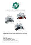
6. Connecting plan
DK 900/PDP
X1
4
8
X1
1
5
3
6
4
7
14
X3
Interface RS232
3 RTS
6 CTS
2 TXD
5 RXD
1 Shield
4 GND
X3
In / Outputs
7 IN 5:
6 IN 4:
5 IN 3:
4 IN 2:
3 IN 1:
2 IN 0: tare
1 +UB DIO 12-30V
8
1
X6
1
2
3
X5
Supply
1 +24V
2 GND
3 PE
4 PE
X6
Profibus
D-Sub 9pol.Bu
4
X5
Dimensions:
H = 99, W = 45, D = 115
without plugs
8 -Signal
7 -Sense
6 GND
5 Shield
X2
X2
1
Load cell
4 +Signal
3 +Sense
2 +10V
1 Shield
14 OUT 5:
13 OUT 4:
12 OUT 3:
11 OUT 2:
10 OUT 1:
9 OUT 0:
8 GND DIO
MESOMATIC
Automation u. Meßtechnik GmbH
71394 K E R N E N
Änderung
DK900
Tag
Name
Dec. 04
Schn
Tag Name
20
DK 900/PDP
connecting plan
MESOMATIC
Automation und Messtechnik GmbH
D-71394 Kernen
6 wire load cell electrical connection
DMS
X1-2
Supply +10V
X1-3
Sense +
X1-4
Signal +
X1-8
Signal -
X1-7
Sense -
X1-6
Supply 0V
X1-1
Shield
4 wire load cell electrical connection
DMS
X1-2
Supply +10V
X1-3
Sense +
X1-4
Signal +
X1-8
X1-7
X1-6
X1-1
Signal Sense Supply 0V
Shield
Special version: measurement potentiometer
X1-2
Supply +10V
X1-3
Sense +
X1-4
X1-8
Signal -
X1-7
Sense -
X1-6
Supply 0V
X1-1
DK900
Signal +
21
Shield
MESOMATIC
Automation und Messtechnik GmbH
D-71394 Kernen
7. Serial cable
shield
RxD
2
3
2
TxD
TxD
3
2
5
RxD
RTS
7
4
6
CTS
CTS
8
5
3
RTS
Gnd
5
7
4
Gnd
DCD
1
8
DTR
4
20
DSR
6
6
RI
9
22
PC
COM1/2
DK900
1
9 pol.
Min.D.
DK900 X2
25 pol.
Min.D.
22