1
SMVector RS-485 LECOM Communication Module
Communications Interface Reference Guide
About these instructions
This documentation applies to the RS-485 / LECOM communications option for the SMVector inverter and should be
used in conjunction with the SMVector Operating Instructions (Document SV01) that shipped with the drive. These
documents should be read in their entirety as they contain important technical data and describe the installation and
operation of the drive and this option.
WARNING!
The information in this document is based on RS-485 LECOM Communication Module software version 1.20. If a
future revision of software contains differences in the register numbering or register definitions, drive operation
could be seriously affected. If drive parameter P494 does not display 1.20, then writing to any drive register over
the network MUST NOT BE ATTEMPTED as it would have the potential for unexpected consequences potentially
resulting in damage to the equipment or harm to personnel. Future releases of module software require that the
appropriate documentation be used for implementation.
NOTE
To use the LECOM option of the RS-485 communication module with the SMVector (0.33-10HP) requires standard
software version 3.0 or later. All SMVector 15HP (11kW) and higher models support the LECOM option on the
RS-485 communication module.
© 2008 Lenze AC Tech Corporation
No part of this documentation may be copied or made available to third parties without the explicit written approval of
Lenze AC Tech Corporation.
All information given in this documentation has been carefully selected and tested for compliance with the hardware
and software described. Nevertheless, discrepancies cannot be ruled out. We do not accept any responsibility nor
liability for damages that may occur. Any necessary corrections will be implemented in subsequent editions.
Contents
1
Safety Information......................................................................................................................................................2
1.1
1.2
1.3
1.4
1.5
2
Introduction................................................................................................................................................................4
2.1
2.2
3
5.4
5.5
Configuration and Control Registers............................................................................................................................. 19
8.1.1
C1050 (Network Controlled Digital Output).................................................................................................. 22
8.1.2
C1055 (Network Controlled Analog Output)................................................................................................. 22
8.1.3
C1099 (Parameter Version)......................................................................................................................... 22
Programming Parameters.........................................................................................................................................23
9.1
9.2
9.3
9.4
10
Drive Monitoring.......................................................................................................................................................... 18
Drive Programming and Control................................................................................................................................... 18
Network Watchdog Timer............................................................................................................................................ 18
7.3.1
Watchdog Timer......................................................................................................................................... 18
7.3.2
Watchdog Time-out Period (P425).............................................................................................................. 18
7.3.3
Watchdog Time-out Action (P426)............................................................................................................... 18
Drive Registers.........................................................................................................................................................19
8.1
9
Telegram Response..................................................................................................................................................... 15
Receive Telegram........................................................................................................................................................ 15
Receive Telegram Response........................................................................................................................................ 15
Send Telegram............................................................................................................................................................ 16
Broadcast / Multicast................................................................................................................................................... 17
Commissioning.........................................................................................................................................................18
7.1
7.2
7.3
8
LECOM - A/B Protocol Description............................................................................................................................... 10
Controller address (AD1, AD2)..................................................................................................................................... 10
Code Number (C1, C2)................................................................................................................................................. 11
5.3.1
Standard Addressing.................................................................................................................................. 11
5.3.2
Addressing via Code Bank.......................................................................................................................... 11
5.3.3
Addressing via Input Selection.................................................................................................................... 12
5.3.4
Extended Addressing.................................................................................................................................. 12
Parameter Value (V1 to Vn).......................................................................................................................................... 12
Block-Check Character (BCC)...................................................................................................................................... 14
LECOM Message Details...........................................................................................................................................15
6.1
6.2
6.3
6.4
6.4
7
Drive Communication Parameters................................................................................................................................. 8
RS485 LECOM-Specific Parameters.............................................................................................................................. 9
LECOM Protocol Details............................................................................................................................................10
5.1
5.2
5.3
6
Mechanical Installation.................................................................................................................................................. 5
RS-485 Terminal Block................................................................................................................................................. 6
Electrical Installation..................................................................................................................................................... 6
3.3.1
Cable Types.................................................................................................................................................. 6
3.3.2
Network Limitations...................................................................................................................................... 6
3.3.3
Connections and Shielding............................................................................................................................ 6
3.3.4
Network Termination.................................................................................................................................... 7
Parameters for use with RS-485/LECOM.....................................................................................................................8
4.1
4.2
5
Module Specifications................................................................................................................................................... 4
Module Identification Label............................................................................................................................................ 4
Installation..................................................................................................................................................................5
3.1
3.2
3.3
4
General......................................................................................................................................................................... 2
Application.................................................................................................................................................................... 2
Installation..................................................................................................................................................................... 2
Electrical Connection..................................................................................................................................................... 2
Operation...................................................................................................................................................................... 3
Fault History (P500)..................................................................................................................................................... 23
Drive ID (P502)............................................................................................................................................................ 24
Terminal and Protection Status (P530)......................................................................................................................... 25
Keypad Status (P531).................................................................................................................................................. 25
Troubleshooting and Fault Elimination.......................................................................................................................26
10.1
10.2
Faults.......................................................................................................................................................................... 26
Troubleshooting.......................................................................................................................................................... 26
CMVLC401A
1
Safety Information
1
Safety Information
1.1
General
Some parts of Lenze controllers (frequency inverters, servo inverters, DC controllers) can be live, moving and rotating.
Some surfaces can be hot.
Non-authorized removal of the required cover, inappropriate use, and incorrect installation or operation creates the risk
of severe injury to personnel or damage to equipment.
All operations concerning transport, installation, and commissioning as well as maintenance must be carried out by
qualified, skilled personnel (IEC 364 and CENELEC HD 384 or DIN VDE 0100 and IEC report 664 or DIN VDE0110 and
national regulations for the prevention of accidents must be observed).
According to this basic safety information, qualified skilled personnel are persons who are familiar with the installation,
assembly, commissioning, and operation of the product and who have the qualifications necessary for their occupation.
1.2
Application
Drive controllers are components designed for installation in electrical systems or machinery. They are not to be used
as appliances. They are intended exclusively for professional and commercial purposes according to EN 61000-3-2.
The documentation includes information on compliance with EN 61000-3-2.
When installing the drive controllers in machines, commissioning (i.e. the starting of operation as directed) is prohibited
until it is proven that the machine complies with the regulations of the EC Directive 2006/42/EC (Machinery Directive);
EN 60204 must be observed.
Commissioning (i.e. starting drive as directed) is only allowed when there is compliance to the EMC Directive (2004/108/
EC).
The drive controllers meet the requirements of the Low Voltage Directive 2006/95/EC. The harmonised standards of the
series EN 50178/DIN VDE 0160 apply to the controllers.
The availability of controllers is restricted according to EN 61800-3. These products can cause radio interference
in residential areas. In the case of radio interference, special measures may be necessary for drive controllers.
1.3
Installation
Ensure proper handling and avoid excessive mechanical stress. Do not bend any components and do not change any
insulation distances during transport or handling. Do not touch any electronic components and contacts. Controllers
contain electrostatically sensitive components, which can easily be damaged by inappropriate handling. Do not damage
or destroy any electrical components since this might endanger your health! When installing the drive ensure optimal
airflow by observing all clearance distances in the drive's user manual. Do not expose the drive to excessive: vibration,
temperature, humidity, sunlight, dust, pollutants, corrosive chemicals or other hazardous environments.
1.4
Electrical Connection
When working on live drive controllers, applicable national regulations for the prevention of accidents (e.g. VBG 4) must
be observed.
The electrical installation must be carried out in accordance with the appropriate regulations (e.g. cable cross-sections,
fuses, PE connection). Additional information can be obtained from the regulatory documentation.
The regulatory documentation contains information about installation in compliance with EMC (shielding, grounding,
filters and cables). These notes must also be observed for CE-marked controllers. The manufacturer of the system or
machine is responsible for compliance with the required limit values demanded by EMC legislation.
2
CMVLC401A
Safety Information
1.5
Operation
Systems including controllers must be equipped with additional monitoring and protection devices according to the
corresponding standards (e.g. technical equipment, regulations for prevention of accidents, etc.). You are allowed to
adapt the controller to your application as described in the documentation.
DANGER!
• After the controller has been disconnected from the supply voltage, do not touch the live components
and power connection until the capacitors have discharged. Please observe the corresponding
notes on the controller.
• Do not continuously cycle input power to the controller more than once every three minutes.
• Close all protective covers and doors during operation.
WARNING!
Network control permits automatic starting and stopping of the inverter drive. The system design must
incorporate adequate protection to prevent personnel from accessing moving equipment while power
is applied to the drive system.
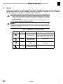
Table 1: Pictographs used in these instructions
Pictograph
Signal Word
Meaning
Consequences if Ignored
DANGER!
Warning of Hazardous
Electrical Voltage.
Reference to an imminent danger that may
result in death or serious personal injury if
the corresponding measures are not taken.
WARNING!
Impending or possible
danger for persons
Death or injury
STOP!
Possible damage to
equipment
Damage to drive system or its
surroundings
NOTE
Useful tip: If observed, it will
make using the drive easier
CMVLC401A
3
Introduction
2
Introduction
This reference guide assumes that the reader has a working knowledge of the LECOM Protocol and familiarity with the
programming and operation of motion control equipment. This guide is intended as a reference only.
2.1
Module Specifications
Table 2 identifies the LECOM serial communication specifications. If the specification is fixed (non-adjustable) the value
is shown under “Range”, if the specification is selectable, the table identifies the Parameter and available range of
selections.
Table 2: LECOM Serial Communication
Description
Type
Range
Network Address Selectable
P410 (1 - 99)
Baud Rate
Selectable
P411 (9600, 4800, 2400, 1200, 19200 bps)
Data Bits
Fixed
7
Parity / Stop Bits
Fixed
Even/1
Typical communications between master and slave would be:
• Write commands from Master
−− Run command
−− Frequency Reference
−− Modification of Drive operating parameters
• Requests from Master
−− Reporting of drive status
−− Fault status (and fault history)
2.2
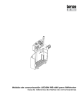
Module Identification Label
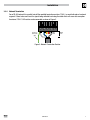
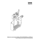
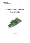
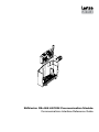
Figure 1 illustrates the labels on the SMV RS-485 communications module. The SMVector RS-485 module is identifiable by:
• Two labels affixed to either side of the module.
• The color coded identifier label in the center of the module.
Right-hand Label:
Ratings & Certifications
COMM I/O ONLY
S/N: 123456789
LISTED
Fieldbus Identifier:
R = RS-485 (Modbus RTU/LECOM)
R0
Left-hand Label:
Module Data
SMV RS-485
TYPE: ESVZAR0
ID-NO: 12345678
ESVZAR0-000XX1A10
A
B
C
D
E
A: Fieldbus Protocol
B: Model Number
C: Lenze Order Number
D: Firmware Revision
E: Hardware Revision
Figure 1: RS-485 Module Labels
4
CMVLC401A
Installation
3
Installation
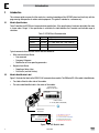
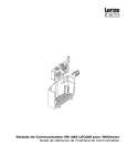
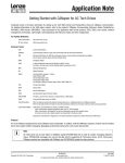
3.1
Mechanical Installation
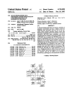
1. Ensure that for safety reasons the AC supply has been disconnected before opening the terminal cover.
2. Insert the RS-485 option module in the terminal cover and securely “click” into position as illustrated in Figure 2.
3. Wire the network cables to the connector provided, as detailed in paragraphs 3.2 (RS-485 Terminal Block) and 3.3
(Electrical Installation), and plug the connector into the option module.
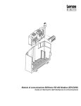
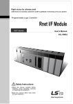
4. Align terminal cover for re-fitting, connect the module umbilical cord to the drive then close the cover and secure,
as shown in Figure 3.
1 2 3 4 5
0.5 Nm/ 4.5 lb-in
<
_ 2.8 mm2
(12-22 AWG)
7mm
NEMA 1 (IP31) Models
NEMA 4X (IP65) Models
Figure 2: Installing the RS-485 Communications Module
NEMA 1 (IP31) Models
NEMA 4X (IP65) Models
Figure 3: Re-installing the Terminal Cover
CMVLC401A
5
Installation
3.2
RS-485 Terminal Block
For a LECOM network, wire the RS-485 connector as detailed in Table 3.
Table 3: RS-485 Pin Designation
Terminal Description
Important
1
Earth ground / shield For reliable communication make sure terminal is
connected to the LECOM network GND/common. If
only two wires are used (TXA and TXB) in the network,
connect Terminal 1 to chassis/earth ground.
2
TXA
If controller is located at either end of the network,
a terminating resistor (120ohm typical) should be
3
No connection
connected across TXA and TXB
4
TXB
5
RS-485 Connector
1
4
23
5
No connection
Protection against contact
• All terminals have basic isolation (single insulating distance)
• Protection against contact can only be ensured by additional measures (i.e. double insulation)
3.3
Electrical Installation
3.3.1 Cable Types
For RS-485 LECOM-B networks, use a quality shielded twisted pair cable. The use of low quality cable will result in
excess signal attenuation and data loss.
3.3.2 Network Limitations
There are several limiting factors that must be taken into consideration when building an RS-485 LECOM network:
• LECOM-B networks are limited to: 31 devices (w/o repeaters); 90 w/ repeaters).
• Topology: Without repeaters: line; with repeaters: line or tree.
• Maximum total network length is 1200 m depending on the baud rate and cable used.
• Minimum of 1 meter of cable between nodes.
3.3.3 Connections and Shielding
To ensure good system noise immunity all networks cables should be correctly grounded:
• Minimum grounding recommendation: ground the network cable once in every cubical.
• Ideal grounding recommendation: ground the network cable on or as near to each drive as possible.
• For wiring of cable to the connector plug the unscreened cable cores should be kept as short as possible;
recommended maximum of 20mm. The shield connection of terminal 1 should also be wired to earth (PE).
1
2
3
Connect to
drive earth
(PE)
4
5
20mm
max
Figure 4: Connector Wiring Diagram
6
CMVLC401A
Installation
3.3.4 Network Termination
For an RS-485 network it is essential to install the specified termination resistors (120W), i.e. one at both ends of a network
segment. Failure to do so will result in signals being reflected back along the cable which will cause data corruption.
An external 120W 1/4W resistor can be connected as shown in Figure 5.
1
2
3
Connect to
drive earth
(PE)
4
5
120Ω
1/4W
20mm
max
Figure 5: Network Termination Resistor
CMVLC401A
7
Commissioning
4
Parameters for use with RS-485/LECOM
4.1
Drive Communication Parameters
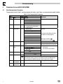
The parameters listed in Table 5 are always present on the drive, even if there is no communication module installed.
Table 5: Drive Communication Parameters
Code
No.
P400
P401
P402
P403
Module Reset
0
P404
Module Time-out
Action
3
P405
Network Fault
0
P406
Proprietary
P498
Missed Messages
Drive to Module
Missed Messages
Module to Drive
P499
8
Possible Settings
Name
Default Selection
Network Protocol
0 Not Active
1 Remote Keypad
2 Modbus RTU
7 LECOM-B
Module Revision 01.0.0 Display reads 01.x.x where:
01 = RS485/Remote Keypad Module
x.x = Module Revision
Module Status
0
0 Not Initialized
1 Initialization: Module to EPM
2 Initialization: EPM to Module
3 Online
IMPORTANT
Read only
Read only
the communications between the drive
and module are working properly.
4 Failed Initialization Error
5 Time-out Error
6 Initialization Failed
Module type mismatch ( 0 )
7 Initialization Error
Protocol Selection mismatch ( 0 )
0 No Action
Returns module parameters 401…499 to
1 Reset Module parameter values to
default.
the default values shown in this manual.
0 Ignore
• Action to be taken in the event of an
SPI Time-out.
1 STOP (refer to 11 )
•
SPI Time-out is fixed at 200ms.
2 Quick Stop
3 Fault ( n )
0 No Fault
Read only, see P425 and P426
1 Network Time-out, F
Module specific
Read only
NOTE:
If this parameter returns a value of 16, the software version in this SMVector drive
does not support the LECOM functionality. Contact factory technical support.
Read only
Read only
CMVLC401A
Commissioning
4.2
RS485 LECOM-Specific Parameters
The parameters listed in Table 6 are only present in the drive if there is an RS485 communication module installed,
P400 = 7 and the module is online (P402 = 3).
Table 6: RS485 LECOM-Specific Parameters
Code
No.
P410
Name
Network address
Possible Settings
Default Selection
1
1
P411
Network
Baud Rate
0
P420
Network Control
Level
0
P424
Network Powerup
Start Status
0
P425
Network Message
time-out
Network Message
time-out action
50
P427
Valid Network
messages
Received
0
P494
Communication
Module software
version
Internal Code
P426
P495
0
IMPORTANT
99
0
1
2
3
4
0
1
2
3
4
9600 bps
4800 bps
2400 bps
1200 bps
19200 bps
Monitor Only
Parameter Programming
Programming and Setpoint Control
Full Control
Full Control (Special)
0
1
0
Quick Stop
Controller Inhibit
{ms}
0
1
2
3
0
No action
Controller Inhibit
Quick Stop
Trip Fault, F.nF1
{messages} 9999
CMVLC401A
The values 00, 10, 20, 30 … 90 must not
be used since they are reserved for group
addressing (see section 6.4).
P420 =2, 3: setpoint control using code
number C0046 or C1061.
P420 = 3, 4: drive control using code
numbers C0040 and/or C0135
P420 = 4: setting C0140 = 0 results in
Quick Stop
Stop commands (QUICK STOP, INHIBIT)
will always be accepted.
65000
•
•
•
•
Read-only
When number of messages exceed
9999, counter resets and resumes
counting from 0.
Read only
Format: x.yz
•
•
Read only
Alternating Display: xxx-; -yy
9
Commissioning
5
LECOM Protocol Details
5.1
LECOM - A/B Protocol Description
The LECOM-A/B protocol is used to exchange data between SMV controllers and a host. The LECOM-A/B protocol is
based on DIN 66019, ISO 1745 and ANSI X3.28 (category 2.5 and A2, A4). These standards are similar to each other
and describe the control mode of a transmission section of a transmission system.
The host (the master) can communicate with a slave (SMV controller) in three modes:
• RECEIVE (refer to 6.2)
• SEND (refer to 6.3)
• BROADCAST/MULTICAST (refer to 6.4)
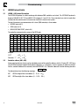
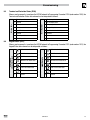
The controllers communicate by means of the ASCII code:
0
1
NUL SOH
DLE DC1
space !
0
1
@
A
P
Q
‘
a
p
q
0
1
2
3
4
5
6
7
2
STX
DC2
“
2
B
R
b
r
3
ETX
DC3
#
3
C
S
c
s
4
EOT
DC4
$
4
D
T
d
t
5
ENQ
NAK
%
5
E
U
e
u
6
ACK
SYN
&
6
F
V
f
v
7
BEL
ETB
‘
7
G
W
g
w
8
BS
CAN
(
8
H
X
h
x
9
TAB
EM
)
9
I
Y
i
y
0
LF
SUB
*
:
J
Z
j
z
B
VT
ESC
+
;
K
[
k
{
C
FF
FS
,
<
L
\
I
I
D
CR
GS
M
]
m
}
I
SO
RS
.
>
N
^
n
~
F
SI
US
/
?
O
_
o
DEL
Example:
“EOT”
= 02hex = 2dec
Character “ 1” = 31hex = 49dec
5.2
Controller address (AD1, AD2)
One or more bus devices (slaves) can be selected by means of the controller address, which is 2 bytes (AD1, AD2) long.
The LECOM-A/B protocol supports the broadcast telegrams, i.e. a telegram is sent to a group or all other bus devices.
For this, controller addresses are reserved (refer to BROADCAST, 6.4). Controller addresses have the following structure:
AD1
AD2
The abbreviations have the following meanings:
10
AD1
ASCII ten-digit of the slave address (0 ... 9; 30 ... 39hex)
AD2
ASCII one-digit of the slave address (0 ... 9; 30 ... 39hex)
CMVLC401A
Commissioning
5.3
Code Number (C1, C2)
5.3.1 Standard Addressing
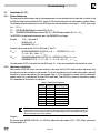
The meaning of the code numbers and the assigned parameters can be obtained from the code table (in section 9) and
the SMV Operating Instructions Manual (SV01, section10). When transmitting data, the code number is coded as follows:
The following calculation determines the two ASCII digits from the code number (value range: 0 ... 6229) (value range:
48 dec ...127dec):
C1 = INTEGER((REMAINDER(code number/790)Y10)+48 dec
C2 = REMAINDER(REMAINDER(code number/790)/10) + INTEGER(code number/790) x 10 + 48 dec
The INTEGER is the digit before the decimal point, the REMAINDER is an integer.
Example:
13/5 = 2 remainder 3
INTEGER(13/5) = 2
REMAINDER(13/5) = 3
Example: Convert code number 1002 in ASCII code C1 and C2:
C1ASCII =
INTEGER((REMAINDER(1002/790/10) + 48 =
21 + 48 = 69 = 45hex = “E” ASCII
C2ASCII =
REMAINDER(REMAINDER(1002/790)/10) + INTEGER(1002/790) x 10 + 48 =
REMAINDER(212/10) + 1 x 10 + 48 = 2 + 10 + 48 = 60 = 3C hex = “<” ASCII
INTEGER(212/10) + 48 =
The code number C1002 is converted into the ASCII string “E<”, if they are transmitted to the controller by a host.
5.3.2 Addressing via Code Bank
With previous LECOM-A/B drivers, only code numbers in the range from 0 to 255 could have been addressed, since
these drivers used only one byte as code number. To achieve the addressing of the wider code-number range with
these drivers, use the code banking. The code-number range 0...255 is displayed as a window over the whole codenumber range. This is controlled via the code C0249 (code bank). Code C0249 can always be accessed via number
249, independent of the currently set code bank.
Table 7: Code Bank Assignment
Code bank Code offset
0
1
2
3
4
5
6
7
0
250
500
750
1000
1250
1500
1750
Code-number range
0 - 255
250 - 505
500 - 755
750 - 1005
1000 - 1255
1250 - 1505
1500 - 1755
1750 - 2005
NOTE
Code banking is only active when the standard addressing is being used. If the selected code numbers are
higher than 255, the code-number range increases correspondingly. Only the corresponding code-number
offset is selected by means of the code bank.
Example:
Set the code bank INTEGER(1002/250) =4 in C0249 to address the code number 1002. C1002 is then accessed via
the code number C02.
CMVLC401A
11
Commissioning
5.3.3 Addressing via Input Selection
Simple LECOM-A/B drivers, which only use the standard addressing, cannot address subcodes. The input selection
C0248 has been developed to offer the possibility of addressing the subcodes. When using the standard addressing,
the value entered in C0248 is always considered as the subcode. The code C0248 can always be accessed via number
248, independent of the currently set code bank and the sub code used.
Example:
Enter value 1 in C0248 to address the JOG value 1 in subcode 1. Now subelement 1 is always addressed when accessing
C39.
NOTE
After a sub element has been accessed through C0248, C0248 should be reset to 0 to avoid the addressing
of a subelement “by accident” when accessing another code.
5.3.4 Extended Addressing
Another possibility is the direct addressing of parameters by means of expanded addressing.
!
CH1
CH2
CH3
CH4
SC1
SC2
The abbreviations have the following meanings:
!
The ASCII character “!” = 21hex = 33dec shows that the expanded addressing is used
CH1 to CH4
Code number in hexadecimal code: each character corresponds to a nibble of the code numbers (CH1
is the highest, CH4 is the lowest nibble).
SC1, SC2
Subcode number in hexadecimal code: each character corresponds to a nibble of the code number
word (SC1 is the highestand SC2 the lowest nibble).
The following characters can be displayed in the ASCII code:
ASCII
Dec
Hex
0
48
30
1
49
31
2
50
32
3
51
33
4
52
34
5
53
35
6
54
36
7
55
37
8
56
38
9
57
39
A
65
41
B
66
42
C
67
43
D
68
44
E
69
45
F
70
46
A code number range from 0 to 65535 can be addressed by means of these characters. A maximum of 255 subelements
(field elements) can be accessed via one subcode number of each code. Example: 1002 = “!03EA00”
5.4
Parameter Value (V1 to Vn)
Parameter values can be transmitted in four different formats with the following structures:
• ASCII decimal format (VD)
-
VK1
VK2
VK3
VK4
VK5
VK6
.
NK1
VH3
VH4
VH5
VH6
VH7
VH8
VS3
VS4
VS5
VS6
...
VS240
VO6
...
VO240
• ASCII hexadecimal format (VH)
H
VH1
VH2
• String format (VS)
S
VS1
VS2
• Octet string format for data blocks (VO)
O
12
VO1
VO2
VO3
VO4
VO5
CMVLC401A
NK2
NK3
NK4
Commissioning
The abbreviations have the following meanings:
VK1 to VK6
Integers
.
Decimal point (if required)
NK1 to NK4
Decimal codes (if required)
“H” (48hex)
Character [H], transfer of parameter values in the ASCII hexadecimal format
VH1 to VH8
1 to 8 hexadecimal characters each [0 to 9; A to F]
“S” (53hex)
Character [S], transfer of parameter values in the string format
VS1 to VS240 1 to 12 visible ASCII characters each (no control characters)
“O” (4Fhex)
Character [0], transfer of parameter values in the octet string format
VO1 to VO240 Data block in hexadecimal code; each character corresponds to a nibble of the data block
Parameter value in the ASCII decimal format (110)
The ASCII decimal format (VD) is most often used. The values consist of the following:
1 leading negative sign (if required)
6 digits before the decimal point (VK1 to VK6)
1 decimal point (if required)
4 digits after the decimal point (NK1 to NK4) (if required)
Values from -214748.3648 to 214748.3647 can be displayed.
NOTE
In the ASCII decimal format (VD), the decimal point must not be transmitted if the value does not have digits
after the decimal point.
Parameter value in ASCII hexadecimal format (VH)
The LECOM-A/B protocol supports the transmission of hexadecimal parameter values with a length of:
• 2 characters (byte value)
• 4 characters (word/integer value)
• 8 characters (double word/long integer)
In the ASCII hexadecimal format, VH1 is the most significant and VH8 the least significant hexadecimal character.
Parameter value in the string format (VS)
By means of the string format (VS) of the protocol it is possible to transmit strings with a maximum of 20 characters in
both directions.
The SMV inverter can only send the string parameters (e. g. C200).
CMVLC401A
13
Commissioning
Parameter values in the octet string format (VO)
The LECOM-A/B protocol includes the octet string format (VO) with which it is possible to transfer data blocks.
The character sequence corresponds to the filing in the memory (ascending order), i.e. the character transmitted first
is the data block nibble with the lowest address. The data structure of the data block corresponds to the Intel-memory
format with the following definition:
5.5
BYTE:
1st high nibble
2nd low nibble
WORD:
1st high BYTE
2nd low BYTE
DWORD:
1st high WORD
2nd low WORD
Block-Check Character (BCC)
The block-check character (BCC) is used to store the transmitted data and is generated according to DIN 66219 (chapter 3).
Because of the program, the block-check character is generated by an XOR link from the following digits of the SEND
telegram:
• it starts with the character directly after the STX control character
• it ends directly after the ETX control character
- BCC can accept the value 00 ... FFhex.
EOT
AD1
AD2
STX
C1
C2
V1
O
Vn
ETX
BCC
or with expanded addressing:
STX
“!”
CH1
CH2
O
SC2
ETX
BCC
14
CMVLC401A
BCC
BCC
Commissioning
6
LECOM Message Details
6.1
Telegram Response
The SMV controller must return an acknowledgement to the host. The only exceptions to this are when a broadcast
telegram is received or when the controller address is not correct. These telegrams do not require an acknowledgement.
The SMV controller sends two types of acknowledgements:
• Negative acknowledgement (NAK = 15hex), if:
−− a fault (e.g. parity fault) was detected in one or more characters, including the character ENQ
−− an invalid command or variable address has been recognized
−− the variable value is not within the permissible range
• Otherwise, Positive acknowledgement (ACK = 06hex)
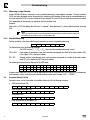
6.2
Receive Telegram
The command RECEIVE is to request parameter values of the SMV controllers. The code numbers of the requested
parameter are transmitted via the RECEIVE telegram using the following structure:
EOT
AD1
AD2
C1
C2
ENQ
The abbreviations have the following meanings:
EOT (04hex)
End of the (previous) transmission
AD1, AD2
Logic unit address of the slave to be addressed Slaves
C1, C2 Code number (two ASCII characters) or extended addressing
ENQ (05hex)
6.3
Station request
Receive Telegram Response
The SMV controller addressed via a RECEIVE telegram generates one of the following responses:
• The controller could decode the request and is now sending the requested parameter value to the host.
STX
C1
C2
V1
O
Vn
ETX
BCC
• The controller could decode the request, however, a check-sum fault (parity fault) occurred during transmission.
STX
C1
C2
?
ETX
BCC
• The controller could not process the request because the requested code number does not exist.
STX
C1
C2
EOT
The abbreviations have the following meanings:
STX (02hex)
Start of text
C1, C2
Code number (two ASCII characters) or extended addressing
V1 to Vn
Parameter value (n ASCII characters)
ETX (03hex)
End of text
BCC
Block-check character (00 ... FFhex)
? (3Fhex)
ASCII character “?”
EOT (04hex)
End of the (previous) transmission
Structure and meaning of the block-check character (BCC) are described in the corresponding paragraph of the chapter
SEND.
CMVLC401A
15
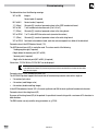
Commissioning
Example 1
The current speed setpoint (code number C46) is to be read with the bus address 01 at the controller. The host sends
the following RECEIVE telegram
EOT
0
1
4
6
ENQ
The controller can respond in three different ways:
STX
4
6
3
5
.
4
ETX
BCC
Valid request: The current value of the parameter C46 is 35.4 (Hz) or
STX
4
6
?
ETX
BCC
Invalid request: A check-sum fault (parity fault) occurred during data transmission or
STX
4
6
EOT
Invalid request: Parameter C46 does not exist in this controller.
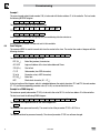
6.4
Send Telegram
The command SEND is used to transmit data from the master to the slave. The master then sends a telegram with the
following structure:
EOT
AD1
AD2
STX
C1
C2
V1
O
Vn
ETX
BCC
The abbreviations have the following meanings:
EOT (04hex)
End of the (previous) transmission
AD1, AD2
Logic unit address of the slave to be addressed Slaves
STX (02hex)
Start of text
C1, C2
Code number (two ASCII characters)
V1 to Vn
Parameter value (n ASCII characters)
ETX (03hex)
End of text
BCC
Block-check character (00 ... FFhex)
In the text section of the telegram, which is embedded between the control characters STX and ETX, the code number
(C1. C2) and the corresponding parameter value (V1 to Vn) are transmitted to the slave.
Example for a SEND telegram:
The maximum speed (code number C1103) is to be set to the value 95.2 Hz via the bus address 34 at the controller.
The host must send the following SEND telegram:
EOT
3
4
STX
0
1
9
5
.
2
ETX
BCC
The controller can respond with one of two acknowledgements:
ACK
The command was processed correctly. The current value of the parameter C1103 is 95.2 Hz or
NAK
The request could not be processed correctly. The value of parameter C1103 has not been changed.
16
CMVLC401A
Commissioning
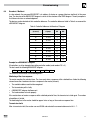
6.4
Broadcast / Multicast
In a bus network, the command BROADCAST is to address all devices or a group of devices (multicast) at the same
time. The structure of the BROADCAST telegram is similar to the structure of the SEND telegram. The only exception is
that it does not return an acknowledgement.
The devices can be selected via their controller addresses. The controller addresses listed in Table 8 are reserved for
a BROADCAST telegram.
Table 8: Controller Addresses for Broadcast Telegram
Controller address
(reserved)
Controller address
of groups
00
ASCII character
AD1
AD2
all
“0”
“0”
10
11 to 19
“1”
“0”
20
21 to 29
“2”
“0”
30
31 to 39
“3”
“0”
40
41 to 49
“4”
“0”
50
51 to 59
“5”
“0”
60
61 to 69
“6”
“0”
70
71 to 79
“7”
“0”
80
81 to 89
“8”
“0”
90
91 to 99
“9”
“0”
Example for a BROADCAST telegram:
All controllers are to be stopped when setting controller enable (code number C40 = 0).
The host sends the following BROADCAST telegram:
EOT
0
0
STX
4
0
0
ETX
BCC
The controllers do not return an acknowledgement.
Monitoring of the slave response:
The master monitors the selected slave. The slave must return a response within a defined time. Under the following
circumstances the slave does not return a response to the master (time out):
• The controller address could not be recognized
• The transmission path is faulty
• A BROADCAST telegram had been sent.
• The hardware does not work properly
If the master does not receive a response within a defined period of time, the transmission is tried again. The number
of repetitions is limited.
The monitoring time in the master should be approx. twice as long as the maximum response time.
Transmission faults
After a transmission fault, the master can read C0068 and evaluate the communication error in bit 4... 7.
CMVLC401A
17
Commissioning
7
Commissioning
7.1
Drive Monitoring
The network can always read drive parameters as long as the LECOM communications are enabled (i.e. P400 = 7) and
configured properly (see P410-411). For monitor only operation, set P420 = 0.
7.2
Drive Programming and Control
Network Control must be enabled for the network to program drive parameters or take control of a drive. This is done by:
1. Setting P121…P124 equal to 09 (NET ENABLE) and asserting the corresponding TB-13x terminal
2. Setting P100 to 00, 01, 03, 04 or 06. Network control cannot be enabled when P100 is set to 02 (REMOTE KEYPAD
ONLY) or 05 (TERMINAL STRIP/REMOTE KEYPAD).
3. Setting P420 to 01, 02 or 03.
7.3
Network Watchdog Timer
7.3.1 Watchdog Timer
The SMV is equipped with a Serial Link “Watchdog Timer”. If the Watchdog Timer is enabled, the Master MUST
PERIODICALLY COMMUNICATE with the drive or the timer will timeout.
Watchdog timer setup is performed by using parameters P425 and P426 (LECOM codes C1425 and C1426).
7.3.2 Watchdog Time-out Period (P425)
The maximum amount of time that should be allowed to pass between network messages to a specific drive will vary from
one network to the next. Therefore, we have made the watchdog time-out period user settable via Drive Programming
Parameter P425 (refer to section 4.2 for details).
NOTE
To prevent erroneous timeout trips, make sure the time set in parameter P425 (C1425) is appropriate for
particular network - default value of 50ms might be to restrictive!
7.3.3 Watchdog Time-out Action (P426)
The appropriate action to be taken when a watchdog time-out occurs will also vary from one application to the next.
Therefore, we have provided four user selectable time-out actions which can be set via Drive Programming Parameter
P426.
The selections are:
0)
No action
Watchdog timer is disabled.
1)
Controller inhibit If the drive doesn’t receive valid communication for period longer than the time specified in
parameter P425 (C1425), it will coast to stop and drive display will show inhibit state ‘Stop’.
2)
Quick Stop
3)
Trip fault ‘F.nF1’ If the drive doesn’t receive valid communication for period longer than the time specified in
parameter P425 (C1425), it trips with fault ‘F.nF1’.
If the drive doesn’t receive valid communication for period longer than the time specified in
parameter P425 (C1425), it will ramp to stop and drive display will show stop state ‘Stop’.
WARNING!
Disabling the watchdog timer may cause injury to personnel and/or damage to equipment. The watchdog
timer should only be disabled during configuration or diagnosis to prevent nuisance timeout trips.
18
CMVLC401A
Commissioning
8
Drive Registers
8.1
Configuration and Control Registers
Registers #1 through #1099 are reserved for registers that are only available over the network and cannot be accessed
via the drive’s local keypad.
Table 9: Configuration & Control Registers
Code
Parameter Name
Number
Default Range of Adjustment
Important
C0040
Controller Inhibit
0
0
1
Controller inhibited
Controller enabled
The controller can also be enabled
with the control word C0135
C0043
Fault Reset
0
0
1
No Action
Reset Fault
The fault can also be reset with
the control word C0135
C0046
Frequency Setpoint
0.0
…
500.0 Hz
Read only
C0050
Actual Output
Frequency
0.0
…
500.0 Hz
Read only
C0068
Operating Status Bit
Word
Bit
Description
0-3
The 10th digit of the LECOM fault number is
displayed. Example:
TRIP OH = 5 (LECOM no. = 50)
4-7
Last communication error
0 = No fault
1 = Check sum error
2 = Protocol frame error
3 = Reserved
4 = Invalid code number
5 = Invalid variable
6 = No access permission
7 = Telegram processing interrupted by a new
telegram
15 = General fault
8
Control via LECOM enabled
9
Actual frequency above threshold C17
10
Direction of rotation
0 = CW
1 = CCW
11
Power stage transistors energized
12
Quick STOP active
13
Current Limit
14
Setpoint frequency reached
15
Fault occurred
Read only
LECOM Format = VH
CMVLC401A
19
Commissioning
Code
Parameter Name
Number
C0135
Controller Control
Word
Default Range of Adjustment
Bit
Description
0-1
JOG1, JOG2, JOG3
0 = C0046 active
1 = JOG1 (C0037) active
2 = JOG2 (C0038) active
3 = JOG3 (C0039) active
2
Rotation command
0 = CW
1 = CCW
3
Quick Stop
0 = QSP not active
1 = QSP active
4-8
Reserved
9
Controller inhibit
0 = No controller inhibit
1 = Controller inhibit
10
Reserved
11
Trip fault reset
0 -> 1
Edge from 0 to 1 causes TRIP reset
12-13 Reserved
14
DC Brake (DC injection brake)
0 = DCB not active
1 = DCB active
15
Reserved
LECOM Format = VH
C0140
20
Frequency Setpoint
Command
0.0 Hz 0.0 … 500.0 Hz
CMVLC401A
Important
Commissioning
Code
Parameter Name
Number
C0150
Controller Status
Word
Default Range of Adjustment
Bit
Description
0
Reserved
1
Power stage transistors energized
2
Current Limit reached
3
Reserved
4
Setpoint Frequency reached
5
Actual frequency above threshold C17
6
Actual frequency == 0Hz
7
Controller inhibit
0 = No controller inhibit
1 = Controller inhibit
Important
Read only
8 - 11 Controller status
0 = No error
1 = Error
12
Overtemperature fault
13
DC Bus overvoltage
14
Direction of rotation
0 = CW
1 = CCW
15
Read for operation
0 = fault (not ready for operation)
1 = no fault (ready for operation)
LECOM Format = VH
CMVLC401A
21
Commissioning
Code
Parameter Name
Number
Default Range of Adjustment
Important
C0200
Software
Identification
Software identification string:
example “33SSSMD-M_14000”
LECOM Format = VS
Read only
C0201
Software
Generation Date
Software generation date:
example “2008-10-18”
LECOM Format = VS
Read only
C1050
Network Controlled
Digital Output
(TB14) + Relay
0 = de-energized
1 = energized
bit 9: TB-14 state
bit 10: Relay state
other bits are not used
Refer to section 8.1.1
C1055
Network Controlled
Analog Output
0.0
Refer to section 8.1.2
C1060
Keypad Speed
Command
C1061
Network Speed
Command
C1070
Keypad PID
Setpoint Command
0.0
C1071
Network PID
Setpoint Command
C1072
0.0%
…
100.0
20.0 Hz P102
…
P103
0.0 Hz P102
…
P103
-99.9
…
3100.0
Read only
0.0
-99.9
…
3100.0
Read-only
Actual PID setpoint
0.0
-99.9
…
3100.0
Read only
C1073
PID Setpoint
Command
0.0
-99.9
…
3100.0
Read only
C1074
PID Feedback
0.0
-99.9
…
3100.0
Read only
C1080
Keypad Torque
Command
100%
0.0
…
400.0
C1081
Network Torque
Command
0%
0.0
…
400.0
C1099
Parameter Version
Refer to section 8.1.3
8.1.1 C1050 (Network Controlled Digital Output)
To control the state of the relay or digital output (TB14), Drive Programming Parameter P140 and/or P142 must be set
to 25 (Network Controlled).
8.1.2 C1055 (Network Controlled Analog Output)
To control the state of the analog output (TB30), Drive Programming Parameter P150 must be set to 09 (Network
Controlled).
8.1.3 C1099 (Parameter Version)
The Parameter Version identifies the parameter set for the current version of software. If the Parameter version is
different between two drives, it could indicate that a register has been added or deleted, a register’s min/max limits
have changed, a register’s function has been changed, or a register’s default value has been changed.
22
CMVLC401A
Commissioning
9
Programming Parameters
There is an offset of 1000 between the Drive Programming Parameter numbers and the code numbers used in the
LECOM messages. For example, if you want to read Drive Programming Parameter P103 (Maximum Frequency) over
the LECOM network, you would read code number 1103.
9.1
Fault History (P500)
Value
0
1
2
3
4
5
6
7
8
9
10
11
12
13
14
15
16
17
18
19
20
21
22
23
24
25
26
27
28
29
30
31
32
33
34
35
36
Display
F.OF
F.OF1
F.AF
F.rF
F.HF
F.LF
F.PF
F.GF
F.IL
F.dbF
F.SF
F.EF
F.CF
F.UF
F.cF
F.F1
F.F2
F.F3
F.F5
F.F5
F.F6
F.F7
F.F8
F.F9
F.bF
F.F12
F.JF
F.AL
F.F4
F.F0
F.FoL
F.F11
F.ntF
F.Fnr
F.nF1
Fault Message
No Fault
TMP Output Fault
Output (Transistor) Fault
Ground Fault
High Drive Temperature
Flying Start Fault
High DC Bus Voltage
Low DC Bus Voltage
Motor Thermal Overload
OEM Fault
Illegal Setup
Dynamic Brake Over Temperature
Single Phase Fault
External Fault
Control Fault
Start Error (Power loss)
Incompatibility Fault
Internal Fault 1 (EPM)
Internal Fault 2
Internal Fault 3
Internal Fault 5 (stack overflow)
Internal Fault 5 (stack underflow)
Internal Fault 6
Internal Fault 7
Internal Fault 8
Internal Fault 9
Personality Fault
Internal Fault (AD Offset)
Internal Fault (Remote Keypad Lost)
Assertion Level switched during Operation Fault
Internal Fault 4 (FGD Missing)
Internal Fault 0 (PW Missing)
Follower Lost
ISO Comm Fault
Internal Fault (Module Communication (SPI) Timeout)
Internal Fault (FNR: Invalid Message Received)
Network Time-out
CMVLC401A
23
Commissioning
9.2
Drive ID (P502)
This register returns an index value that is associated with the voltage and power rating of the drive. Table 10 lists the
drive configuration by Index number.
Table 10: Drive ID
Index
Input Voltage
Power Rating
8
240 VAC, Single-Phase
0.33 HP (0.25 kW)
12
13
14
240 VAC
Single or Three-Phase
2 HP (1.5 kW)
3 HP (2.2 kW)
21
0.5 HP (0.37 kW)
23
1 HP (0.75 kW)
24
1.5 HP (1.1 kW)
25
2 HP (1.5 kW)
26
28
240 VAC
Three-Phase
3 HP (2.2 kW)
5 HP (4 kW)
29
7.5 HP (5.5 kW)
30
10 HP (7.5 kW)
31
15 HP (11 kW)
32
20 HP (15 kW)
42
0.5 HP (0.37 kW)
44
1 HP (0.75 kW)
45
1.5 HP (1.1 kW)
46
2 HP (1.5 kW)
47
3 HP (2.2 kW)
49
50
480 VAC
Three-Phase
5 HP (4 kW)
7.5 HP (5.5 kW)
51
10 HP (7.5 kW)
52
15 HP (11 kW)
53
20 HP (15 kW)
54
25 HP (18.5 kW)
55
30 HP (22 kW)
69
1 HP (0.75 kW)
71
2 HP (1.5 kW)
72
3 HP (2.2 kW)
74
5 HP (4 kW)
75
76
600 VAC
Three-Phase
7.5 HP (5.5 kW)
10 HP (7.5 kW)
77
15 HP (11 kW)
78
20 HP (15 kW)
79
25 HP (18.5 kW)
80
30 HP (22 kW)
91
0.33 HP (0.25 kW)
92
94
120 or 240 VAC
Single-Phase
All unused Index values are reserved for future use
24
1.5 HP (1.1 kW)
CMVLC401A
0.5 HP (0.37 kW)
1 HP (0.75 kW)
Commissioning
9.3
Terminal and Protection Status (P530)
TB-13D Input Status
8
TB-13C Input Status
1
reserved
9
TB-14 Output Status
2
Protection Status
10 Relay Output Status
3
Fast Current Limit Status
4
Input TB-1 Status
5
reserved
6
TB-13A Input Status
14 reserved
7
TB-13B Input Status
15 reserved
11 Charge Relay State
12 Assertion Level Switch State
13 reserved
Keypad Status (P531)
When a read command is issued over the LECOM network to Programming Parameter P531 (code number 1531), the
Keypad Status data returned can be interpreted as follows:
0
UP Push-button State
8
UP Push-button State
1
DOWN Push-button State
9
DOWN Push-button State
2
MODE Push-button State
10
MODE Push-button State
3
FWD/REV Push-button State
11
FWD/REV Push-button State
4
STOP Push-button State
STOP
START Push-button State
5
Data High Byte
REMOTE Keypad
Data Low Byte
LOCAL Drive Keypad
9.4
0
Data High Byte
Data Low Byte
When a read command is issued over the LECOM network to Programming Parameter P530 (code number 1530), the
Terminal and Protection Status data returned can be interpreted as follows:
12
13
RUN
6
7
CTRL
STOP Push-button State
STOP
START Push-button State
RUN
CTRL Push-button
14
Unused
15
CTRL
CMVLC401A
CTRL Push-button
Unused
25
Troubleshooting and Fault Elimination
10
Troubleshooting and Fault Elimination
10.1
Faults
Table 11 lists the faults common to the LECOM communications module.
Table 11: Faults
Fault Code Fault
F
10.2
Cause
Remedy
f
Module to Drive
communication time out
Connection between drive and Check cable and connection
module is not made.
between module and drive
1
Network Time-out Fault
Drive under NETWORK control
and network communications
have been lost.
See parameters P425, P426
Troubleshooting
Table 12 lists some common LECOM communications problems and possible corrective action.
Table 12: Troubleshooting
Symptom
Possible Cause
Remedy
No communication
from the drive
Module is not initialized properly
•
•
Verify the module connection
Check P400 and P402
Incorrect LECOM settings
•
•
Use P403 to reset LECOM parameters.
Verify P410 and P411
Improper wiring
•
Check wiring between the LECOM Network and
communication module.
Ensure that terminal block is properly seated.
Check connection between module and drive.
•
•
26
LECOM write
commands are
ignored or return
exceptions.
“Network Enabled” terminal is either
open or not configured.
Drive stops without
obvious reason
LECOM message monitoring time-out
occurred. The timeout reaction is set to
Quick stop or Inhibit.
Configure one of the input terminals (P121 ... P124)
to “Network Enabled” function (selection 9) and close
the corresponding contact.
Network Control Level set to monitor only Set P420 = 1, 2, 3 or 4
(P420 = 0)
CMVLC401A
Modify the setting of time-out time (P425) or the
reaction to the time-out (P426).
Lenze AC Tech Corporation
630 Douglas Street • Uxbridge, MA 01569 • USA
Sales: (508) 278-9100 • Service (508) 217-9100
www.lenzeamericas.com
Document
CMVLC401A-en1