1
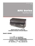
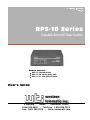
WTI Part No.: 12493 Rev. D RPS-10 Series Expandable Remote AC Power Switches Models Covered: RPS-10 Standard Unit RPS-10 HD Heavy Duty Unit RPS-10 EC 220/230 VAC Unit User's Guide 5 Sterling · Irvine · California 92618 (949) 586-9950 · Toll Free: 1-800-854-7226 Fax: (949) 583-9514 · http://www.wti.com Table of Contents 1. Introduction . . . . . . . . . . . . . . . . . . . . . . . . . . . . . . . . . . . . . . . . . . . . . . 1 2. Unit Description. . . . . . . . . . . . . . . . . . . . 2.1. Front Panel. . . . . . . . . . . . . . . . . . . . 2.2. Back Panel . . . . . . . . . . . . . . . . . . . . 2.2.1. RPS-10 and RPS-10 HD Back Panel 2.2.2. RPS-10 EC Back Panel . . . . . . . . 2.3. Back Panel Components . . . . . . . . . . . . . . . . . . . . . . . . . . . . . . . . . . . . . . . . . . . . . . . . . . . . . . . . . . . . . . . . . . . . . . . . . . . . . . . . . . . . . . . . . . . . . . . . . . . . . . . . . . . . . . . . . . . . . . . . . . . . . . . . . . . . . . . . . . . . . . . . . . . . . . . . . . . . 2 2 2 2 3 3 3. Installation . . . . . . . . . . . . . . . . 3.1. Setting the Address . . . . . . . . 3.2. Set-Up Switches. . . . . . . . . . 3.3. Linking Modules . . . . . . . . . 3.4. Control Port Connection . . . . . 3.4.1. Connecting to a Modem 3.5. Power Connection . . . . . . . . 3.6. Test for Proper Installation . . . . . . . . . . . . . . . . . . . . . . . . . . . . . . . . . . . . . . . . . . . . . . . . . . . . . . . . . . . . . . . . . . . . . . . . . . . . . . . . . . . . . . . . . . . . . . . . . . . . . . . . . . . . . . . . . . . . . . . . . . . . . . . . . . . . . . . . . . . . . . . . . . . . . . . . . . . . . . . . . . . . . . . . . . . . . . . . . . . . . . . . . . . . . . . . . . . 4 4 5 6 7 7 7 8 4. Operation. . . . . . . . . . . . . . . . . . . . . . . . . . . . . . . . . . . . . . . . . . . . . . . . 9 4.1. Optional Accessories . . . . . . . . . . . . . . . . . . . . . . . . . . . . . . . . . . . . . 11 4.1.1. Three Module Rack . . . . . . . . . . . . . . . . . . . . . . . . . . . . . . . . . 11 4.1.2. Snap Adapters . . . . . . . . . . . . . . . . . . . . . . . . . . . . . . . . . . . . 12 4.2. Cable Wiring Diagrams . . . . . . . . . . . . . . . . . . . . . . . . . . . . . . . . . . . . 13 . . . . . . . . . . . . . . . . . . . . . . . . . . . . . . . . . . . . . . . . . . . . . . . . . . . . . . . . Appendices A. Specifications. . . . . . . . . . . . . . . . . . . . . . . . . . . . . . . . . . . . . . . . . . . . . 14 B. FCC Statement: . . . . . . . . . . . . . . . . . . . . . . . . . . . . . . . . . . . . . . . . . . . 15 C. Customer Service . . . . . . . . . . . . . . . . . . . . . . . . . . . . . . . . . . . . . . . . . . 15 List of Figures 1. 2. 3. 4. 5. 6. 7. 8. 9. 10. Front Panel . . . . . . . . . . . . . . . . . . . . . . . . . . . . . . . . . . . . . . . . . . . . . . 2 RPS-10 and RPS-10 HD Back Panel . . . . . . . . . . . . . . . . . . . . . . . . . . . . . . . 2 RPS-10 EC Back Panel . . . . . . . . . . . . . . . . . . . . . . . . . . . . . . . . . . . . . . . 3 RPS-10 Cable Layout . . . . . . . . . . . . . . . . . . . . . . . . . . . . . . . . . . . . . . . . 6 RS232 Interface Schematic . . . . . . . . . . . . . . . . . . . . . . . . . . . . . . . . . . . . . 7 Three Module Tray . . . . . . . . . . . . . . . . . . . . . . . . . . . . . . . . . . . . . . . . . 11 Optional Snap Adapters . . . . . . . . . . . . . . . . . . . . . . . . . . . . . . . . . . . . . . 12 Cable Wiring Diagram; RPS-10 to Modem . . . . . . . . . . . . . . . . . . . . . . . . . . . 13 Cable Wiring Diagram; RPS-10 to PC (25 Pin) . . . . . . . . . . . . . . . . . . . . . . . . 13 Cable Wiring Diagram; RPS-10 to PC (9 Pin) . . . . . . . . . . . . . . . . . . . . . . . . . 13 i 1. Introduction Network equipment sometimes "locks-up", making it impossible to communicate. In the past, this situation required a trip to the installation site, simply to flip the power switch off and then back on again. When a distant installation site makes this trip costly or time consuming, the RPS-10 can do it for you! The RPS-10 allows you to remotely switch devices using simple ASCII commands sent via modem or cable. A convenient, modular design allows the RPS-10 to expand to provide control of up to 10 modules located throughout your facility. Each addressable module can be switched On, Off or toggled. Three different models are available to allow the RPS-10 to fit the requirements of a variety of applications: · RPS-10 Standard Unit: Remotely switch AC power On or Off, or initiate a toggle sequence with a user defined delay period. · RPS-10 HD Heavy Duty Unit: Features heavy duty, solid state construction for applications that require high volume, repetitive switching of AC powered devices. · RPS-10 EC 220/230 VAC Unit: Features European style IEC connectors for operation using 220/230 VAC, 50 Hz power. This User’s Guide covers all three RPS-10 models. Throughout this publication, all three models are referred to as the "RPS-10". Applications · Remote Network Management · Re-Boot Data Communications Equipment · Take Equipment Out-of-Service · PC Control of AC Power - Switch Any AC Powered Device On or Off, Using ASCII Commands Sent Via Modem Page 1 2. Unit Description 2.1. Front Panel Figure 1: Front Panel À AC ON: Lights when power to the Switched Outlet is ON. Á LINK: Flashes when command data is received. Â RDY: Lights when AC Power is applied and the module is ready to receive commands. Does not indicate the ON/OFF condition of the Switched Outlet. 2.2. Back Panel The back panel for each RPS-10 model differs slightly as shown in Figures 2 and 3. Individual back panel components are described in detail in Section 2.3. 2.2.1. RPS-10 and RPS-10 HD Back Panel Figure 2: RPS-10 and RPS-10 HD Back Panel 1. 2. 3. 4. 5. Switched AC Outlet RS232 Control Port (Master Module Only) SetUp Switches Rotary Address Switch RJ11 Link Ports 6. 7. Circuit Breaker (RPS-10 = 10 Amps, RPS-10 HD = 15 Amps) Power Cable Page 2 RPS-10 Series Remote Power Switches, User's Guide Unit Description 2.2.2. RPS-10 EC Back Panel Figure 3: RPS-10 EC Back Panel 1. 2. 3. 4. Switched AC Outlet (IEC) RS232 Control Port (Master Module Only) SetUp Switches Rotary Address Switch 5. 6. 7. RJ11 Link Ports 5 Amp Circuit Breaker IEC Input 2.3. Back Panel Components À Switched Outlet: (RPS-10, RPS-10 HD, and RPS-10 EC) For connection to your AC powered device (see Appendix A for power specifications). Á RS232 Control Port (Master Module Only): A DB9 connector used to connect the RPS-10M Master Module to your modem or local control device. Â SetUp Switches: A bank of 4 switches used to set baud rate, toggle delay, and power up default (see Section 3.2). Ã Address Selection Switch: A rotary dial switch, used to select the address for each Module. Ä Link Ports: Two RJ11 jacks used for connection between modules. Switching commands and status reports are sent via the Link Ports. Page 3 3. Installation The installation procedure consists of the steps listed below. For more information, please refer to the section(s) indicated. 1. Set the Address for each module (Section 3.1). 2. Configure the Set-Up Switches (Section 3.2). 3. Use RJ11 Cables to link RPS-10 Modules (Section 3.3). Caution: Do not connect the Link Ports to a telephone circuit. 4. Connect your modem or local PC to the control port on the back panel of the RPS-10M Master Module (Section 3.4). 5. Connect your Switched Device to an RPS-10 Module's Switched Outlet (or Terminal Block). Connect each Module to your AC power supply (Section 3.5). 6. Test the RPS-10 as described in Section 3.6. 3.1. Setting the Address The rotary dial on the back panel selects the address for each module. Make certain the module is powered OFF (power cable unplugged), then turn the dial to select the desired address. Note: • The address for the Master Module must always be set to "0" (zero). The address for each Satellite Module should be set from 1 to 9. • Each module in the link must be assigned its own unique address. Do not assign duplicate addresses. • It is not necessary to set each Satellite Module address in consecutive numerical order. Module addresses can be set in any order. • To change an address after the RPS-10 has been installed, unplug the module from the AC power supply, then turn the rotary dial to select the new address. Note that the address setting should only be changed while power is Off; the RPS-10 will read the new address when power is restored. Page 4 RPS-10 Series Remote Power Switches, User's Guide Installation 3.2. Set-Up Switches Prior to connecting AC power to the RPS-10 Modules, configure the Set-Up Switches on each module according to the requirements of your application. Switch Function Up Down 1 Data Rate 2400 bps 9600 bps 2 Toggle Delay 10 Sec. 5 Sec. 3 Power-Up Default On Last 4 Spare — — Switch 1, Data Rate: Sets the communication speed (baud rate) between the RPS-10M Master Module and ASCII control device, as well as the communication speed between the Master Module and each Satellite Module. Note: The communication speed setting for each Satellite Module must match the Master Module. Switch 2, Toggle Delay: Determines the length of time power will remain OFF when a Toggle sequence is initiated. Switch 3, Power-Up Default: Determines how each switched outlet will react after an interruption in AC power. · When Switch 3 is placed in the Up position, the Switched Outlet will always return to the ON state when power is restored to the module. · When Switch 3 is placed in the Down position, the Switched Outlet (or Terminal Block) will return to the state that it was in prior to the power interruption. For example, if the Outlet was OFF prior to the power interruption, the Outlet will return to the OFF position after power is restored. Switch 4: Spare. Note: It is not necessary to power the module OFF in order for the new settings to take effect. Page 5 RPS-10 Series Remote Power Switches, User's Guide Installation 3.3. Linking Modules Connect straight wired RJ11 cables between the Link Ports to link the RPS-10 Master Module and Satellite Modules as shown in Figure 4 below. • • • • Note: Use straight wired RJ11 cable to link RPS-10 Modules. Do not use cross-wired telephone cable. The total length of cabling between the first module in the link and the last module in the link cannot exceed 2,000 feet. Each RPS-10 Module includes two interchangeable link ports. Either port can be used for connection to the next module or previous module. The installation can include a mixture of different RPS-10 Models. For example, an RPS-10 Master Module could be linked to six RPS-10 Standard Satellite Modules and three RPS-10 HD Heavy Duty Satellite Module. Figure 4: RPS-10 Cable Layout Page 6 RPS-10 Series Remote Power Switches, User's Guide Installation Figure 5: RS232 Interface Schematic 3.4. Control Port Connection The RS232 Control Port is a male, DB9 connector, used for connection to a PC or external modem. The Control Port employs a DTE configuration, similar to an AT computer. WTI offers a complete selection of Snap Adapters to simplify connection to your PC or modem. Please refer to Section 4.1.2 for more information on RJ11 modular adapters. 3.4.1. Connecting to a Modem When connecting the Control Port to an external modem, use a standard AT to modem cable. Make certain the modem is initialized at the same baud rate as the RPS-10. The modem must be placed in Auto-Answer mode, and set to answer in one ring. Please refer to the user’s guide for your external modem in order to determine the appropriate AT command string. 3.5. Power Connection 1. Plug the Switched Device into the Switched Outlet. • RPS-10: Total load for each module cannot exceed 10 Amps. • RPS-10 HD: Total load for each module cannot exceed 15 Amps. • RPS-10 EC: Total load for each module cannot exceed 5 Amps. 2. Connect the power cord from each RPS-10 Module to your AC power supply. Page 7 RPS-10 Series Remote Power Switches, User's Guide Installation 3.6. Test for Proper Installation After installation, the following test should be performed to make certain all modules are operating correctly. 1. Establish a connection with the RPS-10M Master Module. a) Via Modem: Start your terminal emulation software, and dial the number for the modem connected to the Master Module. After a brief pause, the unit will send the "RPS-10 READY" message b) Direct Connect: If your PC is connected directly to the RPS-10 Control Port, start your terminal emulation software. c) Make certain the terminal emulation software is set for the correct baud rate to match the Master Module (see Section 3.2). Terminal emulation software should also be set for 8 bits, no parity. 2. After connection is established, tap the Space Bar several times. When the Space Bar is pressed, the LINK indicator on each RPS-10 Module should flash briefly. If the LINK indicator does not flash to indicate the Space characters have been received, check the following: a) Make certain all modules are connected to an AC power supply. b) Make certain the RJ11 cables, which link the modules, are straight wired, and firmly seated in the Link Ports. c) Make certain the communication speed for the RPS-10 Master Module, has been set to match your communications program. d) Make certain the Communication speed of each Satellite Module has been set to match the RPS-10M Master Module. e) Make certain that the same address has not been assigned to two or more RPS-10 Modules. Each module must have its own unique address. Page 8 4. Operation Each RPS-10 module can be switched or toggled by an ASCII command string sent to the Master Module control port. The Control Device must send ASCII characters at the same data rate as the RPS-10 Module(s). The RPS-10 will accept any parity, but will always answer back at 8 bits, no parity. The command string consists of nine contiguous characters. The first six characters are ASCII control codes. These six characters constitute a "fixed password" that restricts access to the RPS-10. The seventh character is the address of the Module(s) that will receive the command, and the eighth character is the operation code. The last character in the command string is an ASCII Carriage Return (^M). 1. Establish connection with the RPS-10M Master Module. If you are communicating via modem, the system will pause briefly while connecting, and then send the "RPS-10 READY" message. 2. Enter the desired ASCII command string. The command string uses the format described below. ^B^X^X^B^X^Xac^M (^ = Control Code) Where: ^B^X^X^B^X^X Is the RPS-10's "fixed password". a c ^M Is the Module Address. This indicates the address of the module that will receive the command. a = 0-9 Indicates the address of the module that will receive the command. a = * Indicates that the command should be sent to all modules. Is the Operation Code. This indicates the task to be performed: c = 0 Switch AC OFF - Instructs RPS-10 to switch OFF the Outlet for the selected Module(s) c = 1 Switch AC ON - Instructs RPS-10 to switch ON the Outlet for the selected Module(s) c = T Toggle AC (OFF - Delay - ON) - Instructs the RPS-10 to initiate a toggle sequence at the selected Module(s). Note that this command is case sensitive, and must always be entered as an upper case "T". c = ? Read and Display Status - Instructs RPS-10 to display status of selected Module(s). Is the ASCII code for a carriage return Page 9 RPS-10 Series Remote Power Switches, User's Guide Operation Examples: To toggle the Switched AC Outlet on the RPS-10 Module at Address "3", send the following command: ^B^X^X^B^X^X3T^M To set the Switched Outlet on the RPS-10 Module at Address "4" to the Off position, send the following command: ^B^X^X^B^X^X40^M To display the status of all linked RPS-10 Modules, send the following command: ^B^X^X^B^X^X*?^M Note: • After executing each command, the RPS-10 will send a "COMPLETE" message. Do not enter additional commands until the previous command is complete. • When operating at 9600 bps, there will be a 0.5 second delay before the next command may be entered. At 2400 bps, there will be a 1.5 second delay. Page 10 RPS-10 Series Remote Power Switches, User's Guide Operation 4.1. Optional Accessories 4.1.1. Three Module Rack WTI offers an optional three module rack, which fits most standard instrument racks. To assemble the rack, refer to Figure 6 and proceed as follows: 1. Remove rubber feet from bottom of each module. 2. Attach right bracket (4) to rack tray (6) using two black, Phillips head screws (3) supplied. Repeat step for left bracket (7). 3. Place three modules (1) in rack tray (6). Make certain LEDs are visible through cutouts in front of tray. 4. Use two silver, slot head screws (5) to attach each module to rack tray (6). 5. Link modules using two RJ11 cables (2) supplied. Figure 6: Three Module Tray 1. 2. 3. 4. RPS-10 Modules RJ11 Link Cables (2 ea.) Phillips Head Screws (2 ea.) Right Rack Bracket 5. 6. 7. 8. Slot Head Screws (6 ea.) Rack Mount Tray Left Rack Bracket Phillips Head Screws (2 ea.) Page 11 RPS-10 Series Remote Power Switches, User's Guide Operation 4.1.2. Snap Adapters WTI offers a complete selection of snap adapters and cables designed to simplify connection between the RPS-10M Master Module and your Modem or PC. These snap adapters and cables are described in the table below and in Figure 7. WTI Part No. Description SA-28F DB9 to RJ11 Adapter AC-LL Straight Wired RJ11 Cable (LL = Length, 10 to 150 ft.) SA-12F RJ11 to 25 Pin PC (DTE) Adapter SA-9F RJ11 to 9 Pin PC (DTE) Adapter SA-30M RJ11 to 25 Pin Modem (DCE) Adapter Figure 7: Optional Snap Adapters Page 12 RPS-10 Series Remote Power Switches, User's Guide Operation 4.2. Cable Wiring Diagrams Figure 8: Cable Wiring Diagram; RPS-10 to Modem Figure 9: Cable Wiring Diagram; RPS-10 to PC (25 Pin) Figure 10: Cable Wiring Diagram; RPS-10 to PC (9 Pin) Page 13 RPS-10 Series Remote Power Switches, User's Guide Appendices A. Specifications Switched Outlet / Terminal Block: RPS-10: 1 Plug, Rated at 115 VAC @ 10 Amps Max. RPS-10 HD: 1 Plug, Rated at 115 VAC @ 15 Amps Max. RPS-10 EC: 1 Plug, Rated at 220 VAC @ 5 Amps Max. Control Port: RS232, DB9 Male Connector, AT/DTE Configuration Link Port: RS-485, Dual RJ11 jacks, 2,000 feet Total End-to-End Link Distance Link Address: Rotary Switch Selects 0 - 9 Address Coding: Serial RS232 ASCII, 8 Bits, No Parity Data Rate: 2400, 9600 bps - Switch Selectable LEDs: Ready, Link Activity, AC Power On Power: RPS-10: Internal 115 VAC, 60 Hz (10 Amps Maximum Load) RPS-10 HD: 115 VAC, 60 Hz (15 Amps Maximum Load) RPS-10 EC: Internal 220/230 VAC, 50 Hz (5 Amps Maximum Load) Size: 1.65" x 5.50" x 5.0" (H x W x D) Weight: 2 lbs. Shipping Weight Rack Tray: Optional 19" Rack Holds up to 3 Modules 1.75" x 19.00" x 5.50" - One Rack Unit Page 14 RPS-10 Series Remote Power Switches, User's Guide Appendices B. FCC Statement: This device complies with part 15 of the FCC Rules. Operation is subject to the following two conditions: 1. This device may not cause harmful interference, and 2. This device must accept any interference received, including interference that may cause undesired operation. C. Customer Service Customer Service hours are from 8:00 am to 5:00 pm (PST), Monday through Friday. When calling, please be prepared to provide the product serial number and a description of the symptoms. If the unit should need to be returned for factory repair, it must be accompanied by a Return Authorization Number from Customer Service. WTI Customer Service 5 Sterling, Irvine, California 92618 Local Phone: (949) 586-9950 Toll Free Service Line: 1-888-280-7227 Service Fax: (949) 457-8138 Email: [email protected] Trademark and Copyright Information WTI and Western Telematic are trademarks of Western Telematic Incorporated. All other product names mentioned in this publication are trademarks of their respective companies. Information and descriptions contained herein are the property of Western Telematic, Inc.. Such information and descriptions may not be copied, disseminated or distributed without the express written consent of Western Telematic, Incorporated. ©Copyright Western Telematic, Inc., 1994, 1997, 2000. All right reserved. December 1997, November 2000 WTI Part Number: 12493 Rev. D Page 15