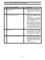
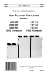
1
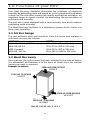
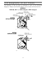
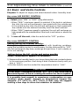
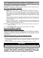
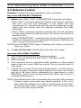
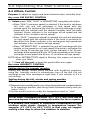
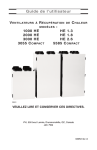
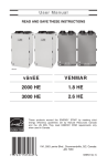
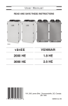
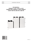
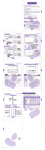
User’s Manual
Read and save these instructions.
Heat Recovery Ventilators
models:
1000 HE
HE 1.3
2000 HE
HE 1.8
HE 2.6
3000 HE
3055 Compact 5585 Compact
VB0021
VVI, 550 Lemire Blvd., Drummondville, Qc, Canada J2C 7W9
04/01
#02053
Congradulations!
You have made an excellent choice! The operating principle of your
Heat Recovery Ventilator will protect your house and give you personnal
comfort you have never known before.
We have prepared this Operating Guide especially for you. Please
read it carefully to ensure you obtain full benefit from your Heat
Recovery Ventilator unit. Over the coming months, you will increasingly
appreciate the feeling of living in a more comfortable house.
Please take note that this manual uses the following symbols to
emphasize particular information:
! WARNING
Identifies an instruction which, if not followed, might cause serious
personal injuries including possibility of death.
CAUTION
Denotes an instruction which, if not followed, may severely damage
the unit and/or its components.
NOTE: Indicates supplementary information needed to fully complete an
instruction.
We welcome any suggestions you may have concerning this
manual and/or the unit, and we would appreciate hearing your comments
on ways to better serve you. Please forward all correspondence to us at
the address indicated on the product registration card included with this
manual.
CAUTION
Make sure at all times that the outside hoods are free from any snow
during the winter season. It is important to check your unit during a
big snow storm, so it doesn’t draw in any snow. If this is the case,
please operatre the unit in the circulation mode, or OFF mode, for a
few hours.
Do not use your HRV during construction or renovation of your
house or when sanding drywall. This type of dust may damage your
system.
Since the electronic control system of the unit is incorporated with
a microprocessor, it may not operate correctly because of external
noise or very short power failure. If this happens, unplug the unit and
wait approximately 10 seconds. Then, plug the unit in again.
I
Table of contents
1.0
Functions of your HRV . . . . . . . . . . . . . . . . . . . . . . . . . . 1
1.1 Air Exchange . . . . . . . . . . . . . . . . . . . . . . . . . . . . . . . . . . . . . . . . . . . 1
1.2 Heat Recovery . . . . . . . . . . . . . . . . . . . . . . . . . . . . . . . . . . . . . . . . . . 1
1.3 Circulation . . . . . . . . . . . . . . . . . . . . . . . . . . . . . . . . . . . . . . . . . . . . . 2
2.0
Diagrams of air flows . . . . . . . . . . . . . . . . . . . . . . . . . . 3
3.0
Description of unit . . . . . . . . . . . . . . . . . . . . . . . . . . . . 5
4.0
Operating the Wall Control . . . . . . . . . . . . . . . . . . . . . . 7
4.1
4.2
4.3
4.4
5.0
Maintenance . . . . . . . . . . . . . . . . . . . . . . . . . . . . . . . . 12
5.1
5.2
6.0
Basic and Venta Controls . . . . . . . . . . . . . . . . . . . . . . . . . . . . . . . . . 8
Electro and Supra Controls . . . . . . . . . . . . . . . . . . . . . . . . . . . . . . . 9
Detector Control . . . . . . . . . . . . . . . . . . . . . . . . . . . . . . . . . . . . . . . 10
Ultima Control . . . . . . . . . . . . . . . . . . . . . . . . . . . . . . . . . . . . . . . . . 11
Regular Maintenance . . . . . . . . . . . . . . . . . . . . . . . . . . . . . . . . . . .12
Annual Maintenance . . . . . . . . . . . . . . . . . . . . . . . . . . . . . . . . . . .12
Troubleshooting . . . . . . . . . . . . . . . . . . . . . . . . . . . . . . 13
II
1.0 Functions of your HRV
Your Heat Recovery Ventilator eliminates the problems of excessive
humidity by exhausting stale and humid air to the outside and by drawing
in fresh air. The unit offers superior air quality and fresh air sensation, an
important factor to overall comfort, by eliminating the accumulation of
pollutants and humidity.
The unit also comes equipped with a heat recovery core which reduces
ventilating costs in winter.
The Heat Recovery Ventilator is a Ventilation system which carries out
three main operation:
1.1 Air Exchange
The unit exhausts stale and humid air from the house and replaces it
with fresh air from the outside.
MODELS
1000 HE / HE 1.3 / 3055 Compact
2000 HE/ HE 1.8
5585 Compact
3000 HE / HE 2.6
RATES
30 to 60 l/s (65 to 130 cfm)
55 to 93 l/s (115 to 197 cfm)
55 to 92 l/s (117 to 195 cfm)
85 to 141 l/s (180 to 300 cfm)
1.2 Heat Recovery
During winter, the unit recovers the heat contained in the stale air before
it is exhausted, and transfers it to the fresh air drawn from the outside
(reverse process in summer).
Example: (in winter)
FRESH AIR FROM OUTSIDE
0°C/32°F
STALE AIR TO OUTSIDE
3°C/37°F
STALE AIR FROM BUILDING
22°C/72°F
VF0024
FRESH AIR TO BUILDING
19°C/66°F
2000 HE, 3000 HE, HE 1.8, HE 2.6
1
1.0 Functions of your HRV (cont’d)
1.2 Heat Recovery
(cont’d)
Example: (in winter)
FRESH AIR TO BUILDING
18°C/64°F
STALE AIR TO OUTSIDE
4°C/39°F
FRESH AIR FROM OUTSIDE
0°C/32°F
STALE AIR FROM BUILDING
22°C/72°F
VF0026
1000 HE, HE 1.3, 3055 Compact, 5585 Compact
1.3 Circulation
(available with ULTIMA control only)
During the circulation mode, when the selected level of humidity is
reached, the unit stops to exchange air with the exterior. Continuous
circulation is thus undertaken inside the home and insures the purification
of the ambiant air. A mechanical filter traps the large dust particles
(those visible to the eye).
2
2.0 Diagrams of Air Flows
The direction of the air flow is indicated in each of the following
diagrams. Please note that the stale air never mixes with the fresh air.
MODELS
1000 HE, HE 1.3, 3055 Compact, 5585 Compact
FRESH AIR
FRESH AIR TO BUILDING
FROM OUTSIDE
STALE AIR
STALE AIR
FROM BUILDING
TO OUTSIDE
during
air exchange
VF0010
during
defrost mode
STALE AIR
FROM BUILDING
FILTERED AIR
TO BUILDING
VF0003
3
2.0 Diagrams of Air Flows
(cont’d)
MODELS
2000 HE, 3000 HE, HE 1.8, HE 2.6
during
air exchange
FRESH AIR
TO BUILDING
STALE AIR
FROM BUILDING
FRESH AIR
FROM OUTSIDE
STALE AIR
TO OUTSIDE
VF0025
during circulation
and defrost
FILTERED AIR
TO BUILDING
VF0002
4
STALE AIR
FROM BUILDING
3.0 Description of the Unit
1) Stale air intake port: is connected to the registers located in the
larger rooms of the house.
2) Fresh air port: brings fresh air from the outside into the unit.
3) Exhaust port: exhausts stale air to the outside, after the air has
transferred its heat inside the heat recovery core.
4) Distribution port: distributes fresh air into the house, after it has
absorbed the heat of the stale air in the heat recovery core.
5) Foam filter: traps the dust contained in the air and prevents the heat
recovery core from becoming obstructed.
6) Heat recovery core: is a counterflow type for 2000 HE, 3000 HE,
1.8 HE, 2.6 HE models and is a crossflow type for the other models.
It transfers the heat between the two air streams.
7) Blowers: draw fresh air from the outside and exhaust stale air to the
outside. The blower wheels are driven by two motors for 2000 HE,
3000 HE, 1.8 HE, 2.6 HE models. The other models have just one motor.
8) Capacitor: is indispensable to proper motor operation.
9) Condensation tray: is used to capture the water produced during
heat transfer and defrost. (in cold climate)
10) Drainage tube: is connected to the condensation tray and serves to
drain the water within.
11) Electronic control circuit: located inside the electrical box,
insures proper operation of the unit.
12) Automatic defrost unit: consists of one damper actuator,
dampers and the related controls. The defrost cycle is electronically
controlled in response to the outside temperature (-5°C (23°F) to
-40°C (-40°F)) and will increase in frequency as the temperature
decreases. Its duration is of 5 or 6 minutes according to models.
13) Control Connector: located inside the electrical box, allows to
connect the control and override switch as a timer, a dehumidistat or
a switch.
14) Electrical cord: for 120V electrical supply.
5
2
4
1
14
3
MODELS
1000 HE, HE 1.3,
3055 Compact,
5585 Compact
12
11
13
6
8
7
5
10 9
VL0003
MODELS
2000 HE, 3000 HE, HE 1.8, HE 2.6
1
4
14
2
3
12
5
6
7
8
7
11
13
5
10
9
VL0012
6
4.0 Operating the Wall Controls
The following illustrations show the main controls. Refer to next pages
for operating instructions.
1000 HE
2000 HE
3000 HE
HE 1.3, HE 1.8, HE 2.6
3585 Compact
5585 Compact
CONDENSATI0N
ATI0N CONTROL
A
ER
MM
SU
-20 C
-4°
CO
NE
AIR SUPPLY
LY CONTROL
L
OFF
MIN.
AIR
EXCHANGE
CH
HA
MAX.
VC0035
VC0010
BASIC
VENTA
CONDENSATI0N
ATI0N CONTROL
A
ER
MM
SU
C
-4
M
E
ZO
C
41°F
CONDENSATION CONTROL
MAXIMUM SPEED
AIR EXCHANGE IN PROGRESS
AIR SUPPLY
LY CONTROL
L
MIN.
MAX.
20 M
MIN
N.
N.
ON
CONTINUOUS
40 MIN.
M
OF
OFF
INTERMITTENTT
VC0036
VC0011
ELECTRO
POLLUTANT
TANT CONTROL
T
I
SUPRA
Pollutant
TY
E
POLLUTANT
TTANT CONTROL
MAXIMUM SPEED
AIR EXCHANGE IN PROGRESS
AIR SUPPLY
LY CONTROL
L
MIN.
MAX.
20 MIN
M N.
N.
ON
CONTINUOUS
40 MIN.
M
OF
OFF
INTERMITTENTT
VC0037
VC0013
DETECTOR
ULTIMA
7
4.0 Operating the Wall Controls
(cont’d)
4.1 Basic and Venta Controls
Purpose:To adjust air supply and select desired indoor humidity level.
ADJUSTING AIR SUPPLY CONTROL
1)
Select speed “MIN.” or “MAX.” using slide switch.
• When “MIN.” (minimum speed) is selected, if the knob is set above
the click, the unit will exchange in low speed with the outside and
if it is set below the click, the unit will exchange on high speed with
the outside until the desired humidity level has been reached.
• When “MAX.” (maximum speed) is selected, the unit will exchange on
high speed with the outside either if the knob is set below or above the
click.
2)
To turn off the unit, slide the switch at the “OFF” position.
ADJUSTING HUMIDITY CONTROL
Setting during the summer months:
During this period, unless being afflicted with breathing problems,
using the humidity control is unnecessary. Set the slide switch to ‘’OFF’’.
(Do not exchange in day time; exchange at night time, if cool outside, or
if it is not raining.)
Setting during the fall, winter and spring months:
(When condensation appears on windows)
1) Determine the humidity level in your house (bring the knob counterclockwise
to its maximum position, then bring it back clockwise slowly until you
hear a “click”).
2) Set the knob to one line under this temperature level or “click”.
CAUTION
Do not select a temperature below -20°C (-4°F). This could lead to
excessive dryness in the air causing discomfort for the occupants.
It is possible (and normal) to experience condensation on your
windows when drastic changes in temperature happen (for
example: -5°C (23°F) to -20°C (-4°F)). In that case, we suggest
waiting a few days to allow the situation to stabilize.
8
4.0 Operating the Wall Controls
(cont’d)
4.2 Electro and Supra Controls
Purpose:To adjust air supply and select desired indoor humidity level.
ADJUSTING AIR SUPPLY CONTROL
1)
Select speed “MIN.”,“MAX.” or INTERMITTENT using the push button.
• When “MIN.” (minimum speed) is selected, if the knob is set above
the click, the unit will exchange in low speed with the
outside and if it is set below the click, the unit will exchange on high
speed with the outside until the desired humidity level has been
reached.
• When “MAX.” (maximum speed) is selected, the unit will exchange
on high speed with the outside either if the knob is set below or
above the click.
• When “INTERMITTENT” is selected, the unit will exchange with the
outside on low speed (or on high speed if the knob is set below the
click), during 20 minutes per hour.
NOTE: When INTERMITTENT signal is flashing, this means you have to
clean your filters.
2)
To turn off the unit, activate the push button once again.
ADJUSTING HUMIDITY CONTROL
Setting during the summer months:
During this period, unless being afflicted with breathing problems,
using the humidity control is unnecessary; turn off the unit. (Do not
exchange in day time; exchange at night time, if cool outside, or if it is
not raining.)
Setting during the fall, winter and spring months:
(When condensation appears on windows)
1) Determine the humidity level in your house (bring the knob counterclockwise
to its maximum position, then bring it back clockwise slowly until you
hear a “click”).
2) Set the knob to one line under this temperature level or “click”.
CAUTION
Do not select a temperature below -20°C (-4°F). This could lead to
excessive dryness in the air causing discomfort for the occupants.
It is possible (and normal) to experience condensation on your
windows when drastic changes in temperature happen (for
example: -5°C (23°F) to -20°C (-4°F)). In that case, we suggest
waiting a few days to allow the situation to stabilize.
9
4.0 Operating the Wall Controls
(cont’d)
4.3 Detector Control
Purpose:To adjust air supply and detect indoor pollutants.
ADJUSTING AIR SUPPLY CONTROL
1)
Select speed “MIN.”,“MAX.” or INTERMITTENT using the push button.
• When “MIN.” (minimum speed) is selected, if the knob is set above
the click, the unit will exchange in low speed with the
outside and if it is set below the click, the unit will exchange on high
speed with the outside until the detected pollutants has been
exhausted.
• When “MAX.” (maximum speed) is selected, the unit will exchange
on high speed with the outside either if the knob is set below or
above the click.
• When “INTERMITTENT” is selected, the unit will exchange with the
outside on low speed (or on high speed if the knob is set below the
click), during 20 minutes per hour.
NOTE: When INTERMITTENT signal is flashing, this means you have to
clean your filters.
2)
To turn off the unit, activate the push button once again.
ADJUSTING POLLUTANT CONTROL
1.
2.
3.
4.
5.
Set the sensitivity knob at the maximum position.
Plug in the unit and set the AIR SUPPLY CONTROL to MIN.
Wait 5 minutes.
Put a pollution source (cigarette smoke, perfume or other strong
vapors) near the control. Wait one minute. The unit should switch to
high speed.
Unplug the unit, wait 30 seconds and plug back in. Set the knob to
medium (normal) sensitivity before leaving the house. You should
wait up to 48 hours before attempting any adjustments to your
DETECTOR control. (This waiting period will allow the control to
restabilize after the test.)
NOTE: If the pollution level of the surrounding air is very high, this procedure
(5 steps) might not provoke high speed operation. If this is the
case, allow the polluted air to clear by operating the unit at MAX.
for several hours. Then, unplug the unit, wait 30 seconds, plug
back in, and redo the procedure.
10
4.0 Operating the Wall Controls
(cont’d)
4.4 Ultima Control
Purpose:To adjust air supply and select desired indoor humidity level.
ADJUSTING AIR SUPPLY CONTROL
1)
Select speed “MIN.”,“MAX.” or INTERMITTENT using the push button.
• When “MIN.” (minimum speed) is selected, if the knob is set above
the click, the unit will exchange in low speed with the
outside and if it is set below the click, the unit will exchange on high
speed with the outside until the desired humidity level has been
reached. (Green indicator is for exchange at low speed and red
indicator is for circulation at low speed).
• When “MAX.” (maximum speed) is selected, the unit will exchange
on high speed with the outside either if the knob is set below or
above the click. (Green indicator is for exchange at high speed and
red indicator is for circulation at high speed)
• When “INTERMITTENT” is selected, the unit will exchange with the
outside on low speed (or on high speed if the knob is set below the
click), during 20 minutes per hour. (Green indicator is for 20 min.
exchange at low speed and 40 min. OFF and red indicator is for 20 min.
exchange at low speed and 40 min. of circulation at high speed)
NOTE: When INTERMITTENT signal is flashing, this means you have to
clean your filters.
2) To turn off the unit, activate the push button once again.
ADJUSTING HUMIDITY CONTROL
Setting during the summer months:
During this period, unless being afflicted with breathing problems,
using the humidity control is unnecessary; turn off the unit. (Do not
exchange in day time; exchange at night time, if cool outside, or if it is
not raining.)
Setting during the fall, winter and spring months:
(When condensation appears on windows)
1) Determine the humidity level in your house (bring the knob counterclockwise
to its maximum position, then bring it back clockwise slowly until you
hear a “click”).
2) Set the knob to one line under this temperature level or “click”.
CAUTION
Do not select a temperature below -20°C (-4°F). This could lead to
excessive dryness in the air causing discomfort for the occupants.
It is possible (and normal) to experience condensation on your
windows when drastic changes in temperature happen (for
example: -5°C (23°F) to -20°C (-4°F)). In that case, we suggest
waiting a few days to allow the situation to stabilize.
11
5.0 Maintenance
! WARNING
Risk of electric shock. Before performing any maintenance or
servicing, always disconnect the unit from its power source.
5.1 Regular Maintenance
1)
The motors are factory lubricated for life. Lubricating the bearings is
not recommended.
CAUTION
Because the unit is suspended, two people are recommended to
remove or install the heat recovery core.
Do not hold the heat recovery core using its plastic extrusions
as handles.
2) The heat recovery core must be handled with care. We recommend
that it be washed once a year, following the season of most intense
use, in order to insure maximum efficiency of the plastic partitions.
Allow the heat recovery core to soak for 3 hours in a solution of
warm water and mild soap. Rinse under a heavy stream of water.
CAUTION
Hot water and a strong detergent will damage the heat recovery core.
3)
The air filters are washable. Under normal conditions, we recommend
that they be washed every 3 months.
- Use a vacuum cleaner to remove the heaviest portion of accumulated
dust. Then wash in hot water.
4)
Regularly check the screen on the exterior intake hood and clean
when necessary. Also check during very cold weather because ice
may grow on the screen located at the exterior intake hood.
5.2 Annual Maintenance
NOTE: Ask your installer for an annual service contract.
Annual service should include:
1)
Cleaning filters, heat recovery core and the exterior air
intake/exhaust hood.
2)
Cleaning the wheels and the blower blades.
3)
Cleaning the condensation tray with soapy water (make sure that
the drain is not clogged).
4)
Running the system and checking the different operating modes.
5)
Measuring and calibrating rates of flow.
12
6.0 Troubleshooting
TYPES OF PROBLEM
TRY THIS...
1
Nothing works.
• Check if the unit is plugged in.
• Check if the unit is receiving
power from the house circuit
breaker.
2
Condensation on windows.
• Adjust the humidity control
knob as per instructions (see
Section 4).
• Operate the unit at maximum
speed during activities generating
excess humidity (family gatherings,
extra cooking, etc.).
• Leave curtains half-open to
allow air circulation on windows.
• Store wood in a closed room
with a dehumidifier or have the
room well ventilated with outside
air or store the wood outside.
• Do not adjust the thermostat of
your heating system below 18°C (64°F).
3
Air too dry
• Do not adjust your humidity
control below -20°C (-4°F).
• Operate the unit at low speed.
• Temporarily stop air exchange.
• Temporarily use a humidifier.
4
Air too cold at the air supply grille
• Make sure the stale air exhaust hood,
outside the house, is not blocked.
• Operate the unit at low speed.
• Have the system balancing checked.
• Have the unit defrosting system
checked.
• Install a duct heater.
13