1
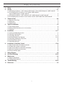
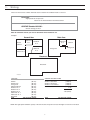
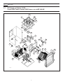
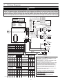
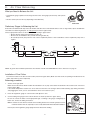
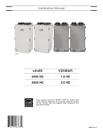
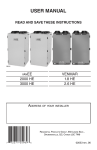
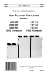
Installation Manual FOR MODELS: VENMAR 1.3 HE, 1.8 HE & 2.6 HE VENMAR 3055 COMPACT & 5585 COMPACT vänEE 1000 HE, 2000 HE & 3000 HE VB0021 04435 rev. D Table of contents 1. 2. Sizing . . . . . . . . . . . . . . . . . . . . . . . . . . . . . . . . . . . . . . . . . . . . . . . . . . . . . . . . . . . . . . . . . . . . . . . . .3 Service . . . . . . . . . . . . . . . . . . . . . . . . . . . . . . . . . . . . . . . . . . . . . . . . . . . . . . . . . . . . . . . . . . . . . .4-7 2.1 3D Drawing for Venmar 1.3 HE, Venmar 3055 Compact, Venmar 5585 Compact & vänEE 1000 HE . . . .4 2.2 Part Ordering Chart for Venmar 1.3 HE, Venmar 3055 Compact, Venmar 5585 Compact & vänEE 1000 HE . . . . . . . . . . . . . . . . . . . . . . . . . . . . . . . . . . . . . . . . . . . . . . . . .5 2.3 3D Drawing for Venmar 1.8 HE, Venmar 2.6 HE, vänEE 2000 HE & vänEE 3000 HE . . . . . . . . . . . . . . . .6 2.4 Part Ordering Chart for Venmar 1.8 HE, Venmar 2.6 HE, vänEE 2000 HE & vänEE 3000 HE . . . . . . . . . .7 3. Technical Data . . . . . . . . . . . . . . . . . . . . . . . . . . . . . . . . . . . . . . . . . . . . . . . . . . . . . . . . . . . . . . . .8-9 3.1 Diagrams of Air Flows . . . . . . . . . . . . . . . . . . . . . . . . . . . . . . . . . . . . . . . . . . . . . . . . . . . . . . . . . . . . . . . . .8 3.2 Dimensions . . . . . . . . . . . . . . . . . . . . . . . . . . . . . . . . . . . . . . . . . . . . . . . . . . . . . . . . . . . . . . . . . . . . . . . . . .9 3.3 Specifications . . . . . . . . . . . . . . . . . . . . . . . . . . . . . . . . . . . . . . . . . . . . . . . . . . . . . . . . . . . . . . . . . . . . . . . .9 4. Typical Installations . . . . . . . . . . . . . . . . . . . . . . . . . . . . . . . . . . . . . . . . . . . . . . . . . . . . . . . . . . . .10 4.1 Fully Ducted System . . . . . . . . . . . . . . . . . . . . . . . . . . . . . . . . . . . . . . . . . . . . . . . . . . . . . . . . . . . . . . . . . .10 4.2 Exhaust Ducted System (Source Point Ventilation) . . . . . . . . . . . . . . . . . . . . . . . . . . . . . . . . . . . . . . . . . . . .10 4.3 Simplified . . . . . . . . . . . . . . . . . . . . . . . . . . . . . . . . . . . . . . . . . . . . . . . . . . . . . . . . . . . . . . . . . . . . . . . . . .10 5. Installation . . . . . . . . . . . . . . . . . . . . . . . . . . . . . . . . . . . . . . . . . . . . . . . . . . . . . . . . . . . . . . . . .11-17 5.1 5.2 5.3 5.4 5.5 5.6 5.7 6. Installation of the Main Control . . . . . . . . . . . . . . . . . . . . . . . . . . . . . . . . . . . . . . . . . . . . . . . .17-20 6.1 6.2 6.3 6.4 6.5 7. 8. 9. Locating and Mounting the Unit . . . . . . . . . . . . . . . . . . . . . . . . . . . . . . . . . . . . . . . . . . . . . . . . . . . . . . . . .11 Planning of the Ductwork . . . . . . . . . . . . . . . . . . . . . . . . . . . . . . . . . . . . . . . . . . . . . . . . . . . . . . . . . . . . . .11 Calculating Duct Size . . . . . . . . . . . . . . . . . . . . . . . . . . . . . . . . . . . . . . . . . . . . . . . . . . . . . . . . . . . . . .11-12 Installing Ductwork and Registers . . . . . . . . . . . . . . . . . . . . . . . . . . . . . . . . . . . . . . . . . . . . . . . . . . . . .12-14 Connecting Flexible Duct to the Unit . . . . . . . . . . . . . . . . . . . . . . . . . . . . . . . . . . . . . . . . . . . . . . . . . . . . .15 Installing Exterior Hoods . . . . . . . . . . . . . . . . . . . . . . . . . . . . . . . . . . . . . . . . . . . . . . . . . . . . . . . . . . . . . . .16 Connecting the Drain . . . . . . . . . . . . . . . . . . . . . . . . . . . . . . . . . . . . . . . . . . . . . . . . . . . . . . . . . . . . . . . . .17 Main Controls with LCD Screen Installation . . . . . . . . . . . . . . . . . . . . . . . . . . . . . . . . . . . . . . . . . . . . . . . .18 All Other Main Controls Installation . . . . . . . . . . . . . . . . . . . . . . . . . . . . . . . . . . . . . . . . . . . . . . . . . . . . . .18 Main Control Electrical Connection (All Models) . . . . . . . . . . . . . . . . . . . . . . . . . . . . . . . . . . . . . . . . . . . .18 Electrical connection to the furnace . . . . . . . . . . . . . . . . . . . . . . . . . . . . . . . . . . . . . . . . . . . . . . . . . . . . . .19 Furnace Interlock Types . . . . . . . . . . . . . . . . . . . . . . . . . . . . . . . . . . . . . . . . . . . . . . . . . . . . . . . . . . . . . . .19 Wiring Diagram . . . . . . . . . . . . . . . . . . . . . . . . . . . . . . . . . . . . . . . . . . . . . . . . . . . . . . . . . . . . . . . .20 Air Flow Balancing . . . . . . . . . . . . . . . . . . . . . . . . . . . . . . . . . . . . . . . . . . . . . . . . . . . . . . . . . .21-22 Maintenance . . . . . . . . . . . . . . . . . . . . . . . . . . . . . . . . . . . . . . . . . . . . . . . . . . . . . . . . . . . . . . . . . .22 9.1 Regular Maintenance . . . . . . . . . . . . . . . . . . . . . . . . . . . . . . . . . . . . . . . . . . . . . . . . . . . . . . . . . . . . . . . . .22 9.2 Prolonged Maintenance . . . . . . . . . . . . . . . . . . . . . . . . . . . . . . . . . . . . . . . . . . . . . . . . . . . . . . . . . . . . . . .22 10. Troubleshooting . . . . . . . . . . . . . . . . . . . . . . . . . . . . . . . . . . . . . . . . . . . . . . . . . . . . . . . . . . . . .23-24 11. References . . . . . . . . . . . . . . . . . . . . . . . . . . . . . . . . . . . . . . . . . . . . . . . . . . . . . . . . . . . . . . . . . . . .24 2 1. Sizing These are the two most common methods used to evaluate the ventilation needs of a house: CSA F326: • High speed: 10 cfm per room 20 cfm for the master bedroom and the basement • Low speed: 40-60% of high speed ASHRAE Standard 62-2001: • 0.35 air change per hour Refer to ventilation code of your area to determine which method to use. Example: Main floor Second floor Washroom no.1 Master bedroom Washroom no. 2 Bedroom no. 2 Dining room Living room Bedroom no. 3 Kitchen Bedroom no.1 920 ft² 920 ft² Basement Basement 920 ft² VH0003A CSA F326 Kitchen Dining room Living room Master bedroom Bedroom no. 1 Bedroom no. 2 Bedroom no. 3 Washroom no. 1 Washroom no. 2 Basement Total ASHRAE Standard 62-2001 (10 cfm) (10 cfm) (10 cfm) (20 cfm) (10 cfm) (10 cfm) (10 cfm) (10 cfm) (10 cfm) (20 cfm) 120 cfm (high speed) Volume of basement Volume of main floor Volume of second floor Total volume Total (7,360 ft³) (7,360 ft³) (7,360 ft³) (22,080 ft³) x .35 7,728 ft³/hr ÷ 60 (min/hr) 129 cfm (high speed) NOTE: The high speed ventilation capacity of the unit should correspond to at least the higher of these two total values. 3 2. Service 2.1 3D DRAWING FOR VENMAR 1.3 HE, VENMAR 3055 COMPACT, VENMAR 5585 COMPACT AND VÄNEE 1000 HE 2 3 1 4 5 6 6 7 9 14 10 11 16 32 29 28 15 13 25 8 17 12 27 24 18 23 26 25 31 22 8 21 30 19 VL0005 4 19 20 2. Service 2.2 PARTS ORDERING CHART FOR VENMAR 1.3 HE, VENMAR 3055 COMPACT, VENMAR 5585 COMPACT AND VÄNEE 1000 HE (cont’d) No Description Venmar 1.3 HE 02021 1 2 2 3 4 5 6 7 8 9 10 11 12 13 14 15 16 17 18 18 19 19 20 21 22 23 24 24 24 25 26 27 28 29 30 31 31 31 32 Double Collar 6” Single Collar 6” Single Collar 7” 01177 Plastic Hole Plug ½” 01581 Strain Relief Bushing SR-7K-2 00660 Strain Relief Bushing SR-2M-4 00525 Insulated Damper 12459 Insulated Rect. Damper 12460 Shaft Assembly 02023 Damper Motor Rod 2.812” 11891 Rubber Grommet no. 2852 00248 Damper Motor Rod 5.250” 11892 Thermistor Kit 12895 Machine Screw 6-32 x 3/8” 00080 Electronic Board 13038 Machine Screw 10-24 x 1 1/4” 00083 Nylon Spacer ¼” DIA. x 1” no. 6-32 00703 Lock Nut no. 10-24 01689 Core 13.5” x 13.5” x 13” 01817 Core 13.5” x 13.5” x 7.875” Filter 12 15/16” x 13 1/2” x 3/8” 01234 Filter 7 13/16” x 13 1/2” x 3/8” Door Assembly 13395 6W Damper Actuator Assembly 02017 Plastic Soft Joint 02031 Nylon Washer 0.875” ID x 1.750”OD 02059 3055 Cent. Wheel 6.29” DIA. (right) Wheel 6.290” DIA. x 2.396” (right) 03093 Dble Cent Wheel 7.062”DIA x1.31”(right) Anchor Nut 01333 Hex. Screw 14 x 5/8” T/A 01470 Motor and Installation Kit 12027 Capacitor Bracket 01544 Capacitor 00683 Front Housing 01180 Wheel 6.3” DIA. x 3.6” (left) Wheel 7.125” DIA. x 2” (left) 02240 Wheel 7.125” DIA. x 2.5” (left) Door latch Assembly 00886 & 00887 Venmar 3055 Compact 02021 00867 01581 00660 00525 12459 12460 02023 11891 00248 11892 12895 00080 13038 00083 00703 01689 Venmar 5585 Compact 02021 vänEE 1000 HE 02021 01177 01581 00660 00525 12459 12460 02023 11891 00248 11892 12895 00080 13038 00083 00703 01689 01403 01177 01581 00660 00525 12459 12460 02023 11891 00248 11892 12895 00080 13038 00083 00703 01689 01403 01234 01234 13395 02017 02031 02059 12662 02017 02031 02059 01402 01232 13395 02017 02031 02059 02015 03093 01333 01470 12027 01544 00683 01190 12108 02014 01333 01470 12026 01544 00683 01180 01333 01470 12027 01544 00683 01180 02240 00886 & 00887 01178 00886 & 00887 00886 & 00887 Please take note that parts not listed are not available; those parts require assembly knowledge that only manufacturer can guarantee. TO ORDER PARTS: Contact your local distributor. 5 2. Service 2.3 3D DRAWING FOR VENMAR 1.8 HE, VENMAR 2.6 HE, VÄNEE 2000 HE AND VÄNEE 3000 HE (cont’d) 2 1 19 18 4 6 18 7 17 8 9 5 11 10 3 6 17 16 15 VL0006 14 3 12 13 6 2. Service 2.4 PARTS ORDERING CHART FOR VENMAR 1.8 HE, VENMAR 2.6 HE, VÄNEE 2000 HE AND VÄNEE 3000 HE (cont’d) No Description 1 2 3 4 5 6 7 8 9 10 11 12 13 14 15 16 17 18 18 19 20 21 Simple Collar 8” Double Collar 6” Filter 14.875” x 14.375” x 0.74” Damper Actuator (6 W) Damper Actuator Rod 7.250” Capacitor Electronic Circuit Board Door Switch (SPST), E69 10A Single Collar Port no. 5 6.000” Insulated Triangular Damper Door Assembly Door Latch Door Keeper Heat Recovery Core Motor Panel Motor Panel Insulation Motor Service Wheel 7.125” DIA. x 3” Wheel 3.062” DIA. x 3” Damper Assembly Bracket Thermistor (not shown) Drain Connector Kit (2) (not shown) Venmar 1.8 HE 01657 00865 04771 01295 10905 02104 13038 01825 01277 12452 13433 00886 00887 04816 11236 01439 12064 01231 Venmar 2.6 HE 01657 00865 04771 01295 10905 02104 13038 01825 01277 12452 13433 00886 00887 04816 11236 01439 12065 01263 11233 12895 11937 11233 12895 11937 vänEE 2000 HE 01657 00865 04771 01295 10905 02104 13038 01825 01277 12452 12661 00886 00887 04817 11236 01439 12064 01231 11233 12895 11937 vänEE 3000 HE 01657 00865 04771 01295 10905 02104 13038 01825 01277 12452 12661 00886 00887 04817 11236 01439 12065 01263 11233 12895 11937 Please take note that parts not listed are not available; those parts require assembly knowledge that only manufacturer can guarantee. TO ORDER PARTS: Contact your local distributor 7 3. Technical Data 3.1 DIAGRAMS OF AIR FLOWS The direction of the air flow is indicated in each of the following diagrams (Figures 1 and 2). Please note that the stale air never mixes with the fresh air. FRESH AIR TO BUILDING during air exchange FRESH AIR FROM OUTSIDE STALE AIR FRESH AIR TO OUTSIDE TO BUILDING STALE AIR TO OUTSIDE STALE AIR FROM BUILDING FRESH AIR FROM OUTSIDE STALE AIR FROM BUILDING VF0025 Figure 1 VF0010 FILTERED AIR TO BUILDING during defrost FILTERED AIR TO BUILDING VF0003 STALE AIR FROM BUILDING Figure 2 VF0002 8 STALE AIR FROM BUILDING 3.0 Technical Data 3.2 (cont’d) DIMENSIONS Model number: Venmar 3055 Compact 21" (53.3 cm) Model numbers: Venmar 1.8 & 2.6 HE, vanEE 2000 HE, vanEE 3000 HE 27" (68.6 cm) 8"ø VK0010A 24" (61 cm) 6"ø 6"Ø 6"Ø 6"Ø 6"Ø VK0020A 23" (58 cm) 42¾" (108.5 cm) 18½" (47 cm) Model numbers: Venmar 5585 Compact, vänEE 1000 HE Venmar 1.3 HE 8"ø 6"ø 23" (58 cm) 21" (53.3 cm) 6"ø 27" (68.6 cm) 6"ø 7"ø 24¼" (61.6 cm) 21" (53.3 cm) VK0011A 3.3 7"ø SPECIFICATIONS MODEL NUMBERS Weight Drain diameter Installation Electrical supply Motor speeds VENMAR 3055 COMPACT VENMAR 1.3 HE, VENMAR 5585 COMPACT, VÄNEE 1000 HE VENMAR 1.8 HE & 2.6 HE, 2000 HE & 3000 HE VÄNEE 70 lb (32 kg) 80 lb (36.3 kg) 140 lb (63.5 kg) ½ inch (12 mm) ½ inch (12 mm) ½ inch (12 mm) Suspension by chains and springs Suspension by chains and springs Suspension by chains and springs 120 Volts, 60 Hz 120 Volts, 60 Hz 120 Volts, 60 Hz High and low speeds factory set (opt. increased low speed - red wire) High and low speeds factory set (opt. increased low speed - red wire) High and low speeds factory set (opt. increased low speed - red wire) NOTE: THE VENMAR AND VÄNEE PERFORMANCE CHARTS ARE LISTED ON THE SPECIFICATION SHEETS OF THESE UNITS. TO ACCESS THE VENMAR UNITS SPECIFICATION SHEETS, VISIT WWW.VENMAR.CA, AND TO ACCESS THE VÄNEE UNITS SPECIFICATION SHEETS, VISIT WWW.VANEE-VENTILATION.COM. 9 4. Typical Installations 4.1 FULLY DUCTED SYSTEM (Primarily for homes with radiant hot water or electric baseboard heating. See Figure 4.) Moist, stale air is exhausted from the high humidity areas in the home, such as bathrooms, kitchens and laundry rooms. Fresh air is supplied to bedrooms and principal living areas. If required, bathroom fans and a range hood may be used to better exhaust stale air. Homes with more than one level require at least one exhaust register at the highest level. VH0008 4.2 Figure 4 See 5.4.1 for details EXHAUST DUCTED SYSTEM (SOURCE POINT VENTILATION) (For homes with forced air heating. See Figure 5.) Moist, stale air is exhausted from the high humidity areas in the home, such as bathrooms, kitchen and laundry room. Fresh air is supplied to the cold air return or the supply duct of the furnace. If required, bathroom fans and a range hood may be used to better exhaust stale air. Homes with more than one level require at least one exhaust register at the highest level. NOTE: For this type of installation, it is not essential that the furnace blower runs when the unit is in operation, but we recommend it. VH0001 4.3 SIMPLIFIED (VOLUME VENTILATION) Figure 5 See 5.4.2 for details (For homes with forced air heating. See Figure 6 or 7.) Fresh air and exhaust air flow through the furnace ducts which simplifies the installation. The use of bathroom fans and range hood is required to better exhaust stale air. NOTE: For the installation type shown in Figure 7, furnace blower should be running when the unit is in operation. VH0009 Figure 6 See 5.4.3 for details OR VH0010 10 Figure 7 See 5.4.3 for details 5. Installation ! WARNING When applicable local regulation comprises more restrictive installation and/or certification requirements, the aforementioned requirements prevail on those of this document and the installer agrees to conform to these at his own expenses. ! WARNING When performing installation, servicing or cleaning the unit, it is recommended to wear safety glasses and gloves. INSPECT THE CONTENTS OF THE BOX • Inspect the exterior of the unit for shipping damage. Ensure that there is no damage to the door, door latches, door hinges, dampers, duct collars, cabinet, etc. • Inspect the interior of the unit for damage. Ensure that the fan motor assembly, recovery core, insulation, damper, damper actuator and drain pan are all intact. • If the unit was damaged during shipping, contact your local distributor. (Claim must be made within 24 hours after delivery). 5.1 LOCATING AND MOUNTING THE UNIT Choose an appropriate location for the unit: • Within a heated area of the house (10°C / 50°F or more), normally the basement (in a furnace room, a laundry room, etc). • Away from living areas (dining room, living room, bedroom), if possible. • So as to provide easy access to the interior cabinet and to the control panel in the unit. • Close to an exterior wall, so as to limit the length of the insulated flexible duct to and from the unit. • Close to a drain. (If no drain is close by, use a pail to collect run-off.) • Away from hot chimneys, electrical panel and other fire hazards. • Allow for a power source (110 V standard outlet). Hang the unit to ceiling joists with the 4 chains and springs (See Figure 8). CAUTION Make sure the unit is level. VD0027 Figure 8 5.2 PLANNING OF THE DUCTWORK a)Follow the instructions in section 5.3 to determine the appropriate duct diameters for your system. b)Keep it simple. Plan for a minimum of bends and joints. Keep the length of insulated duct to a minimum. c) Do not use wall cavities as ducts. Do not use branch lines smaller than 4” Ø (102 mm Ø). d)Do not ventilate crawl spaces or cold rooms. Do not attempt to recover the exhaust air from a dryer or range hood; this would cause clogging of the recovery core. Use sheet metal for the kitchen exhaust duct. e)Be sure to plan at least one exhaust register on the highest lived-in level of the house if it has 2 floors or more. 5.3 CALCULATING DUCT SIZE Use table beside to ensure that the ducts you intend to install will be supporting airflows at or under the recommended values. Avoid installing ducts that will have to support airflows near the maximum values and never install a duct if its airflow exceeds the maximum value. 11 Duct Diameter Recommended Airflow Maximum Airflow 4” Ø 5” Ø 6” Ø 7” Ø 8” Ø 40 cfm 75 cfm 120 cfm 185 cfm 260 cfm 60 cfm 110 cfm 180 cfm 270 cfm 380 cfm 5. Installation 5.3 CALCULATING DUCT SIZE (CONT’D) (cont’d) 5.3.1 Example for calculation: Problem: My installation requires two exhaust registers (one for the kitchen, one for the bathroom). I will connect these registers to a main duct connected to the unit (high speed performance value of 140 cfm). What size of duct should I use for the main exhaust duct and for the two end branches leading to the registers? (See Figure 9.) Solution: Simplified method. (For a more detailed method of calculating duct size refer to ASHRAE HANDBOOK.) Main duct: Table indicates for a 6”Ø duct: Recommended Airflow: 120 cfm; Maximum Airflow: 180 cfm. The high speed airflow of 140 cfm is close enough to the recommended value (120) and far enough away from the maximum value (180). Therefore a 6”Ø duct or larger is an appropriate choice for the main exhaust duct. End branches: Each end branch will have to transport an airflow of 70 cfm (140 divided by 2). The table indicates for a 5”Ø duct: Recommended Airflow: 75 cfm; Maximum Airflow: 110 cfm.The high speed airflow of 70 cfm is close enough to the recommended value (75) and far enough away from the maximum value (110). Therefore a 5”Ø duct or larger is an appropriate choice for the 2 end branches. NOTE: A 4”Ø duct would have been too small because the maximum acceptable value for a 4”Ø duct is 60 cfm. end branches 5”Ø 70 cfm main branch 6”Ø 140 cfm 140 cfm VI0001 Figure 9 5.3.2 Example of a design for a fully ducted system for a unit having a high speed performance of 222 cfm (see Figure 10). 4” 4” 5” 4”Ø 42 cfm 5” 5”Ø 64 cfm 4”Ø 42 cfm 5”Ø 65 cfm 4” 4” 6” 6”Ø 84 cfm 6” 6” 6”Ø 129 cfm 6”Ø 96 cfm 7” 6” 7” 6”Ø 93 cfm 6”Ø 138 cfm 7”Ø 222 cfm Figure 10 VI0002 5.4 INSTALLING DUCTWORK AND REGISTERS ! WARNING Never install a stale air exhaust register in a room where a combustion device is, such as a gas furnace or a gas water heater or a fireplace. CAUTION The ductwork is intended to be installed in compliance with all local and national codes that are applicable. 5.4.1 Fully Ducted System (as illustrated in section 4.1) Stale air exhaust ductwork: • Install registers in areas where contaminants are produced: kitchen, bathrooms, laundry rooms, etc. • Install registers at 6 to 12 inches (152 to 305 mm) from the ceiling on an interior wall OR install them in the ceiling. • Install the kitchen register at least 6 feet (1.8 m) from the oven. • If possible, measure the velocity of the air flowing through the registers. If the velocity is higher than 400 ft/min then the register type is too small. Replace it with a larger one. 12 5. Installation 5.4 INSTALLING DUCTWORK (cont’d) AND REGISTERS (CONT’D) 5.4.1 Fully Ducted System (as illustrated in section 4.1) (cont’d) Fresh air distribution ductwork: • Install registers in bedrooms, dining room, living room and basement. • Install registers either in the ceiling or high on the walls with air flow directed toward the ceiling. (The cooler air will then cross the upper part of the room, and mix with room air before descending to occupants level.) • If a register must be floor installed, direct the airflow toward the wall. 5.4.2 Exhaust Ducted System (Source Point Ventilation) (see illustration, section 4.2) Stale air exhaust ductwork: (same as for Fully Ducted System, section 5.4.1) Fresh air distribution: ! WARNING When performing duct connection to the furnace, installation must be done in accordance with all applicable codes and standards. Please refer to your local building code. CAUTION When performing connection to the furnace supply duct, this duct must be sized to support the additional airflow produced by the HRV. Also, use a metal duct. It is recommended that the HRV is running when the furnace is in operation to prevent backdrafting inside the HRV. There are two methods for connecting the unit to the furnace: Method 1: supply side connection • Cut an opening into the furnace supply duct at least 18” (0.5 m) from the furnace. • Connect this opening to the fresh air distribution port of the HRV (use metal duct, see Figure 11). • Make sure that the HRV duct forms an elbow inside the furnace ductwork. • If desired, interlock (synchronize) the furnace blower operation with the HRV operation. (See section 6.2.) minimum 18” (0,5 m) Metal duct VD0031 Figure 11 Method 2: return side connection • Cut an opening into the furnace return duct not less than 10 feet (3.1 m) from the furnace (A+B+C). • Connect this opening to the fresh air distribution port of the HRV (see Figure 12). A NOTE: For Method 2, it is not essential that the furnace blower runs when the unit is in operation, but we recommend it. If desired, interlock (synchronize) the furnace blower operation with the HRV operation. (See section 6.2.) B C VD0032 13 Figure 12 A+B+C= not less than 10’ (3.1 m) 5. Installation 5.4 INSTALLING DUCTWORK (cont’d) AND REGISTERS (CONT’D) 5.4.3 Simplified installation (Volume Ventilation) (see illustration, section 4.3) ! WARNING When performing duct connection to the furnace, installation must be done in accordance with all applicable codes and standards. Please refer to your local building code. CAUTION When performing duct connection to the furnace ducts (Method 1), these ducts must be sized to support the additional airflow produced by the HRV. Also, the supply duct must be a metal duct. It is recommended that the HRV is running when the furnace is in operation to prevent backdrafting inside the HRV. There are two methods (Figures 13 and 14) for connecting the unit to the furnace: Method 1: return-supply Method 2: return-return minimum 18” (0,5 m) Metal duct A A B A+B+C= not less than 10’ (3.1 m) VD0030 3’ (0.9 m) minimum B C A+B+C= not less than 10’ (3.1 m) C VD0026 Figure 14 Figure 13 Stale air intake: • Cut an opening into the furnace return duct (not less than 10’ (3.1 m) from the furnace (A+B+C)). • Connect this opening to the stale air intake port on the HRV as shown. CAUTION If using Method 2, make sure the furnace blower operation is synchronized with the unit operation! See Section 6.2. Fresh air distribution: (same instructions as for Method 1 or Method 2, section 5.4.2). For method 2 (return-return) make sure there is a distance of at least 3 feet (0.9 m) between the 2 connections to the furnace. NOTE: For Method 1, it is not essential to synchronize the furnace blower operation with the unit operation, but we recommend it. 14 5. Installation 5.5 CONNECTING FLEXIBLE DUCTS TO THE UNIT 5.5.1 For models Venmar 3055 Compact, 5585 Compact, vänEE 1000 HE, vänEE 2000 HE, Venmar 1.3 HE and Venmar 1.8 HE Use the following procedure for connecting the insulated flexible duct to the ports on the unit (exhaust to outside and fresh air from outside). a) Pull back the insulation to expose the flexible duct. b) Connect the interior flexible duct to the opening using a duct tie. c) Carefully seal the connection with duct tape. d) Pull the insulation over the joint and tuck it between the inner and outer rings of double collar. e) Pull the vapor barrier over the insulation and over the outer ring of the double collar. f) Apply duct tape to the joint making an airtight seal. Avoid compressing the insulation when pulling the tape tightly around the joint. A compressed insulation loses its R value and also causes water dripping due to condensation on the exterior surface of the duct. (cont’d) CAUTION Make sure that the vapor barrier on the insulated ducts does not tear during installation. a) VJ0001 b) VJ0002 c) d), e) VJ0003 VJ0004 f) VJ0005 5.5.2 For models Venmar 2.6 HE and vänEE 3000 HE Use the following procedure for connecting the insulated flexible duct to the ports on the unit (exhaust to outside and fresh air from outside). NOTE: To obtain the performances shown on technical data, use 8” ducts and exterior ports to connect the unit to the exterior hoods. a) Install the 6’’ to 8’’ transition on the 6’’ ports of the unit and seal with duct tape. b) Pull back the insulation to expose the flexible duct. Connect the interior flexible duct to the transition using a duct tie. c) Carefully seal the connection with duct tape. d) Pull the insulation over the joint and tuck it between the inner and outer rings of double collar. e) Pull the vapor barrier over the insulation and over the outer ring of the double collar. f) Apply duct tape to the joint making an airtight seal. Avoid compressing the insulation when pulling the tape tightly around the joint. A compressed insulation loses its R value and also causes water dripping due to condensation on the exterior surface of the duct. CAUTION Make sure that the vapor barrier on the insulated ducts does not tear during installation. a) VJ0013 b) c) d), e) VJ0014 VJ0015 VJ0004 15 f) VJ0005 5. Installation 5.6 INSTALLING EXTERIOR HOODS (cont’d) Choose an appropriate location for installing the exterior hoods: • At a distance of at least 6 feet (1.8 m) one from the other • At a distance of 18 inches (457 mm) from the ground Make sure the intake hood is at least 6 feet (1.8 m) away from any of the following: • Dryer exhaust, high efficiency furnace vent, central vacuum vent • Gas meter exhaust, gas barbecue-grill • Any exhaust from a combustion source • Garbage bin and any other source of contamination Refer to Figure 15 for connecting the insulated ducts to the hoods. Place sticker “FRESH AIR INTAKE”, provided in installation kit, on corresponding hood. An “Anti-Gust Intake Hood” should be installed in regions where a lot of snow is expected to fall. 7’’ or 8’’ Ø (178 or 203 mm) for Venmar 2.6 HE and vänEE 3000 HE, 6” Ø (152 mm) for all other units Intake hood Exhaust hood 18” (457mm) 6’ (1.8m) 18” (457mm) 6’ (1.8m) Optional duct location Tape and duct tie VD0028 Figure 15 16 18” (457mm) 5. Installation 5.7 CONNECTING THE DRAIN (cont’d) 12" (305 mm) VO0004A VO0003 VO0005 Attach the 2 plastic drain fittings to the unit using the gaskets, washers and nuts as shown. Cut 2 sections of plastic tubing, about 12” (305 mm) long and attach them to each drain fitting. Join these 2 short sections to the“T” junction and main tube as shown. Make a water trap loop in the tube to prevent the unit from drawing unpleasant odors from the drain source. Make sure this loop is situated BELOW the “T” as shown. This will prevent water from being drawn back up into the unit in case of negative pressure. Run the tubing to the floor drain or to an alternative drain pipe or pail. Be sure there is a slight slope for the run-off. TO DRAIN VO0006 6. Installation of the Main Control ! WARNING Always disconnect the unit before making any connections. Failure in disconnecting power could result in electrical shock or damage of the wall control or electronic module inside the unit. CAUTION Failure to comply with the following can cause erratic operation of the unit: • Never install more than one optional wall control per unit. • Keep control low voltage wiring at least 1 foot (305 mm) away from motors, lighting ballast, light dimming circuit and power distribution panel. Do not route control wiring alongside house power wiring. • Ensure the wires are securely connected. NOTE: Since this manual is not dedicated to a specific trade mark, this section will cover only the broad lines of main control installation. For more information about specific features of the main control you will install, refer to the specification (or installation) sheet of this product. The following illustrations are typical ones, the main control you will install may look and be different. 17 6. Installation of the Main Control 6.1 MAIN CONTROLS WITH LCD SCREEN INSTALLATION 1. Route the cable from the unit to a convenient location for the wall control. 2. Detach the front module from the mounting plate by pulling the bottom part. (cont’d) YELLOW 4. Splice back the end of the cable to access the 4 wires. Strip the end of each wire. Connect each wire to its corresponding terminal on the back of the front module: YELLOW wire to “Y”, RED wire to “R”, GREEN wire to “G” and BLACK wire to “B”. WIRE RED WIRE GREEN WIRE BLACK WIRE VE0173 VC0102 CAUTION Be careful not to pinch wires when reinstalling the front module on its back plate. 3. Run the cable (4 wires) through the central opening of the mounting plate and mount this plate to the wall using screws (not included). If needed, use wall anchors (not included). 5. Reinstall the front module over the back plate. VC0103 6.2 ALL OTHER MAIN CONTROLS INSTALLATION 3- Install the wall control at approximately 60 inches (1.5 m) from 1- Determine the location of the control the ground floor of the house. The wall control must be installed in a central location on the main floor. Typical locations for this control are kitchens, main Use the template provided in the control box to position the wire hallways and family rooms. hole and the screw holes. Use the screws and the plastic shields provided in the installation kit to secure the control to the wall. 2- Remove the buttons and the cover plate of the control (see figure beside). Y VC0024 R GB 5- Reinstall cover plate and buttons. 6.3 MAIN CONTROL ELECTRICAL CONNECTION (ALL MODELS) 1- Connect the wires to their corresponding positions inside the unit. Make sure the connection at the unit and at the wall control correspond exactly (see figure beside.) VE0011 2- Plug in the unit and do the “overall verification” of the system. NOTE: During the verification of a main control, make sure that all optional remote controls are inactive. 18 F F I OCOL Y R G B VE0124 4- Connect the wires to the main control (see figure beside.) 6. Installation of the Main Control 6.4 ELECTRICAL CONNECTION TO THE FURNACE (cont’d) ! WARNING Never connect a 120 volts AC circuit to the terminals of the Furnace Interlock. Use only the low voltage class 2 circuit of the furnace blower control. For a furnace connected to cooling system: On some older thermostat, energizing the ‘’R’’ and ‘’G’’ terminals at the furnace has the effect of energizing ‘’Y’’ terminal at the thermostat and thereby turning on the cooling system. If you identify this type of thermostat, you must use the ‘’Alternate Furnace Interlock Wiring’’. The ‘’Standard Furnace Interlock’’ cannot be used and an additional control relay will have to be installed. Standard Furnace Interlock Wiring W R G FOUR WIRES TWO WIRES heating only Y Alternate Furnace Interlock Wiring THERMOSTAT TERMINALS W 4 WIRES UNIT CONTROL CONNECTOR 9 8 7 6 5 4 3 2 1 J3 F F 2 WIRES (heating only) I OC OL Y R G B W W R RR G G R G Y wiring nuts C Y YY FURNACE 24-VOLT TERMINAL BLOCK TWO WIRES 6.5 77 5 8 3 6 9 BROWN NO COM BLUE *FURNACE INTERLOCK RELAY COOLING SYSTEM VE0009A 4 2 GREEN FURNACE 24-VOLT TERMINAL BLOCK VE0010A 1 GRAY RED NC C Unit Control Module 9-PIN AMP PLUG J1 THERMOSTAT TERMINAL 2 WIRES COOLING SYSTEM *FURNACE INTERLOCK RELAY, PART NO. 12658 FURNACE INTERLOCK TYPES The TII (Timed Intermittent Interlock) function consists in 2 modes: the standard mode and the special mode. Depending on the unit models, the electronic board terminal of the units has additional jumpers (see below for configuration). VENMAR 2.6 HE AND VÄNEE 3000 HE STANDARD MODE The standard mode is the default mode (the interlock function stay as it was). On standard mode, the jumper position on upper terminals B and C keep them non-active: VENMAR 1.3, 1.8 HE AND 3055 & 5585 COMPACT 1000 & 2000 HE STANDARD MODE The standard mode is the default mode (the interlock function stay as it was). On standard mode, the jumper positions on terminal C and D keep them non-active: AND FOR VÄNEE VE0128 A B C D E F G VE0172 A B C D E F G SPECIAL MODE (ALL UNITS) The special mode drives the furnace interlock relay independently than the HRV operation. The K4 relay is activated for 10 minutes, and then is deactivated for a 20-minute period, no matter the HRV command, even if the HRV is stopped. To perform the special mode, unplug the unit and change the jumper locations as shown below: VE0129 A B C D E F G 19 7. Wiring Diagram ! WARNING Risk of electrical schock. Before performing any maintenance or servicing, always disconnect the unit from its power source. This product employs overload protection (fuse). A blown fuse indicates an overload or short-circuit situation. If the fuse blows, unplug the product from the outlet. Replace the fuse as per the servicing instructions (follow product marking for proper fuse rating) and check the product. If the replacement fuse blows, a short-circuit may be present and the product should be discarded or returned to an authorized service facility for examination and/or repair. LINE VOLTAGE COLOR CODE NC O R W Y BLACK BLUE BROWN GREEN GREY R BK Y OVERRIDE SWITCH OVERRIDE SWITCH OVERRIDE LED NO CONNECTION ORANGE RED WHITE YELLOW .. .. .. .. .. .. .. CONNECTIONS FOR FURNACE BLOWER INTERLOCK FAN MOTOR 2 1 2 R G B 9 NC I OC OL Y 7 8 ABCDEFG 5 6 F MOTOR GY NEUTRAL CAPACITOR O HIGH B L MEDIUM BN BN LOW R GY 1 O 2 NC 7 R R J1 3 2 1 4 GY NEUTRAL O HIGH B L MEDIUM BN BN LOW R FAN MOTOR 1 GY 9 6 G W BK FUNCTION TABLE RELAY MODE K1 K2 K4* Intermittent 0 0 0 Exchange Low 1 0 1 Exchange High 1 1 1 1 1 1 Defrost Cycle 0 0 0 Off BL K5 1 0 0 1 1 A B C D E F G NOTE 2 Y 2 BL DAMPER MOTOR 1 Y BL NEUTRAL 2 Y BL G 120 V, 60 Hz BK NOTE 6 DEFROST TIME TYPE 1 W F1 LINE .. .. .. .. .. .. .. 2 1 MODEL 1 Y DEFROST/VENTILATION MINUTES 23°F 5°F -22°F -5°C -15°C -27°C NEMA-15P 5-15 PLUG JU1A JU1B JU1C JU1D JU1E JU1F JU1G IN OUT OUT OUT IN IN OUT STANDARD MODE 6/60 6/32 6/20 NOTES 1- FAN MOTOR 2 IS USED ONLY WITH VENMAR 1.8 & 2.6 HE AND WITH vänEE 2000 & 3000 HE. EXTENDED DEFROST STANDARD MODE 10/30 10/20 10/15 2- DAMPER MOTOR 2 IS USED ONLY WITH VENMAR 1.8 AND 2.6 HE AND WITH vänEE 2000 AND 3000 HE. IN OUT OUT OUT IN OUT OUT OUT IN IN IN IN IN OUT SPECIAL MODE 6/60 6/32 6/20 OUT EXTENDED DEFROST SPECIAL MODE 10/30 10/20 10/15 OUT IN IN IN IN OUT JU 1 2 1 DEFROST TIME .. .. .. .. .. .. .. Venmar 2.6 and vänEE 3000 JUMPER TABLE MODEL A B C D E F G TYPE DEFROST/VENTILATION MINUTES 23°F 5°F -22°F -5°C -15°C -27°C JU1A JU1B JU1C JU1D JU1E JU1F JU1G IN OUT OUT IN IN IN OUT STANDARD MODE 10/60 10/32 10/20 IN OUT OUT IN IN OUT OUT EXTENDED DEFROST STANDARD MODE 10/30 10/20 10/15 OUT IN IN IN IN IN OUT SPECIAL MODE 6/60 6/32 6/20 OUT EXTENDED DEFROST SPECIAL MODE 10/30 10/20 10/15 OUT VE0171A JU 1 DAMPER MOTOR 2 BL Y O 0= Relay coil is de-energized/1= Relay coil is energized * On special mode, K4 is cycling 10 min. ON and 20 min. OFF Venmar 3055, 5585, 1.3, 1.8 and vänEE 1000 & 2000 JUMPER TABLE NOTE 1 MOTOR CAPACITOR G J3 F 1 2 J4 3 4 -t JU1 2 1 BK BL BN G GY WALL CONTROL WALL CONTROL WALL CONTROL WALL CONTROL OPTIONAL LOW VOLTAGE AND FIELD WIRE BK G R Y IN IN IN IN OUT 20 3- FACTORY SET WIRING FOR BLOWER SPEED SELECTION IS HIGH AND LOW. MEDIUM SPEED CAN BE SELECTED INSTEAD OF LOW SPEED. DISCONNECT RED WIRE FROM MOTOR RED TAP AND CONNECT TO MOTOR BLUE TAP. 4- IF ANY OF THE ORIGINAL WIRE, AS SUPPLIED, MUST BE REPLACED, USE THE SAME OR EQUIVALENT WIRE. 5- FIELD WIRING MUST COMPLY WITH APPLICABLE CODES, ORDINANCES AND REGULATIONS. 6- SPECIFIED UL LISTED/CSA CERTIFIED LINE FUSE. FOR VENMAR 2.6 HE AND vänEE 3000 UNITS ONLY: LITTELFUSE (229 007), 2AG SLO-BLO FUSE, 229/230 SERIES, RATING: 7A FOR ALL OTHER UNITS: LITTELFUSE (225 003), 2AG FAST-ACTING FUSE, 224/225 SERIES, RATING: 3A 8. Air Flow Balancing What you Need to Balance the Unit • A magnehelic gauge capable of measuring 0 to 0.25 inches water gauge (0 to 62.5 Pa) and 2 plastic tubes. • Two flow collars (the size will vary depending on duct diameter). VP0005 flow collar Preliminary Stages for Balancing the Unit Seal all the unit ductwork with tape. Close all windows and doors. Turn off all exhaust devices such as: range hoods, dryers and bathroom fans. Make sure balancing dampers are fully opened (F and G in figure below). Choose appropriate locations for the 2 flow collars according to figure below : • On the exhaust air duct (first measuring location, A) • On the fresh air distribution duct (second measuring location, B) • At least 36”(914 mm) away from the unit; at least 12”(304 mm) before or after a 90°elbow; at least 12”(304 mm) away from a register. OR B 12¨ (304 mm) 12¨ (304 mm) F A G 36¨ (914 mm) 36¨ (914 mm) VP0007A NOTE: To get the best ventilation performance from Venmar 2.6 HE and vänEE 3000 HE, refer to Point 5.5.2 on page 15. Installation of Flow Collars Insert the flow collars in the duct at each location (A and B on figure above). Make sure their arrows are pointing in the direction of the airflow. Tape collars in place temporarily. Balancing procedure 1. Set the unit to high speed. Make sure that the furnace blower is ON if the installation is in any way connected to the ductwork of the cold air return. If not leave furnace blower OFF. If the outside temperature is below 0°C / 32°F, make sure the unit is not running in defrost while balancing. (By waiting 10 minutes after plugging the unit in, you are assured that the unit is not in a defrost cycle.) 2. Place the magnehelic gauge on a level surface and adjust it to zero. 3. Connect tubing from gauge to flow collar in exhaust air stream (location A in figure above). Be sure to connect the tubes to their appropriate high / low fitting. If the gauge reading drops to below zero, reverse the tubing connections. NOTE: It is better to start with the exhaust air flow reading because the exhaust typically has more restriction than the fresh air, especially in cases of fully ducted and exhaust ducted installations. Hold or place the magnehelic gauge upright and level. Record the reading. LOW HIG H FLOW VP0003 21 8. Air Flow Balancing (cont’d) Balancing procedure (cont’d) 4. Move tubing to the other side of the unit (location B in figure on page 21) and note reading. Adjust the fresh air balancing damper F until the reading at B is approximately the same as the reading at A. If the reading at B is less than the reading at A then go back and adjust the exhaust balancing damper G to equal the fresh air flow. LOW HIGHW FLO VP0004 5. Remove flow collars and reconnect the duct, then, seal with duct tape. Write the required airflow information on a label and stick it near the unit for future reference: (date, maximum speed airflows, your name and phone number and business address). NOTES: • Most flow collar kits provide a conversion chart situated on the collar which enables you to convert magnehelic gauge readings to equivalent cfm values. • A difference of ± 10 cfm (± 0.015 inches water gauge) between the 2 readings is considered balanced. • If you are using only one flow collar, then, after completing the first reading, transfer this measuring device to the other side of the unit and take the second reading. 9. Maintenance 0 ! WARNING Risk of electric shock. Before performing any maintenance or servicing, always disconnect the unit from its power source. 9.1 1) Regular Maintenance Motor: The motor is factory lubricated for life. Lubricating the bearings is not recommended. CAUTION Because the unit is suspended, two people are recommended to remove or install the heat recovery core. Do not hold the heat recovery core using its plastic extrusions as handles. 2) 3) The heat recovery core must be handled with care. We recommend that it be washed once a year, following the season of most intense use, in order to insure maximum efficiency of the plastic partitions. Allow the heat recovery core to soak for 3 hours in a solution of warm water and mild soap. Rinse under a heavy stream of water. The air filters are washable. Under normal conditions, we recommend that they be washed every 3 months. Use a vacuum cleaner to remove the heaviest portion of accumulated dust. Then wash in lukewarm water. CAUTION Hot water and a strong detergent will damage the heat recovery core. 4) Regularly check the screen on the exterior intake hood and clean when necessary. Also check during very cold weather because ice may grow on the screen located at the exterior intake hood. CAUTION Even a partial blocking of this air vent could cause the unit to malfunction. 9.2 Prolonged Maintenance Annual service should include: 1) Cleaning filters, heat recovery core and the exterior air intake/exhaust hood. 2) Cleaning the wheels and the blower blades. 3) Cleaning the condensation tray with soapy water (make certain that the drain is not clogged). 4) Running the system and checking the different operating modes. 5) Measuring and calibrating rates of flow using the procedure descriptions in Section 8. 22 10. Troubleshooting NOTE: Inspect the unit before proceeding with these steps. Problems Possible causes You should try this 1. The error code E1 is displayed on Platinum or Altitude wall control screen. • The wires may be in reverse position. • Ensure that the color coded wires have been connected to their appropriate places. 2. There is no outside temperature displayed on Platinum or Altitude wall control screen. • The unit thermistor is defective. • Replace the unit thermistor. NOTE: At his very start-up or after a power failure, it takes some minutes before the outside temperature appears on screen. The delay duration depends on which operation mode the wall control is set. The shortest delay is obtained when the wall control is set on MIN or MAX in VENT Mode. 3. Altitude or Platinum wall • Short power failure may • Wait 24 hours; E3 will disappear and wall control screen will control screen alternates affect the electronic circuit. display normally. between normal display • The on board thermistor • If after 24 hours the control screen still alternates between nomal display and E3. is defective. and E3, replace the Altitude or Platinum wall control. 4. Altitude or Platinum wall • Short power failure may • Wait 24 hours; E4 will disappear and wall control screen will control screen alternates affect the electronic circuit. display normally. between normal display • The on board humidity • If after 24 hours the control screen still alternates between nomal display and E4. sensor is defective. and E4, replace the Altitude or Platinum wall control. 5. Unit does not work. • The circuit board may be defective. • Unplug the unit. Disconnect the main control and the optional(s) control(s) (if need be). Jump B and G terminals. Plug the unit. If the motor runs on high speed and the damper opens, the circuit board is not defective. B G VE0082 • The power cord fuse may be blown. • Unplug the unit. Unscrew the fuse holder (grey circle on illustration beside). Check if the fuse is blown (the strand is broken). If it is blown, replace the fuse according to the specifications on the unit power cord tag. VE0194 6. The damper actuator does not work. • The 9-pin connector may • Unplug the unit and check to make sure all the crimp connections are have a loose connection. secured. Check the damper actuator connections as well. • The damper actuator may • Feed 120 V directly to the damper actuator. If the problem persists, replace be defective. the damper actuator. • The circuit board may • Replace the circuit board if the problem is not solved by the above. be defective. 23 10. Troubleshooting (cont’d) Problems Possible causes 7. The wall control does not work. • TBI mode is activated. You should try this • If the outside temperature is below -15°C (5°F), then the TII mode is probably activated. (See section 6.5.) • The wires may be in • Ensure that the color coded wires have been connected to their reverse position. appropriate places. • The wires may be broken. • Inspect every wire and replace any that are damaged. • There may be a short-circuit. • With the help of a multimeter, check for continuity. • The wire in the wall OR • Remove the wall control and test it right beside the unit using another the wall control may shorter wirer. If the wall control works there, change the wire. be defective. If it does not, change the wall control. • The circuit board may • If the second wall control does not solve the problem, then replace be defective. the circuit board. 8. The 20/40/60-minute • The switch push-button timer does may be defective. not work OR its indicator light does not stay on. • Unplug the unit. Disconnect the main control and the optional control(s) (if need be). Jump the OL and OC terminals. Plug the unit. If the unit switches to high speed, replace the switch. OL OC VE0067 9. The defrost cycle does not work (the fresh air duct is frozen OR the fresh air distributed is very cold. • Ice deposits may be hindering • Remove the ice. the damper operation. • The damper rod or the port • Inspect these parts and replace if necessary. damper itself may be broken. • The damper actuator • Plug in the unit and select “MIN” or “MAX”. Press the door switch and see if may be defective. the port damper opens. If it doesn’t open, feed 120 V directly to the damper actuator. If the port damper still does not open, replace the damper actuator. • The circuit board may • Unplug the unit. Unplug the defrost sensor wire (see J4 on wiring diagram, be defective. Section 6.6). Plug the unit back in. Select “MIN” and make sure the unit is adjusted for low speed operation (turn all dehumidistats maximum counterclockwise). Wait 3 minutes. The unit should switch to high speed and the damper at the fresh air intake port should close (defrost mode). If it does not happen, then replace the circuit board. • The thermistor may • If the defrost mode works well after having disconnecting the thermistor wire be defective. (above test), this means the thermistor is probably defective. You should replace it. 11. References - CSA, Standard F326, “Residential Mechanical Ventilation Systems”. - NRCC, “National Building Code” 1995 edition. - HRAI, “Desing and installation Manual for Residential Mechanical Ventilation Systems”, 1987 edition. - HRAI, “Installation Manual for Heat Recovery Ventilators”, 1987 edition. - CSA Standard C444-M887, “Installation requirements for Heat Recovery Ventilators”. - ASRHAE 1984 Systems Handbook, chapter 11, “Air Distribution Design for Small Heating and Cooling Systems”. 24