1
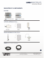
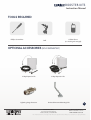
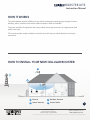
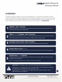
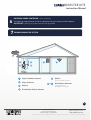
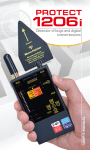
DB-CP
DB-CP
INSTRUCTION MANUAL
BOOSTER KITS
Instruction Manual
TABLE OF CONTENTS
About The Booster Kits
3
Booster Kit Components
5
Tools Required / Optional Equipment
6
How It Works
7
Overview
8
Getting Started
10
Check For Signal Strength
10
Run Coaxial Cable
10
Install The Signal (Outdoor) Antennas
11
Understand The Different Signal (Outdoor) Antennas
12
Install & Connect The Distribution (Indoor) Antennas
13
Understand The Different Distribution (Indoor) Antennas
14
Power Up Your Cellular Booster
17
Check The Cellular Booster Status
18
Manual Gain Control, Uplink & Downlink Adjustments
19
Dip Switch Control For:
• DB-CP DB-CP
20
Troubleshooting
22
Faq
24
NOTE: This manual contains important safety and operating information.
please read and follow the instructions in this manual, failure to do so could be hazardous and result
in damage to your cellular booster.
Canadian Head Office
5005 Jean-Talon Street West #10
Montreal, Quebec, Canada H4P1W7
Phone: 1-800-744-9797
Email: [email protected]
www.cellularbooster.com
The Uniden trademark is owned by Uniden America Corporation and its affiliates is used under license by Signifi Mobile.
BOOSTER KITS
Instruction Manual
INSTALLATION INSTRUCTIONS FOR THE
FOLLOWING CELLULAR BOOSTERS:
• DB-CP model # UNI001 DB-CP
• DB-CP model # UNI002 DB-CP
ABOUT THE BOOSTER KITS
Our goal is to give you a proven solution that ends your frustration with weak and dropped
cellular signals so you can enjoy excellent call quality, more convenience and greater productivity.
DB-CP and DB-CP cellular boosters are Industry Canada and FCC type accepted.
3
Canadian Head Office
5005 Jean-Talon Street West #10
Montreal, Quebec, Canada H4P1W7
Phone: 1-888-744-9797
Email: [email protected]
www.cellularbooster.com
The Uniden trademark is owned by Uniden America Corporation and its affiliates is used under license by Signifi Mobile.
BOOSTER KITS
Instruction Manual
SAFETY AND WARNINGS
• Turn AC power OFF before working on any electrical connections.
• All AC power wiring and coaxial cable wiring must conform to local or national codes.
• The AC line voltage must be within 10% of the voltage specified for the booster.
• A solid copper conductor no less than No. 8 AWG should be connected to ground.
• DO NOT connect a ground wire to a gas supply line.
• DO NOT open the booster. There are no serviceable parts inside.
• Touching internal parts could cause damage from static electrical discharge.
• Opening the base unit DOES VOID THE WARRANTY.
4
Canadian Head Office
5005 Jean-Talon Street West #10
Montreal, Quebec, Canada H4P1W7
Phone: 1-888-744-9797
Email: [email protected]
www.cellularbooster.com
The Uniden trademark is owned by Uniden America Corporation and its affiliates is used under license by Signifi Mobile.
BOOSTER KITS
Instruction Manual
BOOSTER KIT COMPONENTS
BOOSTERS
DB-CP BOOSTER
DB-CP BOOSTER
OUTDOOR ANTENNAS (SIGNAL)
YAGI LPDA
PANEL
POST
INDOOR ANTENNAS (DISTRIBUTIONAL)
WHIP
PANEL
DOME
CABLES (VARIOUS LENGTHS AVAILABLE)
5D-FB
5
SIG 400
Canadian Head Office
5005 Jean-Talon Street West #10
Montreal, Quebec, Canada H4P1W7
Phone: 1-888-744-9797
Email: [email protected]
www.cellularbooster.com
The Uniden trademark is owned by Uniden America Corporation and its affiliates is used under license by Signifi Mobile.
BOOSTER KITS
Instruction Manual
TOOLS REQUIRED
Phillips Screwdriver
Cellular Phone
(to check signal strength)
Drill
OPTIONAL ACCESSORIES (SOLD SEPARATELY)
2 Way Expansion Kit
Lightning Surge Protector
3 Way Expansion Kit
Universal Antenna Mounting Pole
Canadian Head Office
5005 Jean-Talon Street West #10
Montreal, Quebec, Canada H4P1W7
6
Phone: 1-888-744-9797
Email: [email protected]
www.cellularbooster.com
The Uniden trademark is owned by Uniden America Corporation and its affiliates is used under license by Signifi Mobile.
BOOSTER KITS
Instruction Manual
HOW IT WORKS
The cellular booster provides reliable two-way cellular coverage by improving signal strength in homes,
buildings, offices, and other areas where cellular reception is weak or unreliable.
The system amplifies the signal from the nearest cellular tower and re-transmits at a higher power level
within a local area.
This manual provides simple installation instructions that will have your cellular booster kit running in
record time.
HOW TO INSTALL YOUR NEW CELLULAR BOOSTER
3
4
2
1
1 Booster
3 Outdoor Antenna
2 Indoor Antenna
4 Coaxial Cable
Canadian Head Office
5005 Jean-Talon Street West #10
Montreal, Quebec, Canada H4P1W7
7
Phone: 1-888-744-9797
Email: [email protected]
www.cellularbooster.com
The Uniden trademark is owned by Uniden America Corporation and its affiliates is used under license by Signifi Mobile.
BOOSTER KITS
Instruction Manual
OVERVIEW
This guide will help you properly install your cellular booster kit. It is important to read through all of the
installation steps before installing your equipment. Thoroughly read through the instructions, visualize where
all the equipment will need to be installed and do a soft installation before mounting any equipment. If you
do not understand the instructions in full, please contact technical support at: 1-888-744-9797.
1
BOOSTER – SELECT LOCATION
Install the booster in an area that is protected from the weather, properly ventilated and is
away from excessive heat and moisture.
2
SIGNAL (OUTDOOR) ANTENNA - SELECT LOCATION
Mount the signal (outdoor) antenna in an elevated outdoor location so that it points towards
the cellular tower and away from where the inside antenna will be located.
3
OUTDOOR COAXIAL CABLE - SELECT LOCATION
The outdoor coaxial cable is used to connect the signal (outdoor antenna) to the booster.
4
INDOOR COAXIAL CABLE - (IF USED)
The indoor coaxial cable is used to connect the distribution (indoor antenna) to the booster.
5
DISTRIBUTION (INDOOR) ANTENNA
The ideal location for the indoor antenna will be the area of your property where you need
to improve the signal most.
NOTE: The signal strength will be strongest closest to the antenna.
IMPORTANT: The signal (outdoor) antenna should always be separated from the
distribution (indoor) antenna by at least 20 vertical feet or 50 horizontal feet including
the separation of a thick barrier such as a roof or a wall.
Depending on the strength of your outdoor signal, the weaker the signal the less
separation distance is required.
Canadian Head Office
5005 Jean-Talon Street West #10
Montreal, Quebec, Canada H4P1W7
8
Phone: 1-888-744-9797
Email: [email protected]
www.cellularbooster.com
The Uniden trademark is owned by Uniden America Corporation and its affiliates is used under license by Signifi Mobile.
BOOSTER KITS
Instruction Manual
LIGHTNING SURGE PROTECTOR - (SOLD SEPARATELY)
The lightning surge protector connects in between the signal antenna and the booster
6
IMPORTANT: Lightning surge protector must be grounded.
7
COMMISSIONING THE SYSTEM
1
22
4
3
5
3
6
5
7
6
4
1
Signal (outdoor) Antenna
2
Surge Protector
3
Booster
4
Distribution (indoor) Antenna
5
6 &7
Splitter
(if using mutliple antenna)
Distributions Antennas
(optional antennas
for additional coverage)
9
Canadian Head Office
5005 Jean-Talon Street West #10
Montreal, Quebec, Canada H4P1W7
Phone: 1-888-744-9797
Email: [email protected]
www.cellularbooster.com
The Uniden trademark is owned by Uniden America Corporation and its affiliates is used under license by Signifi Mobile.
BOOSTER KITS
Instruction Manual
GETTING STARTED
PLAN THE LAYOUT OF YOUR SYSTEM
Before you get started you will need to plan the layout of your system. This involves checking signal strength
for signals coming from the cell tower, as well as antenna, booster and cable placement.
IDENTIFY THE BEST LOCATION TO INSTALL THE SIGNAL (OUTDOOR) ANTENNA
CHECK FOR SIGNAL STRENGTH
Select a location on the roof of the building to install the signal antenna, by monitoring your cell phone’s
signal strength (signal bars) to find the strongest signal from your carrier’s cell tower.
MARK THE AREA
Mark that area as the installation location for the signal (outdoor) antenna.
IMPORTANT: Confirm that you have at least 20 feet of vertical distance between the
marked antenna location and the location where you will place the distribution (indoor)
antenna. To prevent the system from oscillation (feedback) you want to ensure that there is
enough separation between the distribution and signal antenna or that they are shielded
from each other to ensure the distribution antenna does not send a signal back into
the signal antenna. If you cannot achieve these separations, either choose an alternate
location for the signal (outdoor) antenna or determine if there are natural barriers in the
building construction itself that will attenuate signals between the two antennas so that
oscillation can be prevented.
RUN COAXIAL CABLE
Loosely run the coaxial cable from your outdoor antenna to your booster.
(after you have tested the system you can permanently secure the coaxial cable)
AS YOU ROUTE AND PULL CABLING, FOLLOW THESE GENERAL GUIDELINES
• Bend cables and route them smoothly, and protect the outer skin against any damage.
• Keep horizontal cables straight and fasten them with a tie every three to five feet.
• Bind and fasten vertical cables every six to eight feet.
• Waterproof all outdoor connections with silicone caulking
• Be careful when plugging the connector in so as not to damage the center pins on the connectors.
10
Canadian Head Office
5005 Jean-Talon Street West #10
Montreal, Quebec, Canada H4P1W7
Phone: 1-888-744-9797
Email: [email protected]
www.cellularbooster.com
The Uniden trademark is owned by Uniden America Corporation and its affiliates is used under license by Signifi Mobile.
BOOSTER KITS
Instruction Manual
INSTALL THE SIGNAL (OUTDOOR) ANTENNA
MOUNT THE SIGNAL (OUTDOOR) ANTENNA:
The signal antenna should be located as high as possible (ideal height is 70 feet), in order to capture the best
quality signal from the cellular tower.
Use the mounting hardware in the kit to attach the signal (outdoor) antenna to the building.
CONNECT THE SIGNAL (OUTDOOR) ANTENNA:
Connect the supplied coaxial cable to the antenna. We recommend applying silicone caulking to fully
waterproof the connection.
Attach the cable in such a way that a drip loop is formed (see image below).
Once mounted, connect one end of the coaxial cable to the signal (outdoor) antenna and the other end to
the cellular booster where it is marked “outdoor”.
Drip Loop
CAUTION: please ensure neither you nor the antenna come in contact with electrical power lines.
11
Canadian Head Office
5005 Jean-Talon Street West #10
Montreal, Quebec, Canada H4P1W7
Phone: 1-888-744-9797
Email: [email protected]
www.cellularbooster.com
The Uniden trademark is owned by Uniden America Corporation and its affiliates is used under license by Signifi Mobile.
BOOSTER KITS
Instruction Manual
UNDERSTAND THE DIFFERENT SIGNAL (OUTDOOR)
ANTENNAS
Signal (outdoor) antennas, are needed to capture the signal emanating from your carrier’s cellular tower.
There are different types of signal (outdoor) antennas each designed to meet your specific needs.
The yagi lpda antenna, the post antenna & the panel antenna.
THE YAGI LPDA ANTENNA
The yagi is a very precise directional antenna with a powerful reach. This
antenna should be installed in an elevated position and must be pointed
towards your carrier’s cellular tower.
NOTE: This antenna is not meant to capture signal from multiple carriers.
THE POST ANTENNA
The post is an omni-directional antenna with a 360 degree reach. This
antenna should be installed in an elevated position. It is designed to capture
the signal from multiple carrier towers.
THE PANEL ANTENNA
The panel is a directional antenna with a 120 degree reach and is designed
to capture the signal from multiple carrier towers. This antenna should be
installed in an elevated position and must be pointed towards your carrier’s
cellular tower(s).
12
Canadian Head Office
5005 Jean-Talon Street West #10
Montreal, Quebec, Canada H4P1W7
Phone: 1-888-744-9797
Email: [email protected]
www.cellularbooster.com
The Uniden trademark is owned by Uniden America Corporation and its affiliates is used under license by Signifi Mobile.
BOOSTER KITS
Instruction Manual
LIGHTNING SURGE PROTECTOR - (SOLD SEPARATELY)
The lightning surge protector can be installed indoors or outdoors. When connecting outdoors, install
the lightning surge protector inline between the signal (outdoor) antenna and the coaxial cable. When
connecting indoors, install the lightning surge protector inline between the outdoor coaxial cable and the
booster.
IMPORTANT: Lightning surge protector must be grounded. Connect a ground wire to
the appropriate place on the lightning surge protector and connect the other end to a
verified ground source.
INSTALL THE DISTRIBUTION (INDOOR) ANTENNA
Select the installation location of your supplied distribution (indoor) antenna based on the following:
DOME OMNI DIRECTIONAL ANTENNA
Place in the center of the area where the signal needs to be amplified.
PANEL DIRECTIONAL ANTENNA
Place in the outer perimeter of the area the signal needs to be amplified.
WHIP OMNI DIRECTIONAL ANTENNA
Mount directly to the connector marked “indoor” on the cellular booster.
CONNECTING THE DISTRIBUTION (INDOOR) ANTENNA
DOME OMNI DIRECTIONAL ANTENNA
Connect one end of the coaxial cable to the dome antenna and the other end to the cellular booster where it
is marked “indoor”.
PANEL DIRECTIONAL ANTENNA
Connect one end of the coaxial cable to the panel antenna and the other end to the connector on the cellular
booster where it is marked “indoor”.
WHIP OMNI DIRECTIONAL ANTENNA
Connect the antenna’s end directly to the connector on the cellular booster where it is marked “indoor”.
Canadian Head Office
5005 Jean-Talon Street West #10
Montreal, Quebec, Canada H4P1W7
13
Phone: 1-888-744-9797
Email: [email protected]
www.cellularbooster.com
The Uniden trademark is owned by Uniden America Corporation and its affiliates is used under license by Signifi Mobile.
BOOSTER KITS
Instruction Manual
UNDERSTAND THE DIFFERENT
DISTRIBUTION ANTENNAS
There are several types of distribution (indoor) antennas.
The 3 most common are: the whip antenna, the dome antenna & the panel antenna.
INDOOR ANTENNAS
THE WHIP ANTENNA
The whip antenna is an omni-directional antenna with a 360 degree reach.
It is designed to distribute the signal from the center of the affected area.
Typically it is connected directly to the booster.
THE DOME ANTENNA
The dome antenna is an omni-directional antenna with a 360 degree reach.
It is designed to distribute the signal from the center of the affected area.
Typically it is installed in a false or dropped ceiling.
THE PANEL ANTENNA
The panel is a directional antenna with a 120 degree reach and is designed to
distribute the signal from an perimeter wall or ceiling.
14
Canadian Head Office
5005 Jean-Talon Street West #10
Montreal, Quebec, Canada H4P1W7
Phone: 1-888-744-9797
Email: [email protected]
www.cellularbooster.com
The Uniden trademark is owned by Uniden America Corporation and its affiliates is used under license by Signifi Mobile.
BOOSTER KITS
Instruction Manual
The following diagrams show the reach of each antenna, based on the layout of the space
they are mounted in:
: Booster
: Indoor Panel Antenna
: Splitter
: Indoor Dome Antenna
(2 way cavity splitter shown)
IMAGE 1
IMAGE 2
IMAGE 3
IMAGE 4
IMAGE 1&2) omni directional antennas will provide better coverage for square rooms.
IMAGE 3) directional antennas will provide better coverage in rectangular rooms.
NOTE: installing additional distribution (indoor) antennas may be necessary when the area
that needs coverage is very large or has barriers that block cellular signals such as multi level
homes and buildings.
Canadian Head Office
5005 Jean-Talon Street West #10
Montreal, Quebec, Canada H4P1W7
15
Phone: 1-888-744-9797
Email: [email protected]
www.cellularbooster.com
The Uniden trademark is owned by Uniden America Corporation and its affiliates is used under license by Signifi Mobile.
BOOSTER KITS
Instruction Manual
ANTENNA SEPARATION
IMPORTANT: It is important to leave at least 20 feet of vertical and/or 50 feet of
horizontal separation space between the indoor and outdoor antennas.
Do not connect your cellular device to the cellular booster, as it may damage your cellular
device.
16
Canadian Head Office
5005 Jean-Talon Street West #10
Montreal, Quebec, Canada H4P1W7
Phone: 1-888-744-9797
Email: [email protected]
www.cellularbooster.com
The Uniden trademark is owned by Uniden America Corporation and its affiliates is used under license by Signifi Mobile.
BOOSTER KITS
Instruction Manual
INSTALL YOUR CELLULAR BOOSTER
Install the cellular booster in a location that is properly ventilated and not exposed to excessive heat, moisture and/or direct sunlight. The optimal area would be on a wall located near a power outlet.
It should be mounted in an easily accessible area so it’s easy to perform general maintenance with the coaxial
cable connections, dip switch settings and power adaptor.
Make sure all cables and antennas are securely connected before commissioning the system.
POWER UP YOUR CELLULAR BOOSTER
Once all the below precautions have been taken, power on the cellular booster.
The LED indicator marked power should light up green.
IMPORTANT:
1
Verify that you have left at least 20 feet of vertical and/or 50 feet of horizontal separation space
between the indoor and outdoor antennas.
2
Never point the front of the yagi signal (outdoor) antenna towards the inside of the distribution
(indoor) antenna.
3
Verify that the supplied coaxial cables from both the signal (outdoor) antenna and the distribution
(indoor) antenna are properly connected to the cellular booster before powering it up.
4
Carefully plug in the supplied 110-volt power adaptor into the back of the cellular booster where it
is marked ‘power’ and connect the other end to a power outlet.
WARNING! Using a power supply that is not included in your kit could damage your
equipment and void your warranty.
17
Canadian Head Office
5005 Jean-Talon Street West #10
Montreal, Quebec, Canada H4P1W7
Phone: 1-888-744-9797
Email: [email protected]
www.cellularbooster.com
The Uniden trademark is owned by Uniden America Corporation and its affiliates is used under license by Signifi Mobile.
BOOSTER KITS
Instruction Manual
CHECK THE CELLULAR BOOSTER LED ALARM LIGHTS
Your cellular booster comes equipped with electronic sensors designed to identify cellular signal overload
or oscillation which can hinder signal-boosting performance. Your cellular booster is specially designed
to automatically decrease gain to compensate for these circumstances, the device also has a feature to
automatically shut down in case of excessive oscillation. Improper equipment installation and unusable
signal quality can cause oscillation, this is why it is important to fully understand the LED alarm lights on your
booster, as they will help you identify and solve any potential issues.
The color of the LED indicates the status of the booster system.
TWO TYPES OF LED INDICATORS
1. POWER indicator: Shows whether the cellular booster is on or off.
2. Signal indicators: The color of the LED indicates the status of the booster for each of these frequencies.
There is one alarm LED light for each of the cellular frequency ranges (850 MHz & 1900 MHz).
CHECKING THE SIGNAL STATUS
The signal indicator’s LED will notify you as to whether your cellular booster is experiencing any oscillation
or feedback. The purpose of these LED’s is to allow you to fine tune your booster to achieve optimal signal
quality.
The bullet list below indicates what measure should be taken based on the color of the LED alarm lights.
GREEN: indicates the system is working properly.
ORANGE: the system is experiencing slight oscillation and does require slight adjustment. See next page
for adjustment procedures.
RED: the system is experiencing severe oscillation and may be causing interference with the cellular
provider’s network. Turn the unit off and make adjustments as outlined next page.
OFF: if the LED is off it is likely the system went into oscillation so severe that the auto gain and level
control circuits turned the cellular booster off .
18
Canadian Head Office
5005 Jean-Talon Street West #10
Montreal, Quebec, Canada H4P1W7
Phone: 1-888-744-9797
Email: [email protected]
www.cellularbooster.com
The Uniden trademark is owned by Uniden America Corporation and its affiliates is used under license by Signifi Mobile.
BOOSTER KITS
Instruction Manual
ADJUSTING MANUAL GAIN CONTROL
The Manual Gain Control is used to resolve the issue of oscillation without the need of readjusting your
antennas, in most cases. The manual gain control (MGC) adjusts the overall amplification level (gain) of the
booster.
The MGC allows you to easily reduce the amount of gain (amplification) the booster is emitting. This is done
with a set of dip switches on the side of the booster. There is a series of dip switches to adjust the uplink and
another set to adjust the downlink.
There are 2 sets of dip switches, one is labeLED “high frequency” representing the 1900 mhz range and the
other labeled “low frequency” representing the 850 mhz range. Each set is divided between the downlink
and the uplink. The dip switches, when put into the “on” position will reduce the gain of the booster for the
designated frequency and transmission direction. When the LED alarms are indicating some oscillation you
need to reduce the gain of the downlink and the uplink for the appropriate frequency. Do this gradually in
order to determine the ideal level.
ADJUSTING THE UPLINK
Please follow these procedures for each frequency.
If the alarm LED turns off immediately after commissioning the system, the signal on the uplink is likely too
strong. Take measure to reduce the uplink gain. Continue to increase the gain reduction until the alarm light
changes to green.
ADJUSTING THE DOWNLINK
Once you have fine-tuned the uplink signal, it is time to adjust the downlink. If the alarm LED is green you are
all set. If the alarm LED is orange, you will only need to reduce the gain slightly. If the alarm LED is red, you
will need to greatly reduce the gain. As you implement the gain reductions, the LED alarms should change
from Red or Orange to green.
19
Canadian Head Office
5005 Jean-Talon Street West #10
Montreal, Quebec, Canada H4P1W7
Phone: 1-888-744-9797
Email: [email protected]
www.cellularbooster.com
The Uniden trademark is owned by Uniden America Corporation and its affiliates is used under license by Signifi Mobile.
BOOSTER KITS
Instruction Manual
MGC DIP SWITCH CONTROL FOR
• DB-CP
• DB-CP
The Uniden U2 DB-CP and Uniden U4 DB-CP allows you to manually attenuate the db gain of the device on
both the uplink and downlink on each frequency, the 850 mhz being the “low frequency” and the 1900 mhz
being the “high frequency”. You can adjust the gain in increments of 5 db with a maximum of 15 db.
On the back panel of the device you will see the 8 dip switches labeled 1 through 8 and they are broken into 4
sections. Each section represents 2 dip switches. (see image below)
The Uniden U2 DB-CP and Uniden U4 DB-CP can be reduced by 5, 10, or 15 db. When a dip switch is moved
up to the on position it will implement a reduction for the amount of gain indicated. Therefore, to implement a 5
db reduction, push the dip switch marked 5 up. To implement a 10 db reduction push the dip switch marked 10
up. To implement a 15 db reduction push both dip switches marked 5 and 10 up.
Uniden U2 DB-CP MGC dip switches
Uniden U4 DB-CP MGC dip switches.
20
Canadian Head Office
5005 Jean-Talon Street West #10
Montreal, Quebec, Canada H4P1W7
Phone: 1-888-744-9797
Email: [email protected]
www.cellularbooster.com
The Uniden trademark is owned by Uniden America Corporation and its affiliates is used under license by Signifi Mobile.
BOOSTER KITS
Instruction Manual
The left dip switch in each section will reduce the gain by 10 db and the right dip switch will reduce the gain
by 5 db. In order to initiate a reduction in gain the dip switch needs to be pushed into the “on” position
which is up. So to reduce the gain by 10 db you move the left dip switch in the respective section up, and
leave the right dip switch down in the “off” position.
To reduce the gain by 5 db you do the opposite, meaning you keep the left dip switch down in the “off”
position and push the right dip switch up in the “on” position.
In order to reach the maximum gain reduction of 15 db, you push both dip switches up to the “on” position.
We suggest you always keep the downlink and the uplink dip switches with the same settings, meaning, if
you reduce the gain on the downlink of the maximum of the 1900 mhz frequency by 10 db you should set the
uplink to reduce the gain by 10 db as well.
HERE IS A BREAKDOWN OF THE DIP SWITCH SECTIONS
The first section is labeled dl2 and represents dip switches 1 and 2.
These two dip switches control the downlink of the 1900 mhz frequency.
Dip switch 1 represents a 10 db reduction and dip switch two represents a 5 db reduction.
The second section is labeled ul2 and represents dip switches 3 and 4.
These two dip switches control the uplink of the 1900 mhz frequency.
Dip switch 3 represents a 10 db reduction and dip switch 4 represents a 5 db reduction.
The third section is labeled dl1 and represents dip switches 5 and 6.
These two dip switches control the downlink of the 850 mhz frequency.
Dip switch 5 represents a 10 db reduction and dip switch 6 represents a 5 db reduction.
The fourth section is labeled ul1 and represents dip switches 7 and 8.
These two dip switches control the downlink of the 850 mhz frequency.
Dip switch 7 represents a 10 db reduction and dip switch 8 represents a 5 db reduction.
21
Canadian Head Office
5005 Jean-Talon Street West #10
Montreal, Quebec, Canada H4P1W7
Phone: 1-888-744-9797
Email: [email protected]
www.cellularbooster.com
The Uniden trademark is owned by Uniden America Corporation and its affiliates is used under license by Signifi Mobile.
BOOSTER KITS
Instruction Manual
TROUBLESHOOTING
The booster you have is a dual band booster, essentially it is 2 boosters in 1. One for the 1900 (high) MHz
frequency range and one for the 850 MHz (low) frequency range. The LED alarm lights represent the status
of the booster on each frequency. When the lights are green the device is operating normally meaning that it
is not experiencing any oscillation (feedback) and it is boosting the signal at maximum power. When the LED
lights begin to change color from green to orange to red, it means that that particular frequency is experiencing some oscillation (feedback).
If the oscillation is too excessive the booster will shut down for that particular frequency. The booster will still
work for the other frequency. Carriers use both the 850 MHz and the 1900 MHZ, some towers will transmit
both frequencies and some just one. This is why you may be getting full signal while the booster has shut
down one of the frequencies.
Oscillation is caused when the indoor (distribution) antenna sends a signal back into the outdoor (signal)
antenna. Similar to a PA system, when the microphone gets too close to the speaker it causes feedback. This
will occur if your antennas are too close together, or the indoor antenna is pointed at the outdoor antenna.
Make sure you have adequate separation and some type of shielding between the antennas (usually your roof
or a cement wall is good enough).
IMPORTANT NOTES
The 2 most important things to look for when setting up your system is:
1
A good input signal (the best you can find)
2
Isolating the outdoor (signal) antenna from the indoor (distribution) antennas so they do not
feedback into each other.
By capturing the best input signal you will be able to enjoy the maximum coverage and best quality signal
inside where your distribution antennas are located. The better the input signal, the better the output signal.
In order to find the best input signal, you want to place your outdoor (signal) antenna as high as possible with
the least amount of obstruction between the antenna and the cellular base tower. A clear line of site is ideal.
Isolating the signal from the antennas is done by ensuring that the antennas are not pointing to each other
and by having enough distance or barrier shielding in between them.
Canadian Head Office
5005 Jean-Talon Street West #10
Montreal, Quebec, Canada H4P1W7
22
Phone: 1-888-744-9797
Email: [email protected]
www.cellularbooster.com
The Uniden trademark is owned by Uniden America Corporation and its affiliates is used under license by Signifi Mobile.
BOOSTER KITS
Instruction Manual
The signals travel like rays of sunlight, a directional antenna will send the signal in the direction that it is
pointing. An omni directional antenna will send the signal in every direction around it. So depending on your
equipment is important to be sure that your distribution (indoor) antenna is not sending the signal back into
the outdoor (signal) antenna.
THINGS TO CHECK WHEN EXPERIENCING
WEAK CELLULAR SIGNAL
1
Ensure the signal (outdoor) antenna is pointing in the correct direction and is capturing adequate
signal for the booster.
2
Check all connections on the cable, antennas, and booster.
3
Check cable for bends and or cuts.
4
All LED lights on the booster should be green.
5
Signal (outdoor) antenna and the distribution (indoor) antennas have adequate separation and
are not causing feedback.
23
Canadian Head Office
5005 Jean-Talon Street West #10
Montreal, Quebec, Canada H4P1W7
Phone: 1-888-744-9797
Email: [email protected]
www.cellularbooster.com
The Uniden trademark is owned by Uniden America Corporation and its affiliates is used under license by Signifi Mobile.
BOOSTER KITS
Instruction Manual
FREQUENTLY ASKED QUESTIONS
WHY ARE THE LED LIGHTS TURNING ORANGE, RED OR SHUTTING OFF?
There are certain cases where your system could be experiencing oscillation. This can be attributed to either
the quality of your input signal or having your signal (outdoor) antenna and distribution (indoor) antenna too
close together. Please review the following guidelines to help resolve this issue:
1. Adjust the direction of the signal (outdoor) antenna. If the system is receiving a very high input signal, you
can point your signal (outdoor) antenna away from the cellular tower to reduce the strength of the input
signal and therefore, reduce the oscillation. Alternatively if your system is receiving a very poor quality signal
(weak and unusable signal), you can point your signal (outdoor) antenna more directly towards the cellular
tower to increase the strength of the input signal. (sometimes this may require completely repositioning the
antenna to a location where you can achieve a line of site to the tower)
2. Increase the separation between the signal (outdoor) antenna and the distribution (indoor) antenna. This
can be achieved by increasing the distance between the two antennas or by placing barriers between them,
such as moving the distribution (indoor) antenna to an adjacent room where there would be an additional
wall separating them from the signal (outdoor) antenna.
3. Manual Gain Control. Adjust the gain with the manual gain control function using the dip switches on the
side of the booster. See page 19 for more details
I INSTALLED THE BOOSTER AND MY SIGNAL STRENGTH IS STILL WEAK?
In order to correct a weak signal; essentially you have the options of:
• Adjust the aim of the signal (outdoor) antenna or replace it with a higher gain antenna.
• Move the distribution (indoor) antenna
• Increase the number of distribution (indoor) antennas
• Reducing the attenuation values you chose when setting the manual gain control
I CANNOT MAINTAIN CALLS, MY SIGNAL STRENGTH FLUCTUATES
If you find the booster is working but drops calls or delivers fluctuating signal levels, the most likely cause is
oscillation between the signal and distribution antenna(s).
Determine the status of the cellular booster LED alarms. if so there is insufficient isolation between antennas.
you can either increase the distance between antennas or place barriers between them to attenuate the
signals or adjust the MGC settings.
Canadian Head Office
5005 Jean-Talon Street West #10
Montreal, Quebec, Canada H4P1W7
24
Phone: 1-888-744-9797
Email: [email protected]
www.cellularbooster.com
The Uniden trademark is owned by Uniden America Corporation and its affiliates is used under license by Signifi Mobile.
BOOSTER KITS
Instruction Manual
A second cause for this symptom is poor cable connections. confirm that all cable connections are tight and
secure.
A third cause may be interference from other cellular service providers operating in the same frequency
bands. If their signals are stronger than the cellular signals you want to receive from the cell tower. In this
case the unwanted signal needs to be attenuated either by repositioning or re-aligning the signal (outdoor)
antenna, or by using barriers (buildings, trees, etc) to block the signal.
MY LED’S ARE ALL GREEN BUT MY SIGNAL IS STILL WEAK
MY COVERAGE IS POOR
If you receive a signal where you did not previously... or, if the radius of the service area covered is small...and
your LED’s are all green... the booster is working properly but for some reason the signal is not very strong.
This can be due to weak input signal.
• Adjust your signal (outdoor) antenna to point more accurately at the cellular tower in order to increase the
input signal.
• Check the coaxial cable to ensure there are not any creases or cuts in it. Perhaps the cable was damaged
during installation.
• If the input signal is still low, you may need to install a pre-amplifier to increase the input signal into the
system.
WHY ISN’T MY CELL PHONE INDICATING MORE SIGNAL WITH MORE BARS?
You may not always observe more bars on your signal meter because of the signal spreading out from the
antenna. If your phone has a db meter, 3db is a significant increase of 2 times, 6db is 4 times, and 10db is 10
times. on a four bar phone, one “bar” equals about 10db.
The increase in signal you will see depends upon:
• The level of signal at the signal (outdoor) antenna
• The care of the antenna placement (adequate antenna separation, 30 feet recommended)
• The distance of your phone/device from the distribution (indoor) antenna (signal spreads or diminishes
rapidly with distance.)
25
Canadian Head Office
5005 Jean-Talon Street West #10
Montreal, Quebec, Canada H4P1W7
Phone: 1-888-744-9797
Email: [email protected]
www.cellularbooster.com
The Uniden trademark is owned by Uniden America Corporation and its affiliates is used under license by Signifi Mobile.
BOOSTER KITS
Instruction Manual
NOTES
Model # :
Serial # :
Date Purchased :
Purchased From :
Notes:
26
Canadian Head Office
5005 Jean-Talon Street West #10
Montreal, Quebec, Canada H4P1W7
Phone: 1-888-744-9797
Email: [email protected]
www.cellularbooster.com
The Uniden trademark is owned by Uniden America Corporation and its affiliates is used under license by Signifi Mobile.