1
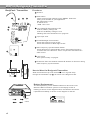
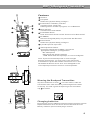
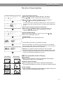
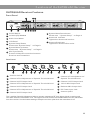
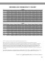
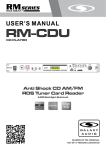
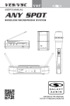
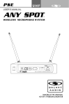
DHTRQUAD
UHF
USER'S MANUAL
®
WIRELESSMICROPHONESYSTEM
ANYSPOT
®
®
DHTRQUAD
UHF Four Channel
Diversity Wireless Receiver
IR
POWER
SYNC
MAKERS OF THE ORIGINAL
HOT SPOT PERSONAL MONITOR
Contents
System Components..........................................1
Rack-Mounting the Receiver...............................2
HH64/HH64SC Handheld Transmitter.................3
MBP64 Bodypack Transmitter.............................4
MBP76 Bodypack Transmitter.............................5
SM-W76 Wireless Shockmount Base..................6
System Setup.....................................................7
Setting up multiple receivers...............................8
Functions of the DHTRQUAD Receiver................9
Troubleshooting.................................................10
Specifications....................................................11
Accessories and Replacement Parts.........................12
DHTRQUAD Frequency Chart....................................13
DHTRQUAD System
DHTRQUAD System
Thank you for purchasing the DHTRQUAD wireless system. For users who need an
advanced UHF wireless system, the DHTRQUAD provides an excellent solution.
With 120 selectable channels, the DHTRQUAD is perfect for applications such as
live shows, broadcast, meetings, & musical instruments. Touch buttons and liquid
crystal displays allow for a quick and simple system setup. The "User Guide"and"
Quick Setting Guide" included in your system will provide all the details you need to
operate the system efficiently.
Frequency Band
Most countries closely regulate the radio frequencies used in the transmission of
wireless information. These regulations state which devises can use which
frequencies, and help to limit the amount of RF (radio frequency) interference in all
wireless communications. The DHTRQUAD offers 120 selectable channels within
either the 584-607MHz (Code D) or 655-679MHz (Code L) frequency ranges.
To facilitate system setup and protect against RF interference, each system comes
with multiple predefined frequency groups and channels. When using a single
receiver/transmitter, the operating frequency will generally not have to be changed.
In an installation with multiple receivers/transmitters, each set must operate on a
separate channel from the others. The group and channel system provides an
optimum frequency spread when using multiple receiver/transmitter systems.
System Components
All systems include:
ANYSPOT
®
®
DHTRQUAD
UHF Four Channel
Diversity Wireless Receiver
IR
POWER
DHTRQUAD Receiver
¼" to ¼" Audio Cable
Power Supply
Two Antennas
Extension Kit
Rack Ears
User Guide
SYNC
O
N
CHANNEL
BATT
O
F
INFRARED
Transmitter Options:
HH64 / HH64SC Handheld Mic/Transmitter
SM-W76 Wireless Shockmount Base
Visit our website
www.galaxyaudio.com
to see all of our great
headset & lavalier
options
LAMP
POWER
BATT
GROUP
CHANNEL
ASC
MBP64
MBP64
Body Pack
Transmitter
MBP76
Body Pack
Transmitter
1
Rack-Mounting the Receiver
Rack-Mounting the Receiver
Maintain a line of sight between
transmitter and antenna.
Panel mount
BNC feed-through
connectors
CN-BNCPM
Antenna
Extension
Cable
EXTBNC
Rack Ears
MREDHTQUAD
ANYSPOT
®
®
DHTRQUAD
UHF Four Channel
Diversity Wireless Receiver
IR
SYNC
POWER
ANT-DISTDC
ANYSPOT
®
Shown with optional
ANT-DISTDC
antenna distributor.
®
UHF ANTENNA DISTRIBUTOR
POWER
ANYSPOT
®
®
DHTRQUAD
UHF Four Channel
Diversity Wireless Receiver
IR
SYNC
POWER
ANYSPOT
®
®
DHTRQUAD
UHF Four Channel
Diversity Wireless Receiver
IR
SYNC
POWER
ANYSPOT
®
®
DHTRQUAD
UHF Four Channel
Diversity Wireless Receiver
ANT-DISTDC Info
IR
SYNC
POWER
ANYSPOT
®
®
DHTRQUAD
UHF Four Channel
Diversity Wireless Receiver
Four DHTRQUAD receivers
IR
SYNC
POWER
The ANT-DISTDC will provide
DC power to operate up to
4 DHTRQUAD Receivers.
ANT-DISTDC
ANT-1
ANTENNA-B
DC IN
ANT-2
ANT-3
M
H
Antenna-B
M
L
H
Channel 4
XLR balanced
SQL
H
Channel 4
XLR balanced
H
Channel 4
XLR balanced
Ten BNC connecting cables (included)
Two BNC connectors (included)
2
H
Channel 4
XLR balanced
H
Channel 4
XLR balanced
ANT-8
ANTENNA-A
Channel 1
XLR balanced
4 in 1 Mix
Unbal output
8 in 1 Mix
XLR balanced
Antenna-B
Channel 1
XLR balanced
4 in 1 Mix
Unbal output
8 in 1 Mix
XLR balanced
Antenna-B
Channel 1
XLR balanced
4 in 1 Mix
Unbal output
8 in 1 Mix
XLR balanced
Antenna-B
Channel 1
XLR balanced
4 in 1 Mix
Unbal output
8 in 1 Mix
XLR balanced
Antenna-B
L
SQL
M
L
SQL
ANT-7
M
L
SQL
H
Channel 4
XLR balanced
ANT-6
L
SQL
M
L
SQL
ANT-5
M
L
H
Channel 4
XLR balanced
12~18
3000mA
L
SQL
M
L
H
Channel 4
XLR balanced
H
Channel 4
XLR balanced
SQL
M
L
SQL
H
Channel 4
XLR balanced
SQL
M
H
Antenna-B
OUTPUT4
600mA
M
L
SQL
M
L
SQL
OUTPUT3
600mA
M
L
SQL
M
H
Antenna-B
H
Channel 4
XLR balanced
M
L
SQL
OUTPUT2
600mA
M
L
SQL
M
H
Antenna-B
OUTPUT1
600mA
ANT-4
H
Channel 4
XLR balanced
L
SQL
1. BNC Cables
2. Power Supply Cable
HH64/HH64SC Handheld Transmitter
Functions:
2
1
GROUP
CHANNEL
BATT
INFRARED
1
Condensor mic
2
Dynamic mic
3
LCD screen
Please See “system setup ” on page 8.
4
Power Switch
5
Microphone Input Sensitivity Control.
Left turn for output level decrease, right
turn for output level increase.
6
IR Port receives infrared beam to synchronize frequencies.
3
4
5
6
Changing Batteries:
GROUP
CHANNEL
BATT
INFRARED
Batteries should be replaced when LCD indicator flashes.
Unscrew the battery cover as shown below. Install
two AA alkaline batteries, while observing correct polarity
indicators in the battery tray.
Expected life for two AA alkaline batteries is 8 hours.
3
MBP64 Bodypack Transmitter
BodyPack Transmitter
1
1
Antenna.
2
Gain Switch.
There are three Gain settings on the MBP64. Select the
setting most suitable to your application.
Mic: Microphone Level
0: Guitar Level
-10dB: Line Level
3
Low Voltage/IR Transmission LED.
LED On: Battery Voltage OK.
LED Off: the Battery Voltage is Low.
Flashing LED: IR transmission is in progress
4
3-pin Input Jack.
5
Power/Backlight Control button
Press and Hold for Power On/Off.
Press and Release for Back-light On/Off.
6
ASC Frequency Synchronization Button.
Press this button to automatically set the Transmitter frequency
to match that of the Receiver. Use in conjunction with Receiver’s
ASC control.
7
LCD screen
See “system setup” on page 8.
8
IR Window Point this window towards IR window on Receiver during
ASC frequency synchronization.
4
3
2
Functions:
LAMP
POWER
5
BATT
6
ASC
7
8
+ +
-
10
How to Wear the Bodypack Transmitter:
9
+ +
-
+ +
-
Slide the transmitter clip onto the belt 9 or run a guitar strap
through the transmitter clip 10 , as shown in the diagram at left.
Battery Replacement :
The life expectancy of two alkaline batteries is about six hours.
When the BATT indication symbol on the display screen is
flashing as shown in the diagram below, the batteries should be
replaced immediately, as shown in the diagram on the left.
BATT
Open
Close
4
GROUP
CHANNEL
MBP76 Bodypack Transmitter
Features
1
1
Antenna.
2
LCD panel.
Please see (System Setup) on Page 7.
3
Power/ASC/ Low Battery Indicator.
Constant Green: Power ON.
Flashing Green: IR ASC in progress, or Low Batteries.
4
Mute Indicator.
Constant Red: Audio Muted.
5
Power/Mute Button.
Push and Hold for Power On/Off. Push once for Mute On/Off.
6
IR Window.
Receives IR signals (ASC) to synchronize with Receiver.
7
Select Button.
Please see (System Setup) on Page 8.
8
3-pin Microphone Input Jack.
9
Gain Adjustment Switch.
Three gain settings are available. Choose the
appropriate setting for your application:
Mic: Microphone
0dB: Guitar with passive pickups
-10dB: Guitar with active pickups, or Line Level Signals.
2
3
5
6
4
7
select
9
8
Note: To prevent accidental power or mute changes
during a performance, you may set the Lock function by
a simultaneous press and release of buttons 5 and 7. This
will disable all buttons and a “lock” icon will appear in the
LCD. Repeat procedure to return to normal operation.
11
10
Wearing the Backpack Transmitter:
Clip the transmitter to a belt 10. For best results, slide the
transmitter down until the belt is pressed against the base
of the clip. Or, slide a guitar strap through the transmitter
clip 11 ,as shown.
Changing batteries:
Open
Close
Expected life for Two Alkaline batteries is approximately 6 hours.
Replace batteries when the Green Power LED and the LCD
Battery Indicator (shown below) begin to blink.
5
SM-W76 Wireless Shockmount Base
1. Adjust the 16 position rotary knob on the rear of the SM-W76 base to change
the frequency. A small flat headed screwdriver can be used.
2. Use the chart to set up the DHTR/TRCR Group & Channel to the frequency
that corresponds to the SM-76 base.
3. Once the Group & Channel of the receiver is set, press the gray button on the
top of the SM-76 base to turn the microphone on.
6
System Setup
Receiver Programming
GROUP
CHANNEL
ANTENNA
MHz
A
B
DISPLAY
EXIT
VOLUME
AUTO
GROUP MANUAL
CONTROL CHANNEL SELECT CHANNEL FREQUENCY MASTER
SELECT
SELECT
SELECT
LIST
2
1
GROUP
CHANNEL
ANTENNA
MHz
A
B
DISPLAY
EXIT
VOLUME
AUTO
GROUP MANUAL
CONTROL CHANNEL SELECT CHANNEL FREQUENCY MASTER
SELECT
SELECT
SELECT
LIST
For best results when operating multiple systems, set all systems to
a single group, then set each system to a unique channel within that
group.
CHANNEL
ANTENNA
MHz
A
B
DISPLAY
EXIT
VOLUME
AUTO
GROUP MANUAL
CONTROL CHANNEL SELECT CHANNEL FREQUENCY MASTER
SELECT
SELECT
SELECT
LIST
3
GROUP
Press “SET”again , “MANUAL CHANNEL SELECT” will display,
press or to choose the appropriate channel.
Auto Frequency Finder function on the Receiver:
3 Choose “AUTO CHANNEL SELECT” by pressing “SET” once,
then press or . Receiver will automatically find a clear
frequency with no interference.
2
GROUP
Group and Channel Selection:
1 Press “SET” button twice, “GROUP SELECT” will display,
press or to choose the appropriate frequency group.
Receiver Volume Setting:
4 The receiver has an electronic volume control. Press
from the normal display (00 to 63)
or
Normal Display:
5 Frequency and Antenna A/B (RF Received).
CHANNEL
ANTENNA
MHz
A
B
Transmitting frequency automatic setup:
DISPLAY
EXIT
VOLUME
AUTO
GROUP MANUAL
CONTROL CHANNEL SELECT CHANNEL FREQUENCY MASTER
SELECT
SELECT
SELECT
LIST
4
GROUP
Place the Transmitter “IR” window to face the Receiver “IR” window.
Then press the “ASC” button on the desired Receiver. The Transmitter
will automatically match the Receiver frequency.
CHANNEL
ANTENNA
MHz
A
B
DISPLAY
EXIT
VOLUME
AUTO
GROUP MANUAL
CONTROL CHANNEL SELECT CHANNEL FREQUENCY MASTER
SELECT
SELECT
SELECT
LIST
5
Handheld
Transmitter
Bodypack
Transmitter
Attention: The distance between the Receiver and Transmitter
IR windows should be less than 0.5m during the ASC IR setup. When
setting up multiple Transmitters/Receivers, activate the ASC function
of only one Transmitter and Receiver at a time.
MBP76 Transmitter Status Display
Battery Status:
1 Battery Status Indicators for both the Handheld and Bodypack
Transmitters feature Four Level Displays.
1
Group and Channel Display:
2 After completing the ASC, both the Handheld and Bodypack
Transmitters will display the Group and Channel numbers selected.
2
Normal Display:
3 Both Handheld and Bodypack Transmitters will display Group and
Channel numbers as well as Battery Status.
3
7
Setting up multiple receivers
4
2
ANYSPOT
®
®
DHTRQUAD
UHF Four Channel
Diversity Wireless Receiver
IR
POWER
SYNC
5
11
1)Power on any pre-existing wireless systems and transmitters except the first DHT system.
2)Power on the first DHT Receiver.
3)The Control and set buttons are on the front of the receiver.
4)Press the set button until the group number flashes on the LCD screen
5)Press the up/down buttons to select group 1.
6Press the set button twice to get to the scan mode.
7)Press the up or down button. The unit will now go into scan mode. You will probably see the RF
meters light up if the scan sees other transmitters.
8)When it stops scanning, it will stop on the clearest frequency, and will be flashing the frequency
on the LCD screen.
9)Press the set button and it will set itself to that frequency. Do not wait to press the set button as
the DHT Receiver will revert back to the original frequency, and the process will need to be restarted
10)If the unit cannot find a good frequency within group 1, start the process again scanning
group 2, if that is also not clear try group 3, and so on till you get a good frequency.
When the DHT Receiver has been set to a clear frequency, use the ASC feature to sync the
receiver frequency to the transmitter.
11)Turn the transmitter on, aim the red infrared window on the transmitter towards the one on
the receiver and press the ASC button on the front of the receiver. The transmitter will sync to
the receivers frequency.
If you have more DHT systems to tune follow the same procedure on each one, always leaving
the previous system transmitter on.
8
Functions of the DHTRQUAD Receiver
DHTRQUAD Receiver Features
Front Panel
ANYSPOT
®
®
DHTRQUAD
UHF Four Channel
Diversity Wireless Receiver
IR
POWER
1
SYNC
On/Off Switch
8 System Menu Down button
Please see “ System Setup” on Page 8
2 Infrared (IR) Window
9 Antenna A Indicator
3 Audio Level Meter
4
Lights when Antenna A is active .
LCD Panel
10 Antenna B Indicator
Lights when Antenna B is active .
5 System Setup Button
Please see “System Setup” on Page 8
6 System Menu Up button
Please see “System Setup” on Page 8
7 ASC Sync Button
Press to initiate IR connection between
Receiver and Transmitter.
Rear Panel
M
H
Antenna-B
M
L
SQL
H
Channel 4
XLR balanced
M
L
SQL
H
Channel 4
XLR balanced
M
L
SQL
H
Channel 4
XLR balanced
L
SQL
Channel 1
XLR balanced
1
Antenna Jack B
2
Channel 4 Fine Adjustment of Squelch Threshold Level
3
Channel 4 XLR Output Jack
4 in 1 Mix
Unbal output
8 in 1 Mix
XLR balanced
Antenna-B
8
Channel 4 Fine Adjustment of
Squelch Threshold Level
9
Channel 1 XLR Output Jack
4
Channel 3 Fine Adjustment of Squelch Threshold Level
10
5
Channel 3 XLR Output Jack
11
Balanced Mix Output Jack
6
Channel 2 Fine Adjustment of Squelch Threshold Level
12
DC Power Input Jack
7
Channel 2 XLR Output Jack
13
Antenna jack A
1/4inch Mix Output Jack
The 3 position Squelch Adjustment helps to prevent extraneous RF from being picked up and turned
into audio when the transmitter is off. The higher level will reduce the useable distance of the transmitter
from the receiver. Use the lowest setting to keep the receiver quiet when the transmitter is off.
9
Troubleshooting
Tips for Improving System Performance
Maintain a line of sight between transmitters and antennas.
Avoid placing the receiver near metal surfaces or any digital equipment (CD players, computers, etc).
Keep the receiver away from the wall and at least 1m from the ground.
Cellular telephones and two-way radios can interfere with the operation of wireless systems.
Do not use these devices in close proximity to the wireless systems.
Troubleshooting
Issue
No sound or faint
sound.
Distortion or
unwanted noise.
Distortion level
increases gradually.
Sound level different
from cabled guitar or
microphone, or when
using different guitars.
10
Indicator Status
Solution
Transmitter LCD off.
Turn on transmitter.
Make sure the batteries are installed
correctly.
Receiver LCD off.
Make sure AC adapter is securely
plugged into electrical outlet and into
DC input connector on rear panel of
receiver.
Receiver indicates RF.
Increase receiver volume.
Make sure Gain adjustment switch on
the transmitter is set correctly (applies
only to MBP76 Bodypack.)
Receiver indicates No RF,
Transmitter LCD is on.
Make sure Transmitter and Receiver
are set to the same frequency.
Make sure Transmitter is in range of
Receiver.
Make sure no large metal objects are
near Transmitter or Receiver.
The battery power indicator
light on LCD flashes.
Change the batteries in transmitter.
Receiver Indicates RF.
Remove nearby sources of RF interference (CD players, computers,
in-ear monitor systems, etc.)
Transmitter power indicator
light flashing on the LCD.
Replace Transmitter batteries.
Adjust Transmitter Gain and Receiver
Volume as necessary.
Specifications
System
Shockmount Transmitter:
Frequency Range: CODE D 584~607 MHz
CODE L 655~679 MHz
Transmitter Output level: 10 dBm
Band: UHF
Operating Range Under Typical
Conditions: 300'
Note: actual range depends on RF signal
absorption, reflection, interference, and
battery characteristics.
Audio Frequency Response (+/-3dB):
60Hz~16kHz
Total Harmonic Distortion (+/-30kHz deviation,
1KHz tone): <1%
Dynamic Range: >90dB A-weighted
Operating Temperature Range:
14ºF to 122ºF (-10º C to +50º C)
Number of Channels: 16
Number of Simultaneous Systems:
4-8 across multiple bands
Carrier Frequency Bandwidth: Code D 584-607 MHz
Code L 655-679 MHz
Operating Range : 150'
Number of Inputs: 1
Type of Connections: XLRF
Indicators: Low battery LED
Frequency Response: 60Hz~16kHz
SNR: 102dB (a)
THD+N: <1%
RF Power: 10 mW
Phantom Power: 4VDC
Power Requirements: 2 “AA” size
alkaline or rechargeable batteries
Power Consumption: 110mA
Weight: 1.55 lbs (without batteries)
Bodypack Transmitter:
Max Audio Input Level:
0 dBV maximum at mic gain position.
+10 dBV maximum at 0 dB gain position.
+20 dBV maximum at 10 dB gain position.
Gain Adjustment Range: 30dB
Input Impedance: 470k
Dimensions: 3.5" x 2.6" x 1"
(89mm H x 65mm W x 24mm D)
Weight: 3.0oz (85 g) (without batteries)
Power Requirements:
2 “AA” Batteries alkaline or rechargeable
batteries
Battery Life:
About 6 hours
Handheld Transmitter:
Receiver:
Audio Output Level (+/-30kHz deviation,
1kHz tone): XLR connector (into 600 load) -12dBV
¼" connector (into 3k load) -18dBV
Output Impedance: XLR connector 200
¼" connector 1k
XLR output: Impedance balanced
Pin1:Ground (cable shield)
Pin2:Audio
Pin3:No Audio
Sensitivity: -93dBm for 30dB
Image Rejection: >90dB
Dimensions: 1.7" x 8.3" x 6.3"
(44mm H x 212mm W x 160mm D)
Weight: 31.75oz (900 g)
Power Requirements:
12-18 V dc at 1000mA, supplied by external
power supply.
Max Audio input level: 0dBV
Dimensions: 9.5" x 2.1" dia.
(242mm x 54mm dia.)
Weight: 10.6oz (300 g) (without batteries)
Power Requirements: 2 “AA” size
alkaline or rechargeable batteries
Battery Life: About 6 hours
11
Accessories and Replacement Parts
Many of these parts and accessories may be found and purchased from the Galaxy Audio
website in either the Galaxy Store (www.galaxyaudio.com/store.php) or in the accessories
tab of each products web page.
AS-EXTBNC - BNC Connector and Cable for front mounting the
antennas on the DHTQUAD.
AS-ANTBNC - Replacement BNC Antenna for use with Galaxy Audio
Wireless Personal Monitors and Wireless Microphones.
WMC-CGR - DC Charger for AS-1500R, HH64, HH64SC, & MBP76.
Charges 2 body packs or handhelds at once.
MC-L - Wireless Microphone Clip
MC-SC - Spring Loaded Microphone Clip
AS-CLIP911R - Replacement Belt Clip for AS-900, AS-1100, MBP52,
& MBP64
AS-CLIP1576 - Replacement Belt Clip for AS-1500 & MBP76
AS-UA12-14.5 - Universal Power Supply for Replacement Power
Supply for AS-900, AS-1100, AS-1500, VES, VSC, ECD, ECM, PSE,
TRC, DHT, DHTQUAD, & CTS. Includes adapters for most other
countries.
PS-13.5-.35.5 - Replacement Power Supply for AS-900, AS-1100,
AS-1500, VES, VSC, ECD, ECM, PSE, TRC & DHT.
ANT-AMPMIC - Antenna Amplifier utilizes phantom power and a low
noise design which covers all UHF frequency points from 500mHz to
900mHz. Metal construction, requires phantom power (9VDC), 50
ohm input/output impedance.
ANT-PDL - Directional antenna used to decrease interference to
other equipment. Frequency range 500-900MHz The UHF wide-band
(500-900 MHZ) directional LPDA (log periodic dipole array) antenna
reduces outside interference while providing increased send/receive
signal range. Each antenna paddle is matched to 50 ohms
impedance with a low-loss BNC connector; 7dBi gain. For permanent
or temporary installation; mounts to 5/8"-27 threads.
12
DHTRQUADFREQUENCYCHART
FCC Consumer Alert for Wireless Microphones (U.S.)
Most users do not need a license to operate this wireless microphone system.
Nevertheless, operating this microphone system without a license is subject to certain
restrictions: the system may not cause harmful interference; it must operate at a low
power level (not in excess of 50 milliwatts); and it has no protection from interference
received from any other device. Purchasers should also be aware that the FCC is
currently evaluating use of wireless microphone systems, and these rules are subject to
change.
For more information, call the FCC at 1-888-CALL-FCC (TTY: 1-888-TELL-FCC) or visit
the FCC's wireless microphone website at www.fcc.gov/cgb/wirelessmicrophones
Please visit galaxyaudio.com for the latest updates
13
THREE YEAR LIMITED WARRANTY
WARRANTY Information can be viewed online at
http://www.galaxyaudio.com/warranty.php
DHTRQUAD
USER'S MANUAL
Specifications in this manual are subject to change without notice.
For the most up to date manual and information
visit www.galaxyaudio.com.
1-800-369-7768
www.galaxyaudio.com
© Copyright Galaxy Audio 2013
Printed in China
V09132013