1
TE120 Series
TE120P/TE121/TE122
User Manual
Release 2.2
Digium, Inc.
445 Jan Davis Drive
Huntsville, AL 35806
United States
Main Number: 1.256.428.6000
Tech Support: 1.256.428.6161
U.S. Toll Free: 1.877.344.4861
Sales: 1.256.428.6262
www.digium.com
www.asterisk.org
www.asterisknow.org
© Digium, Inc. 2007
All rights reserved.
No part of this publication may be copied, distributed, transmitted, transcribed, stored in a
retrieval system, or translated into any human or computer language without the prior written
permission of Digium, Inc.
Digium, Inc. has made every effort to ensure that the instructions contained in this document
are adequate and error free. The manufacturer will, if necessary, explain issues which may
not be covered by this documentation. The manufacturer’s liability for any errors in the
documents is limited to the correction of errors and the aforementioned advisory services.
This document has been prepared for use by professional and properly trained personnel,
and the customer assumes full responsibility when using it.
Adobe and Acrobat are registered trademarks, and Acrobat Reader is a trademark of Adobe
Systems Incorporated.
Asterisk and Digium are registered trademarks and Asterisk Business Edition, AsteriskNOW,
AsteriskGUI, and Asterisk Appliance are trademarks of Digium, Inc.
Any other trademarks mentioned in the document are the property of their respective owners.
Release 2.2
Digium, Inc.
Page 2
Safety Certification and Agency Approvals
Safety:
UL 60950-1:2003, First Edition
CSA C22.2 No. 60950-1-03 1st Ed. April 1, 2003
IEC 60950-1:2001 First Edition
EN 60950
Note: Canada, Finland, Norway, Sweden and the United States of
America require that equipment using this product must be located in a
Restricted Access Location (RAL).
Telecom:
FCC Part 68, ANSI/ITA-968-A, Including Amendment A1 and A2
Industry Canada CS-03
AS/ACIF S016: 2001
AS/ACIF S038: 2001
TBR4 November 1995 as amended by TBR4/A1 December 1997
TBR12 December 1993
TBR13 January 1996
EMC:
EN 55022:1998 Class B and 47 CFR Part 15, Subpart B Class B, Radiated
and Conducted EN 55024:1998 / IEC 61000
Release 2.2
Digium, Inc.
Page 3
Federal Communications Commission Part 68
This equipment complies with Part 68 of the FCC rules and the
requirements adopted by the ACTA. On the back of your TE120 Series
printed circuit board is a label that contains, among other information, a
product identifier in the format US:AAAEQ##TXXXX. If requested, this
number must be provided to the telephone company.
A plug and jack used to connect this equipment to the premises wiring
and telephone network must comply with the applicable FCC Part 68
rules and requirements adopted by the ACTA.
If your TE120 Series card causes harm to the telephone network, the
telephone company may notify you in advance that temporary
discontinuance of service may be required. But if advance notice is not
practical, the telephone company will notify you as soon as possible.
Also, you will be advised of your right to file a complaint with the FCC if
you believe it is necessary.
The telephone company may make changes in its facilities, equipment,
operations or procedures that could affect the operation of the equipment.
If this happens, the telephone company will provide advance notice in
order for you to make necessary modifications to maintain uninterrupted
service.
Release 2.2
Digium, Inc.
Page 4
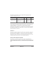
The following information may be required when applying to the
telephone company for service:
Reg. Number
Service Type
US:
DIGDENANTE120P
1.544 Mbps – SF
1.544 Mbps - SF and B8ZS
1.544 Mbps – ESF
1.544 Mbps – ESF and B8ZS
SOC
6.0N
FIC
04DU9-BN
04DU9-DN
04DU9-1KN
04DU9-1SN
USOC
RJ-48C
If you experience problems with the TE120 Series, contact Digium, Inc.
Technical Support +1.256.428.6161 for repair and/or warranty
information. If the equipment is causing harm to the telephone network,
the telephone company may request that you disconnect the equipment
until the problem is resolved.
FCC Part 15
This device complies with part 15 of FCC rules. Operation is subject to
the following two conditions: (1) This device may not cause harmful
interference, and (2) This device must accept any interference received,
including interference that may cause undesired operation.
Industry Canada Compliance Information
The Industry Canada label applied to the product (identified by the
Industry Canada logo or the "IC:" in front of the certification/registration
number) indicates that the Industry Canada technical specifications were
met.
Release 2.2
Digium, Inc.
Page 5
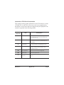
Introduction to TE120 Series Documentation
This manual contains product information for the TE120 Series of cards
(TE120P, TE121, and TE122). Be sure to refer to any supplementary
documents or release notes that were shipped with your equipment. The
manual is organized in the following manner:
Chapter/
Appendix
Title
Description
1
Overview
Identifies your card’s features. This chapter also
covers applications and uses for the TE120 Series
card in the real world.
2
Card Installation
Provides instructions for installing the card in your
PC, acquiring correct drivers, and checking device
compatibility.
3
Configuration
Provides instructions for configuring your card.
4
Troubleshooting
Explains resolutions to common problems and
frequently asked questions pertaining to card
installation and usage.
A
Pin Assignments
Lists the connectors and pin assignments.
B
Specifications
Details card specifications.
C
Glossary and
Acronyms
A list of terms and acronyms used throughout this
manual.
Release 2.2
Digium, Inc.
Page 6
Symbol Definitions
Caution statements indicate a condition where damage to the unit or
its configuration could occur if operational procedures are not
followed. To reduce the risk of damage or injury, follow all steps or
procedures as instructed.
The ESD symbol indicates electrostatic sensitive devices. Observe
precautions for handling devices. Wear a properly grounded
electrostatic discharge (ESD) wrist strap while handling the device.
The Electrical Hazard Symbol indicates a possibility of electrical
shock when operating this unit in certain situations. To reduce the
risk of damage or injury, follow all steps or procedures as
instructed.
Release 2.2
Digium, Inc.
Page 7
Important Safety Instructions
User Cautions
Servicing.
Do not attempt to service this card unless specifically instructed to do
so. Do not attempt to remove the card from your equipment while
power is present. Refer servicing to qualified service personnel.
Water and Moisture.
Do not spill liquids on this unit. Do not operate this equipment in a
wet environment.
Heat.
Do not operate or store this product near heat sources such as
radiators, air ducts, areas subject to direct, intense sunlight, or other
products that produce heat.
Static Electricity.
To reduce the risk of damaging the unit or your equipment, do not
attempt to open the enclosure or gain access to areas where you are
not instructed to do so. Refer servicing to qualified service personnel.
Save these instructions for future reference.
Service Personnel Cautions
Warning.
This card must be used with the PC lid screwed down.
Telecommunications network voltages exist inside the PC!
The PC must be shut down and telecommunications line connection
shall be removed before opening the PC.
Electrical Shock.
To reduce the risk of injury, damage to the unit or your equipment, do
not attempt to touch the modules while they are powered. The case
should be securely closed before power is applied to the unit.
Release 2.2
Digium, Inc.
Page 8
Service Personnel Cautions
Servicing.
Disconnect telecommunications network cable before opening the
cover or removing the card from the motherboard.
Labeling.
For safety reasons, only connect equipment with a
Telecommunications Compliance label. This includes customer
equipment previously labelled Permitted or Certified.
Caution.
Only connect regulatory equipment (approved for use in your specific
country) to the telecommunications network voltage circuit ports.
Caution.
This card is not intended for home use. It must be used in restricted
access locations and installed in UL Listed I.T.E. only.
Release 2.2
Digium, Inc.
Page 9
TABLE OF CONTENTS
Chapter 1
Overview . . . . . . . . . . . . . . . . . . . . . . . . . . . . . . . . . . . . . . . . . . . . . . . 14
Echo-Cancellation . . . . . . . . . . . . . . . . . . . . . . . . . . . . . . . . . . . . . . 17
. . . . . . . . . . . . . . . . . . . . . . . . . . . . . . . . . . . . . . . . . . . . . . . . . . . . 17
What is Asterisk®? . . . . . . . . . . . . . . . . . . . . . . . . . . . . . . . . . . . . . 18
Asterisk as a Switch (PBX) . . . . . . . . . . . . . . . . . . . . . . . . . . . . . . . 18
Asterisk as a Gateway . . . . . . . . . . . . . . . . . . . . . . . . . . . . . . . . . . 18
Asterisk in the Call Center . . . . . . . . . . . . . . . . . . . . . . . . . . . . . . . 19
Asterisk in the Network . . . . . . . . . . . . . . . . . . . . . . . . . . . . . . . . . . 19
Asterisk Everywhere . . . . . . . . . . . . . . . . . . . . . . . . . . . . . . . . . . . . 19
Chapter 2
Card Installation . . . . . . . . . . . . . . . . . . . . . . . . . . . . . . . . . . . . . . . . . 20
Unpacking the Card . . . . . . . . . . . . . . . . . . . . . . . . . . . . . . . . . . . .21
Shipment Inspection . . . . . . . . . . . . . . . . . . . . . . . . . . . . . . . . . . . . 22
Identifying Features . . . . . . . . . . . . . . . . . . . . . . . . . . . . . . . . . . . .22
T1/E1 Selection . . . . . . . . . . . . . . . . . . . . . . . . . . . . . . . . . . . . . . . 22
Slot Compatibility . . . . . . . . . . . . . . . . . . . . . . . . . . . . . . . . . . . . . . 26
Hardware Installation . . . . . . . . . . . . . . . . . . . . . . . . . . . . . . . . . . . 28
Software Installation . . . . . . . . . . . . . . . . . . . . . . . . . . . . . . . . . . . . 29
Installing Asterisk . . . . . . . . . . . . . . . . . . . . . . . . . . . . . . . . . . . . . . 32
Chapter 3
Configuration . . . . . . . . . . . . . . . . . . . . . . . . . . . . . . . . . . . . . . . . . . . . 33
Release 2.2
Digium, Inc.
Page 10
Table Of Contents
Configuring Card Features . . . . . . . . . . . . . . . . . . . . . . . . . . . . . . . 34
Configuring T1/E1 Lines . . . . . . . . . . . . . . . . . . . . . . . . . . . . . . . . .37
T1 Channel Bank . . . . . . . . . . . . . . . . . . . . . . . . . . . . . . . . . . . . . . 40
E1 Channel Bank . . . . . . . . . . . . . . . . . . . . . . . . . . . . . . . . . . . . . . 40
Testing Your Configuration. . . . . . . . . . . . . . . . . . . . . . . . . . . . . . . 45
Chapter 4
Troubleshooting . . . . . . . . . . . . . . . . . . . . . . . . . . . . . . . . . . . . . . . . . 47
Appendix A
Pin Assignments . . . . . . . . . . . . . . . . . . . . . . . . . . . . . . . . . . . . . . . . . 53
Appendix B
Specifications . . . . . . . . . . . . . . . . . . . . . . . . . . . . . . . . . . . . . . . . . . . 54
Appendix C
Glossary and Acronyms . . . . . . . . . . . . . . . . . . . . . . . . . . . . . . . . . . . 56
Release 2.2
Digium, Inc.
Page 11
List of Figures
Figure 1:
Figure 2:
Figure 3:
Figure 4:
Figure 5:
Figure 6:
Figure 7:
Figure 8:
Release 2.2
Sample Legacy Phone Application . . . . . . . . . . . . . .16
Sample IP Phone Application . . . . . . . . . . . . . . . . . . 16
TE120P Card . . . . . . . . . . . . . . . . . . . . . . . . . . . . . . 23
TE121 Card with Echo Cancellation Module . . . . . . 24
TE122 Card with Echo Cancellation Module . . . . . . 25
Motherboard PCI Slots . . . . . . . . . . . . . . . . . . . . . . . 26
Insert the Card . . . . . . . . . . . . . . . . . . . . . . . . . . . . .28
Example dmesg Output . . . . . . . . . . . . . . . . . . . . . . 45
Digium, Inc.
Page 12
List of Tables
Table 1:
Table A-1:
Table B-2:
Release 2.2
Card Identifiers . . . . . . . . . . . . . . . . . . . . . . . . . . . . 30
RJ45 Telco Port Connector . . . . . . . . . . . . . . . . . . . .53
Maximum Power Consumption . . . . . . . . . . . . . . . . .55
Digium, Inc.
Page 13
Chapter 1
Overview
The Digium TE120 Series cards are T1/E1 capable cards that can handle
both voice and data. It supports industry standard protocols, including
Robbed Bit Signaling also known as CAS (Channel Associated
Signaling) and CCS (Common Channel Signaling), E&M (Digital
Emulation), Primary Rate ISDN (PRI), and several data modes (PPP,
HDLC, Cisco HDLC and frame relay). It is capable of running in E1, T1,
or J1 modes.
Designed to be fully compatible with existing software applications and
integrate fully with the Asterisk platform, the TE120 Series cards allow
many advanced call features.
Data Modes:
Cisco HDLC
HDLC
PPP
Multilink PPP
Frame Relay
Release 2.2
Digium, Inc.
Page 14
Chapter 1: Overview
Voice Modes:
PRI CPE and PRI NET
– NI1
– NI2
– EuroISDN
– 4ESS (AT&T)
– 5ESS (Lucent)
– DMS100
E&M
– Wink
– Feature Group B
– Feature Group D
FXO and FXS
– Ground Start
– Loop Start
– Loop Start with Disconnect Detect
The TE120 Series cards can be used to connect your Asterisk machine to
the PSTN world, your channel bank, or even another PBX. This is
accomplished via a T1/E1 interface. The cards allow Asterisk software to
connect to your network, creating a professional telephony environment.
Figure 1 and Figure 2 show examples of the card’s application.
Release 2.2
Digium, Inc.
Page 15
Chapter 1: Overview
Asterisk
Server
T1
TE12X
Internet
Legacy
PBX
Legacy
Phones
Remote offices
Figure 1: Sample Legacy Phone Application
Eth LAN Switch
TE12X
T1
CLEC
Asterisk
Server
IP
Phones
Figure 2: Sample IP Phone Application
Release 2.2
Digium, Inc.
Page 16
Chapter 1: Overview
Echo-Cancellation
Users connecting their TE120 series cards to the PSTN or other devices
are likely to be placing calls that will result, at some point, in an
unbalanced 4-wire/2-wire hybrid. The result of this hybrid is the
reflection of a near-end echo to the calling party. Elimination of this echo
is the responsibility of echo cancellation.
The TE120 series cards, unless otherwise equipped, utilize Asterisk to
perform software-based echo cancellation. Asterisk maintains a number
of open source echo cancelers. These open source echo cancelers provide
a moderate level of echo cancellation, but are not capable of dealing with
higher levels of, or more advanced, echoes.
Digium recommends that those users concerned about echo cancellation
purchase the VPMADT032 hardware echo cancellation module. The
VPMADT032 may be combined with both the TE121 and TE122 cards; it
may not be combined with the TE120P card. The TE121 and TE122 are
offered bundled with the VPMADT032 as, respectively: TE121B,
TE122B.
The VPMADT032 is designed to handle up to 128ms of echo cancellation
across all channels and provides a G.168 compliant and AT&T Labs
certified Toll-Quality echo cancellation solution.
If equipped and not explicitly disabled in zapata.conf, the VPMADT032
will automatically operate and cancel all network echo within its tail
range (1024 taps). Users of TE120P cards, which do not maintain the
capability to support the VPMADT032, may purchase Digium's
commercial HPEC software:
http://www.digium.com/en/products/software/hpec.php
Release 2.2
Digium, Inc.
Page 17
Chapter 1: Overview
What is Asterisk®?
Asterisk is the world’s leading open source telephony engine and tool kit.
Offering flexibility unheard of in the world of proprietary
communications, Asterisk empowers developers and integrators to create
advanced communication solutions...for free. Asterisk® is released as
open source under the GNU General Public License (GPL), and it is
available for download free of charge. Asterisk® is the most popular open
source software available, with the Asterisk Community being the top
influencer in VoIP.
Asterisk as a Switch (PBX)
Asterisk can be configured as the core of an IP or hybrid PBX, switching
calls, managing routes, enabling features, and connecting callers with the
outside world over IP, analog (POTS), and digital (T1/E1) connections.
Asterisk runs on a wide variety of operating systems including Linux,
Mac OS X, OpenBSD, FreeBSD and Sun Solaris and provides all of the
features you would expect from a PBX including many advanced features
that are often associated with high end (and high cost) proprietary PBXs.
Asterisk's architecture is designed for maximum flexibility and supports
Voice over IP in many protocols, and can interoperate with almost all
standards-based telephony equipment using relatively inexpensive
hardware.
Asterisk as a Gateway
It can also be built out as the heart of a media gateway, bridging the
legacy PSTN to the expanding world of IP telephony. Asterisk’s modular
architecture allows it to convert between a wide range of communications
protocols and media codecs.
Release 2.2
Digium, Inc.
Page 18
Chapter 1: Overview
Asterisk as a Feature/Media Server
Need an IVR? Asterisk’s got you covered. How about a conference
bridge? Yep. It’s in there. What about an automated attendant? Asterisk
does that too. How about a replacement for your aging legacy voicemail
system? Can do. Unified messaging? No problem. Need a telephony
interface for your web site? Ok.
Asterisk in the Call Center
Asterisk has been adopted by call centers around the world based on its
flexibility. Call center and contact center developers have built complete
ACD systems based on Asterisk. Asterisk has also added new life to
existing call center solutions by adding remote IP agent capabilities,
advanced skills-based routing, predictive and bulk dialing, and more.
Asterisk in the Network
Internet Telephony Service Providers (ITSPs), competitive local
exchange carriers (CLECS) and even first-tier incumbents have
discovered the power of open source communications with Asterisk.
Feature servers, hosted services clusters, voicemail systems, pre-paid
calling solutions, all based on Asterisk have helped reduce costs and
enabled flexibility.
Asterisk Everywhere
Asterisk has become the basis for thousands of communications
solutions. If you need to communicate, Asterisk is your answer. For more
information on Asterisk visit http://www.asterisk.org or http://
www.digium.com.
Release 2.2
Digium, Inc.
Page 19
Chapter 2
Card Installation
This chapter provides the following information:
Unpacking the Card on page 21
Shipment Inspection on page 22
Identifying Features on page 22
T1/E1 Selection on page 22
Slot Compatibility on page 26
Hardware Installation on page 28
Software Installation on page 29
Installing Asterisk on page 32
Note: The TE120 Series card installation instructions are written so
that they will apply to any card in the series. Examples and card
specific information are included as needed.
Release 2.2
Digium, Inc.
Page 20
Chapter 2: Card Installation
Unpacking the Card
When you unpack your card, carefully inspect it for any damage that may
have occurred in shipment. If damage is suspected, file a claim with the
carrier and contact your reseller from which the card was purchased, or
Digium Technical Support at 1.256.428.6161. Keep the original shipping
container to use for future shipment or proof of damage during shipment.
Note: Only qualified service personnel should install the card. Users
should not attempt to perform this function themselves. The installer
must ensure that the equipment is permanently connected equipment,
pluggable type B or connected to a socket-outlet that has been checked
to ensure that it is reliably earthed in accordance with the National
Electrical Code.
This card is intended for installation in a Restricted Access
Location (RAL) only.
Release 2.2
Digium, Inc.
Page 21
Chapter 2: Card Installation
Shipment Inspection
The following items are included in shipment of the TE120 Series:
A TE120P, TE121, or TE122 card.
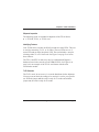
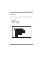
Identifying Features
Your TE120 Series card has one RJ45 port and two status LEDs. The port
is used for connecting T1, E1, or J1 cables. The two LEDs serve as a
status LED and an amber loop-back LED. The card includes a strap for
selecting either T1 or E1 line mode. See Figure 3 on page 23 to locate
these features.
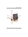
The TE121 and TE122 cards may also be combined with Digium’s
hardware-based echo canceler, model VPMADT032. See Figure 4 on
page 24 for an example of the TE121 card shown with the echo
cancellation module.
T1/E1 Selection
The T1/E1 mode, in most cases, is set at the distributor before shipment.
You may want to check the setting to be certain it is set for your specific
use. With the jumper off, the card is ready for T1 mode and with the
jumper on, the card is ready for E1 mode.
Release 2.2
Digium, Inc.
Page 22
Chapter 2: Card Installation
T1/E1 Jumper
Status LED
Loopback
Mode LED
Port 1
PCI Connector
Figure 3: TE120P Card
Release 2.2
Digium, Inc.
Page 23
Chapter 2: Card Installation
Status LED
VPMADT032
Loopback
Mode LED
Port 1
PCI Express
Connector
Figure 4: TE121 Card with Echo Cancellation Module
Release 2.2
Digium, Inc.
Page 24
Chapter 2: Card Installation
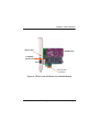
Status LED
VPMADT032
Loopback
Mode LED
Port 1
PCI Connector
Figure 5: TE122 Card with Echo Cancellation Module
Caution.
Only qualified service personnel should continue with
hardware installation and configuration of a TE120 Series
card. Non-qualified personnel should not attempt to perform
these functions.
Release 2.2
Digium, Inc.
Page 25
Chapter 2: Card Installation
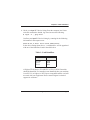
Slot Compatibility
Check the type of card you received to be sure it is compatible with your
PCI slot. To determine which slot you have, identify it by comparing it to
those shown in Figure 6 on page 26.
Slot Number:
0: AGP Pro Slot
1: 64-bit 5.0 volt PCI Slot
2: 64-bit 3.3 volt PCI Slot
3: 32-bit 5.0 volt PCI Slot
4: PCI Express Slot
Slots
0
1
2
3
4
Figure 6: Motherboard PCI Slots
Release 2.2
Digium, Inc.
Page 26
Chapter 2: Card Installation
The TE120 Series and TE122 cards are 32-bit 33MHz cards keyed for
universal 3.3 volt or 5.0 volt operation and works in any PCI 2.2 (or
greater) compliant slot. This means that in the motherboard shown in
Figure 6, the TE120 Series and TE122 cards will fit into Slots 1, 2, or 3
(PCI slots) but will not fit into Slot 0 (AGP slot).
The TE121 card is a PCI Express card. Slot 4, illustrated above, is a 1 lane
(X1) PCI Express compliant slot. The TE121 will work in any PCI
Express compliant slot, including lane lengths X1, X4, X8, and X16. This
means that in the motherboard shown in Figure 6, the TE121 will only fit
into Slot 4. The TE121 can not be used in Slots 0 through 3.
Release 2.2
Digium, Inc.
Page 27
Chapter 2: Card Installation
Hardware Installation
1. Now that you are acquainted with the TE120 Series cards, power
down your computer and unplug it from its power source.
2. Attach a static strap to your wrist and open the case.
3. Check the jumper setting to ensure it matches your equipment
configuration. Setting the jumper with the strap on enables the ports
for E1. Setting the jumper with the strap off enables the ports for T1.
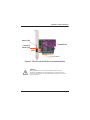
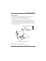
4. Remove the bracket place holder and insert the card into a PCI or PCI
Express slot. See Figure 7.
Figure 7: Insert the Card
5. Replace the cover to your computer.
6. Plug the T1 or E1 equipment cable into the RJ45 port.
Release 2.2
Digium, Inc.
Page 28
Chapter 2: Card Installation
Caution.
This unit must be connected to the Telecommunications
Network in your country using an approved line cord.
Caution.
This unit must be connected only to the appropriate
Telecommunications Network port (as approved for use in your
specific country).
Software Installation
The TE120 Series cards are only supported on a Linux system. Digium,
Inc. recommends Debian, Fedora, and Red Hat. Digium hardware
requires drivers and libraries that are integrated with the Linux kernel.
You can obtain the source code from downloads.digium.com. Detailed
instructions are provided in this section.
To install software for your TE120 Series card, you will need:
Full Linux kernel 2.6 (or later) source code
Development libraries and headers for libncurses (only necessary for
Asterisk 1.2; or for Zaptel 1.4 and Asterisk 1.4).
Development libraries and headers for zlib and openssl.
If you are using the 1.2.x series of Asterisk and Zaptel, you will need
Asterisk 1.2.26 or newer, and Zaptel 1.2.23 or newer. If you are using
the 1.4.x series of Asterisk and Zaptel, you will need Asterisk 1.4.17
or newer and Zaptel 1.4.8 or newer.
Release 2.2
Digium, Inc.
Page 29
Chapter 2: Card Installation
1. Check your lspci PCI device listing. Boot the computer into Linux.
After the machine has loaded, log in and execute the following:
# lspci -n | grep d161
Confirm your lspci PCI device listing by scanning for the following
information in the output screen:
0000:01:00.0 0200: d161:<card identifier>
In the device listing shown above, <card identifier> will be populated
with one of the identifiers listed in the table below.
Table 1: Card Identifiers
Model
TE120P
TE121
TE122
Identifier
0120
8000
8001
A Digium TE120 Series (TE120P/TE121/TE122) ISDN Controller
should be identified. If a controller is not identified, then your machine
is not PCI 2.2 (or higher) or PCI Express compatible and the card will
not work with your equipment. Please contact Digium’s technical
support for assistance.
Release 2.2
Digium, Inc.
Page 30
Chapter 2: Card Installation
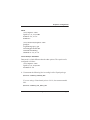
2. Download the latest branch of libpri that matches the branch of Zaptel
and Asterisk which you are using. If you are using the 1.2.x branch,
then download the 1.2.x branch of libpri. Likewise if you are using the
1.4.x branch, then obtain that version of libpri. Libpri is available from
http://downloads.digium.com/pub/telephony/libpri.
3. Expand the downloaded tarballs. Substitute the version of libpri you
are using with the X.X in the command lines below.:
# tar -zxvf libpri-1.X.X.tar.gz
# cd libpri-1.X.X/
# make
# make install
4. Download the latest Zaptel drivers (1.2.23 or later). If you are using
the 1.4 branch of Zaptel, you should use 1.4.8 or later. They are
accessible via http from http://downloads.digium.com/pub/telephony/
zaptel/.
5. Expand the downloaded tarball and install the drivers. Substitute the
version of Zaptel you are using with the XX in the command lines
below.
#tar -zxvf zaptel-1.X.X.tar.gz
#cd zaptel-1.X.X
#make clean
#./configure (applies to 1.4.X only)
#make menuselect (applies to 1.4.X only if you wish
to customize the install)
#make
#make install
Note: If you don’t already have configuration files installed, you can
type make samples to install the default sample configuration files.
Release 2.2
Digium, Inc.
Page 31
Chapter 2: Card Installation
Installing Asterisk
If you wish to use Asterisk with your new hardware, you can follow the
instructions below. If you are using the 1.2.x series of Asterisk and Zaptel,
you will need Asterisk 1.2.26 or newer, and Zaptel 1.2.23 or newer. If you
are using the 1.4.x series of Asterisk and Zaptel, you will need Asterisk
1.4.17 or newer and Zaptel 1.4.8 or newer.
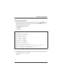
1. Download the latest released version of Asterisk, either 1.2.26 (or
later), or 1.4.17 (or later). Asterisk can be downloaded via http from
http://downloads.digium.com/pub/telephony/asterisk.
2. Expand the downloaded tarballs. Substitute the version of Asterisk
you are using with the X.X in the command lines below.
# tar -zxvf asterisk-1.X.X.tar.gz
# cd asterisk-1.X.X/
# make clean
# ./configure (applies to 1.4.X only)
# make menuselect (appies to 1.4.X only if you wish
to customize the install)
# make
# make install
If the build fails, it may be because you are missing one of the build
dependencies, the kernel source, or development tools. Feel free to
contact your reseller where the card was purchased, or call Digium
Technical Support at 1.256.428.6161 for assistance.
Note: Complete instructions for installing Asterisk are available at
www.asterisk.org.
Release 2.2
Digium, Inc.
Page 32
Chapter 3
Configuration
The TE120 Series cards have a variety of configuration options. This
chapter provides configurations for PRI, channel bank, E&M wink, and
finally, data mode. These sample configurations are provided to assist you
in familiarizing yourself with the flexibility of editing the configuration
files to meet your specific needs. The list of possible configurations is too
expansive to cover in this user manual.
Release 2.2
Digium, Inc.
Page 33
Chapter 3: Configuration
Configuring Card Features
Configure Zapata.conf, which is the layer between zaptel and Asterisk, to
configure the essential card features.
Switchtype:
national:
dms100:
4ess:
5ess:
euroisdn:
ni1:
National ISDN 2 (default)
Nortel DMS100
AT&T 4ESS
Lucent 5ESS
EuroISDN
Old National ISDN 1
Echocancel:
Echo Cancellation is enabled in zapata.conf by preceding the channel
variable with a variable called echocancel and its length in taps (# of
milliseconds multiplied by 8); for example:
echocancel=yes
channel => 1-23
By default, and when setting to "yes," echo cancellation is enabled and set
to 16 ms (128 taps). Echo cancellation is explicitly disabled by setting:
echocancel=no
Digium does not recommend that users set echo cancellation to "no."
Users of open source Asterisk-based echo cancelers also have the
following options:
echocancel=128 (this sets 128 taps or 16ms)
or
echocancel=256 (this sets 256 taps or 32ms)
Release 2.2
Digium, Inc.
Page 34
Chapter 3: Configuration
Users of Digium's HPEC software have the following additional options:
echocancel=512 (this sets 512 taps or 64ms)
or
echocancel=1024 (this sets 1024 taps or 128ms)
Please note that HPEC consumes extremely high amounts of CPU MIPS
that increase as the number of taps are increased. Audio quality issues
may result from choosing a taps length greater than the server's ability to
process the echo in real-time. If audio quality is affected, reduce the taps
length or purchase a TE121 or TE122 and Digium's VPMADT032.
Users of Digium's VPMADT032 hardware echo cancellation module will
have 128ms of echo cancellation performed at all times unless explicitly
disabled by setting the echocancel variable equal to "no."
Release 2.2
Digium, Inc.
Page 35
Chapter 3: Configuration
Signalling:
pri_cpe for CPE side.
pri_net for NET side.
If you have a T1 PRI, add these lines to the following lines of the sample
file.
signalling=pri_cpe
switchtype=national
group=1
context=incoming
channel=>1-23
E1 PRI
signalling=pri_cpe
switchtype=euroisdn
context=incoming
channel=>1-15,17-31
You can also configure a channel bank of phones
signalling=fxo_ks
group=1
context=phones
channel=>1-24
E1 channel bank
signalling=fxo_ks
group=1
context=phones
channel=>1-24
Note: More detailed troubleshooting information is provided on http://
www.asterisk.org.
Release 2.2
Digium, Inc.
Page 36
Chapter 3: Configuration
Configuring T1/E1 Lines
1. Begin by opening the /etc/zaptel.conf. This is where the base
configuration for your hardware is stored. If you did a make samples
during the install, you can read through the commented example and
edit it to your needs. Otherwise, continue following these instructions.
2. Next, configure your T1/E spans in the span definitions. They are in
the following format:
span=<span num>,<timing source>,<line build out
(LBO)>,<framing>,<coding>[,yellow]
<span num>
Since this card only has one span, the <span num> will be 1 if it is the
only Digium digital interface card in your system.
<timing source>
All T1/E1 spans generate a clock signal on their transmit side. The
<timing source> parameter determines whether the clock signal from
the far end of the T1/E1 is used as the master source of clock timing. If
it is, our own clock will synchronise to it. T1/E1's connected directly
or indirectly to a PSTN provider (telco) should generally be the first
choice to sync to. The PSTN will never be a slave to you. You must be
a slave to it.
Release 2.2
Digium, Inc.
Page 37
Chapter 3: Configuration
Choose 1 to make the equipment at the far end of the E1/T1 link the
preferred source of the master clock. Choose 2 to make it the second
choice for the master clock, if the first choice port fails (the far end
dies, a cable breaks, etc.). Choose 3 to make a port the third choice,
and so on. If you have, for instance, 2 ports connected to the PSTN,
mark those as 1 and 2. The number used for each port should be
different.
If you choose 0, the port will never be used as a source of timing. This
is appropriate when you know the far end should always be a slave to
you. If the port is connected to a channel bank, for example, you
should always be its master. Any number of ports can be marked as 0.
Incorrect timing sync may cause clicks/noise in the audio, poor
quality or failed faxes, unreliable modem operation, and dropped calls.
<line build out>
The line build-out (or LBO) is an integer, from the following:
0: 0 db (CSU) / 0-133 feet (DSX-1)
1: 133-266 feet (DSX-1)
2: 266-399 feet (DSX-1)
3: 399-533 feet (DSX-1)
4: 533-655 feet (DSX-1)
5: -7.5db (CSU)
6: -15db (CSU)
7: -22.5db (CSU)
Release 2.2
Digium, Inc.
Page 38
Chapter 3: Configuration
<framing>
d4 or esf for T1
cas, or ccs for E1
<coding>
ami or b8zs for T1
ami or hdb3 for E1
E1 can also have the extra flag CRC4 at the end for CRC4 checking.
[,yellow] (optional)
If the keyword yellow follows, yellow alarm is transmitted when
Asterisk is not running.
The following is a typical setup for a telco in the US:
span=1,1,0,esf,b8zs
In Europe:
span=1,1,0,ccs,hdb3,crc4
3. Next, define the country zone. See the example configuration file for
more details.
defaultzone=us
loadzone=us
4. If you are using Asterisk, you will need to configure it to use your new
hardware. This configuration is located in /etc/asterisk/zapata.conf.
These options are subject to change with future Asterisk versions.
Examples are provided below that may work for you.
Release 2.2
Digium, Inc.
Page 39
Chapter 3: Configuration
First Example: Channel Bank
The Channel Bank in this example has 24 FXS ports. In this
configuration, the zaptel.conf is set for the card to provide timing to the
channel bank and fxoks is set for 24 stations.
Set zapata.conf to mirror the configuration with signalling=fxo_ks and
define it for channels 1-24.
T1 Channel Bank
/etc/zaptel.conf:
span=1,0,0,esf,b8zs
fxoks=1-24
/etc/asterisk/zapata.conf:
group=1
context=channelbank
signalling=fxo_ks
channel=1-24
E1 Channel Bank
/etc/zaptel.conf:
span=1,0,0,ccs,hdb3
fxoks=1-31
/etc/asterisk/zapata.conf:
group=1
context=channelbank
signalling=fxo_ks
channel=1-31
Release 2.2
Digium, Inc.
Page 40
Chapter 3: Configuration
Second Example: E&M Line
To configure a span for E&M, the zaptel.conf must specify the span and
the channel definition, while the zapata.conf specifies the signalling and
incoming dialplan context for a group of channels. In the example below,
the zaptel.conf shows the first span port configured to receive timing,
with no line build-out (LBO), using ESF and B8ZS for framing and
coding. The zapata.conf shows that group 1 has channels 1-24 configured
with featd signalling and processes incoming calls with the "incoming"
dialplan extensions context.
There are many other signalling methods available, though featd is very
common. See the zapata.conf sample configuration file for commented
examples.
/etc/zaptel.conf:
span=1,1,0,esf,b8zs
e&m=1-24
/etc/asterisk/zapata.conf:
group=1
context=incoming
signalling=featd
channel=1-24
Release 2.2
Digium, Inc.
Page 41
Chapter 3: Configuration
Third Example: PRI
By setting the card to take timing in zaptel.conf, you acquire 23 b
channels and voice channels, with channel 24 as the data transport. For
Asterisk, define PRI_CPE so that it is the client side. Define the switch
type you are connecting to as national. There are several options for the
switch type including 5ESS, 4ESS, and NI1. You will then have 23 voice
channels for Asterisk.
PRI T1
/etc/zaptel.conf:
span=1,1,0,esf,b8zs
bchan=1-23
dchan=24
/etc/asterisk/zapata.conf
group=1
signalling=pri_cpe
switchtype=national
context=incoming
channel=1-23
Release 2.2
Digium, Inc.
Page 42
Chapter 3: Configuration
PRI E1
/etc/zaptel.conf:
span=1,1,0,ccs,hdb3
bchan=1-15,17-31
dchan=16
/etc/asterisk/zapata.conf
group=1
signalling=pri_cpe
switchtype=euroisdn
context=incoming
channel=1-15,17-31
Fourth Example: Data Mode
Data mode is a little different than the other options. The zaptel.conf is
configured as follows:
/etc/zaptel.conf
span=1,0,0,esf,b8zs
nethdlc=1-24
1. Uncomment the following line in zconfig.h of the Zaptel package:
#define CONFIG_ZAPATA_NET
If you are using a Linux kernel prior to 2.4.19, also uncomment this
line:
#define CONFIG_OLD_HDLC_API
Release 2.2
Digium, Inc.
Page 43
Chapter 3: Configuration
Build the data tools for Zaptel by executing:
make data; make sethdlc-new
Or, for kernels prior to 2.4.19
make data; make sethdlc
make install
2. Load and configure your driver:
modprobe wcte12xp
ztcfg
3. Use sethdlc to bring up the interface:
sethdlc hdlc0 cisco
-or- for old style (make sethdlc instead of sethdlc-new) use:
sethdlc hdlc0 mode cisco
4. Assign the interface an address:
ifconfig hdlc0 192.168.0.1 netmask 255.255.255.0
5. The interface may be addressed as any other networking interface
(i.e., eth0) in Linux.
Release 2.2
Digium, Inc.
Page 44
Chapter 3: Configuration
Testing Your Configuration.
1. Load Zaptel drivers into the kernel using the program modprobe. The
appropriate driver for the TE120 Series cards is wcte12xp. Use the
following modprobe command:
# modprobe wcte12xp
# ztcfg -vv
# dmesg
ACPI: PCI interrupt 0000:01:00.0[A] -> GSI 21 (level, low) -> IRQ
209
PCI Config reg is 02900117
wcte120p: New Reg: fe590000!
Detected REG0: 00000100
Detected REG1: 00007849
Detected REG2: 0000001d
(pre) Reg fc is 50000027
Detected REG0: 0000ffff
(post) Reg fc is 50000024
Detected REG2: 0000ffff
wcte120p: reg is a04c0004
TE120P: FALC version: 00000000
TE120P: Setting up global serial parameters for T1 FALC V1.2
TE120P: Successfully initialized serial bus for card
Found a Wildcard TE: Wildcard TE120P
Figure 8: Example dmesg Output
2. Run zttool from the command line and see if the span turns green for
each span you have connected.
zttool
Release 2.2
Digium, Inc.
Page 45
Chapter 3: Configuration
3. Execute the following Asterisk command to see if the span came up
successfully.
asterisk
asterisk -vvvr
Note: More detailed troubleshooting information is provided on http://
www.asterisk.org.
Release 2.2
Digium, Inc.
Page 46
Chapter 4
Troubleshooting
This chapter provides frequently asked questions as identified from
Digium Technical Support and possible resolutions. Multiple resources
are available to obtain more information about Asterisk and Digium
products. These resources are listed on page 52.
What do the Status LED colors indicate?
Green - Card is in-sync with the far end.
Yellow - Card is synchronizing or is receiving a red alarm from the far
end. Use a software tool such as zttool to get a textual description of
the state of the card.
Red - Card is not seeing far end, circuit is not up, or cable is bad.
I can't receive DID calls even though I have it enabled in
extensions.conf.
Your telco might be sending calls with a method you are not expecting.
1. Check the method being used by attempting the following in your line
context:
_x.,1,NoOp(My DID Matches as ${EXTEN}
Release 2.2
Digium, Inc.
Page 47
Chapter 4: Troubleshooting
2. Then type reload in the Asterisk console and call in. You should see
the DID come in on your T1/E1 line.
My D Channel seems to go up and down.
Check to be sure you have set your timing parameters correctly. Also
check the common causes of problems for a T1. See the Common Fixes
for all cards, page 50.
I have trouble dialing out. It seems that one type of dialing works
(local, long distance, international) but another does not.
Check your pridialplan variable and be sure that you are dialing using the
method your telco is expecting.
I am having trouble receiving access code information over E&M.
Try the other types of E&M (featd, featb, etc.) to match the method your
telco is using to stream information.
I am having issues with my PRI. How can I see the messages coming
across my D channel?
Enter the following command:
PRI debug span X
where x is the port from which you are connected. This command will
show you the PRI messages coming across your D channel for that
message.
Release 2.2
Digium, Inc.
Page 48
Chapter 4: Troubleshooting
I am still having problems and the telco tells me it is my equipment.
The first thing to do in this situation is to test your equipment.
1. Connect a loopback plug. (A loopback plug has pin 1 going to pin 4
and pin 2 going to pin 5.) Insert the plug into the span and wait for its
LED to turn green.
2. Stop Asterisk and edit zaptel.conf by removing the lines defined for
your card and replacing them with the following:
span=>1,0,0,esf,b8zs
clear=1-24
Or if you have an E1 span:
span=> 1,0,0,ccs,hdb3
clear=1-31
Release 2.2
Digium, Inc.
Page 49
Chapter 4: Troubleshooting
3. Navigate to your zaptel source directory and type:
make tests
Followed by:
./patlooptest /dev/zap/1 60
The first argument in the patlooptest command is the device for the
channel number you want to test. You should always test the first
channel of a span. The second argument is the duration in seconds to
run the test.
This runs a pattern looptest for 60 seconds. If you receive any failures,
it is possible you have a bad card and will need to call Digium
Technical Support at 1.256.428.6161
Common Fixes for all cards
1. Check for shared interrupts by entering the following:
cat /proc/interrupts
and
lspci -vb
If a conflict exists, try moving the card to another PCI slot.
Release 2.2
Digium, Inc.
Page 50
Chapter 4: Troubleshooting
2. Check to see if X windows is running by entering the following:
ps aux|grep X
If X windows is running, stop the application since it may cause a
conflict with Asterisk.
3. Check to see if your IDE hard drives are running with DMA levels set.
Advanced users can perform an hdparm on your hard drive interface.
Use hdparm with caution as the man page states that hard drive
corruption can occur when using incorrect settings. Please
review the man page for hdparm and make sure you understand
the risks before using this tool.
Check the current mode using this command:
hdparm -vi /dev/[IDE Device]
Use this command to set the drives into UDMA2 mode:
hdparm -d 1 -X udma2 -c 3 /dev/[IDE Device]
If you are still having problems, contact your reseller from which the
card was purchased, or Digium Technical Support at 1.256.428.6161.
Release 2.2
Digium, Inc.
Page 51
Chapter 4: Troubleshooting
How can I enable more features?
To view all of the options available to add to your dial plan, type the
following command from within Asterisk:
show applications
Digium also offers services to help configure and add features you might
need. Contact Digium Technical Support at 1.256.428.6161 for more
information.
Where can I ask even more questions?
There are several places to inquire for more information about Asterisk
Digium products:
1. Digium Technical Support at 1.256.428.6161 is available 7am-7pm
Central Time (GMT -6), Monday - Friday.
2. Asterisk users mailing list (asterisk.org/lists.digium.com).
3. IRC channel #asterisk on (irc.freenode.net).
Subscription Services Program
Digium is dedicated to supporting your Asterisk system by offering full
technical support through our Subscription Services Program. Through
this program, you can be at ease knowing that your business will always
have access to the Asterisk experts. Pricing on Subscription Services may
be obtained from your nearest reseller or you may call Digium Sales for
referral to your nearest reseller at +1.256.428.6000 or e-mail
[email protected].
Release 2.2
Digium, Inc.
Page 52
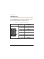
Appendix A
Pin Assignments
The communication port on the TE120 Series card bracket is an 8-pin
RJ45 port. The pin assignments are identified in Table A-1.
Table A-1: RJ45 Telco Port Connector
Pin 1
Pin 8
Release 2.2
Pin
Description
1
Rx
2
Rx
3
Not used
4
Tx
5
Tx
6
Not used
7
Not used
8
Not used
Digium, Inc.
Page 53
Appendix B
Specifications
This appendix provides specifications, required environmental
conditions, and maximum power consumption for the TE120P
card.
Physical.
Size:
Weight:
4.82” × 2.175” × 0.63” (12.2 x 5.5 x 1.6 cm)
PCB size, does not include the PCI bracket
2 oz (57g)
Interfaces.
Local Loop Access: E1, T1, J1, PRI; RJ45
PCI Bus (TE120P and TE122): 3.3V or 5V bus slot, half-length slot
minimum size, 33MHz minimum bus speed, compliant with PCI
2.2 or greater.
(TE121) - PCI-E X1, compliant with PCI-E X1 1.0 or greater.
Environment.
Temperature: 0 to 50° C (32 to 122° F) operation
-20 to 70° C (4 to 158° F) storage
Humidity: 10 to 90% non-condensing
Release 2.2
Digium, Inc.
Page 54
Appendix B: Specifications
Hardware and Software Requirements.
800-Mhz Pentium III or better
64MB RAM
Available PCI Slot (as described previously)
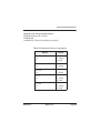
Table B-2: Maximum Power Consumption
Model
Release 2.2
Power
TE120P
3.3V
5V
1.5 Watts
0.1Watt
TE121
3.3V
2.0 Watts
TE121B
3.3V
3.0 Watts
TE122
3.3V
5V
1.5 Watts
0.1Watt
TE122B
3.3V
5V
2.5 Watts
0.1Watt
Digium, Inc.
Page 55
Appendix C
Glossary and Acronyms
ANSI
American National Standards Institute
An organization which proposes and establishes standards for
international communications.
asynchronous
Not synchronized; not timed to an outside clock source. Transmission is
controlled by start bits at the beginning and stop bits at the end of each
character. Asynchronous communications are often found in internet
access and remote office applications.
attenuation
The dissipation of a transmitted signal’s power as it travels over a wire.
bandwidth
The capacity to carry traffic. Higher bandwidth indicates the ability to
transfer more data in a given time period.
bit
The smallest element of information in a digital system. A bit can be
either a zero or a one.
bps
bits per second
A measurement of transmission speed across a data connection.
Release 2.2
Digium, Inc.
Page 56
Appendix C: Glossary and Acronyms
broadband
Broadband transmission shares the bandwidth of a particular medium
(copper or fiber optic) to integrate multiple signals. The channels take up
different frequencies on the cable, integrating voice, data, and video over
one line.
channel
A generic term for an individual data stream. Service providers can use
multiplexing techniques to transmit multiple channels over a common
medium.
Cat5
Category of Performance for wiring and cabling. Cat 5 cabling support
applications up to 100 MHz.
Cat5E
Category of Performance for wiring and cabling. Category 5 Enhanced
wiring supports signal rates up to 100 MHz but adheres to stricter quality
specifications.
CLEC
competitive local exchange carrier
A term for telephone companies established after the
Telecommunications Act of 1996 deregulated the LECs. CLECs compete
with ILECs to offer local service. See also LEC and ILEC.
Release 2.2
Digium, Inc.
Page 57
Appendix C: Glossary and Acronyms
CO
central office
The CO houses local switching equipment. All local access lines in a
particular geographic area terminate at this facility (which is usually
owned and operated by an ILEC).
CPE
customer premises equipment
Terminal equipment which is connected to the telecommunications
network and which resides within the home or office of the customer. This
includes telephones, modems, terminals, routers, and television set-top
boxes.
DS0
Digital Signal, Level 0
A voice grade channel of 64 Kbps. The worldwide standard speed for
digitizing voice conversation using PCM (Pulse Code Modulation).
DS1
Digital Signal, Level 1
1.544 Mbps in North America (T1) and Japan (J1) -up to 24 voice
channels (DS0s), 2.048 Mbps in Europe (E1) - up to 32 voice channels
(DS0s). DS1/T1/E1 lines are part of the PSTN.
DS3
Digital Signal, Level 3
T3 in North America and Japan, E3 in Europe. Up to 672 voice channels
(DS0s). DS3/T3/E3 lines are not part of the PSTN
DTMF
Dual Tone Multi-Frequency
Push-button or touch tone dialing.
Release 2.2
Digium, Inc.
Page 58
Appendix C: Glossary and Acronyms
E1
The European equivalent of North American T1, transmits data at 2.048
Mbps, up to 32 voice channels (DS0s).
E3
The European equivalent of North American T3, transmits data at 34.368
Mbps, up to 512 voice channels (DS0s). Equivalent to 16 E1 lines.
EMI
Electromagnetic Interference
Unwanted electrical noise present on a power line
full duplex
Data transmission in two directions simultaneously.
G.711
The International Telecommunications Union recommendation for an
algorithm designed to transmit and receive mulaw PCM voice and A-law
at digital bit rate 64 Kbps. This algorithm is used for digital telephone sets
on digital PBX.
G.729
An International Telecommunications Union standard for voice
algorithm.
H.323
An International Telecommunications Union standard for multimedia
communications over packet-based networks.
Release 2.2
Digium, Inc.
Page 59
Appendix C: Glossary and Acronyms
IAX
Inter-Asterisk eXchange
A VoIP protocol used by Asterisk. It is used to enable VoIP connections
between Asterisk servers, and between servers and clients that also use
the IAX protocol.
iLBC
internet Low Bitrate Codec
A free speech codec used for voice over IP. It is designed for narrow band
speech with a payload bitrate of 13.33 kbps (frame length = 30ms) and
15.2 kbps (frame length = 20 ms).
ILEC
incumbent local exchange carrier
The LECs that were the original carriers in the market prior to the entry of
competition and therefore have the dominant position in the market.
interface
A point of contact between two systems, networks, or devices.
ISO
International Standards Organization
LED
light-emitting diode
Linux
A robust, feature-packed open source operating system based on Unix
that remains freely available on the internet. It boasts dependability and
offers a wide range of compatibility with hardware and software. Asterisk
is supported exclusively on Linux.
Release 2.2
Digium, Inc.
Page 60
Appendix C: Glossary and Acronyms
loopback
A state in which the transmit signal is reversed back as the receive signal,
typically by a far end network element.
MGCP
Media Gateway Control Protocol
multiplexing
Transmitting multiple signals over a single line or channel. FDM
(frequency division multiplexing) and TDM (time division multiplexing)
are the two most common methods. FDM separates signals by dividing
the data onto different carrier frequencies, and TDM separates signals by
interleaving bits one after the other.
MUX
multiplexer
A device which transmits multiple signals over a single communications
line or channel. See multiplexing.
PBX
private branch exchange
A smaller version of a phone company’s large central switching office.
Example: Asterisk.
PCI
peripheral component interconnect
A standard bus used in most computers to connect peripheral devices.
POP
point of presence
The physical connection point between a network and a telephone
network. A POP is usually a network node serving as the equivalent of a
CO to a network service provider or an interexchange carrier.
Release 2.2
Digium, Inc.
Page 61
Appendix C: Glossary and Acronyms
POTS
plain old telephone service
Standard phone service over the public switched telephone network
(PSTN). This service provides analog bandwidth of less than 4 kHz.
PPP
point-to-point protocol
Type of communications link that connects a single device to another
single device, such as a remote terminal to a host computer.
PSTN
public switched telephone network
The public switched telephone network (PSTN) is the network of the
world's public circuit-switched telephone networks. Originally a network
of fixed-line analog telephone systems, the PSTN is now almost entirely
digital, and now includes mobile as well as fixed telephones.
QoS
quality of service
A measure of telephone service, as specified by the Public Service
Commission.
RJ11
A six-pin jack typically used for connecting telephones, modems, and fax
machines in residential and business settings to PBX or the local
telephone CO.
SIP
Session Initiation Protocol
An IETF standard for setting up sessions between one or more clients. It
is currently the leading signaling protocol for Voice over IP, gradually
replacing H.323.
Release 2.2
Digium, Inc.
Page 62
Appendix C: Glossary and Acronyms
T1
A dedicated digital carrier facility which transmits up to 24 voice
channels (DS0s) and transmits data at 1.544 Mbps. Commonly used to
carry traffic to and from private business networks and ISPs.
T3
A dedicated digital carrier facility which consists of 28 T1 lines and
transmits data at 44.736 Mbps. Equivalent to 672 voice channels (DS0s).
TDM
time division multiplexer
A device that supports simultaneous transmission of multiple data streams
into a single high-speed data stream. TDM separates signals by
interleaving bits one after the other.
telco
A generic name which refers to the telephone companies throughout the
world, including RBOCs, LECs, and PTTs.
tip and ring
The standard termination on the two conductors of a telephone circuit;
named after the physical appearance of the contact areas on the jack plug.
twisted pair
Two copper wires commonly used for telephony and data
communications. The wires are wrapped loosely around each other to
minimize radio frequency interference or interference from other pairs in
the same bundle.
Release 2.2
Digium, Inc.
Page 63
Appendix C: Glossary and Acronyms
V
volts
VoIP
Voice over IP
Technology used for transmitting voice traffic over a data network using
the Internet Protocol.
Zaptel (Zap)
Zapata Telephony Project dedicated to implementing a reasonable and
affordable Computer Telephony platform into the world marketplace.
Release 2.2
Digium, Inc.
Page 64