1
UTV500CC User’s Manual
www.UTVsFactory.com
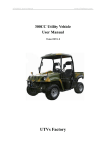
500CC Utility Vehicle
User Manual
Vision 2007-1.0
UTVs Factory
UTV500CC User’s Manual
www.UTVsFactory.com
Table of contents
I、
II、
Notices
Technical parameters
III、 Placement drawing for whole vehicle
IV、 Inspection before driving
V、
Driving operation
VI、 Running-in of new vehicle
VII、 Maintenance and repair
VIII、Trouble diagnosis and elimination
IX、
Screwing moment of important bolts
X、
Specification and dosage table for fuel, Lubricating oil and brake liquid
XI、
Circuit diagram
2
UTV500CC User’s Manual
www.UTVsFactory.com
I、
、Notes
1. Please read this operating instruction carefully before using this vehicle, and
drive, check and repair it by the requirement in this manual to keep vehicle at good
technical status and prolong its using lifetime.
2. Initial running for 1000km of vehicle is period. In this period, it is necessary to
accord with the regulation of period(see the chapter—for new vehicle). After period
expires, it is necessary to make vehicle maintenance by regulation.
3. Quality warrant term of vehicle: in normal using situation, it is three months or
3000km mileage after buying this vehicle, if one of these two exceeds regulated value,
quality warrant term expires. In quality warrant term, for those malfunctions caused by
design, manufacture, assembly quality which influence your usage, our company will
repair them freely.
4. Damaged parts in following items could not be repaired freely, they should be
paid, please forgive:
(1) Damages caused by wrong usage, maintenance and storage which do not accord
with this operating instruction.
(2) Damages caused by force majeure, chemical substance, bad substance or other
natural disasters.
(3) Consumed parts in normal usage, such as: bulbs, fuse(pipe), air filter core,
engine oil filter core, gasoline filter core, brake friction sheet(drum), spark plug, tyre,
transmission belt, appliqué, rubber parts, standard fastening parts, lubricating oil(grease),
brake liquid and so on.
(4) Damages caused by improper assembly or repair, such as self-dismantling or
changing this vehicle without approval of our company and chartered sale(repair) store,
or sending chartered sale(repair) store for repair which is not appointed by our company.
(5) Vehicles which could not provide warrant card or vehicle purchase credential.
(6) Malfunctions caused by using other parts or accessories which are not provided
by our company.
(7) Various overhead expenses caused by repairing vehicle(such as telephone fee,
vehicle fare, freightage, work missing fee, repair fee out of repair store appointed by our
company).
(8) Abnormal abrasions and damages caused by wrong using gasoline, lubricating
oil and brake liquid.
(9) Feeling phenomenon which could not influence mechanical performance, such
3
UTV500CC User’s Manual
www.UTVsFactory.com
as: noise, vibration, heat and so on.
(10) Damages caused by that you do not check and maintain vehicle periodically by
our requirements.
II、
、Technical parameters
(I)、Common technical data
1、Mass parameters(kg)
Mass of whole equipments(not including driver): 590Kg
Front shaft: 260Kg
Rear shaft : 330Kg
2、Dimension parameter(mm)
Total length×total width×total height:2600×1280×1960
Minimal clearance apart from ground: 210
Wheelbase: 1730
Tread: front wheel:1036
rear wheel: 1040
Approach angle(°):47
Removed angle(°):82
(II)、Using data
1、High running speed(km/h):H gear : 70
2、Small steering semi-diameter(m): 4.65
3、Brake performance (No-load brake distance m).
When V0=30km/h:4.
When V0=40km/h:5.5
When V0=50km/h:9
4、0—50Km/h accelerating time(H):7.9”
0—50Km/h accelerating time(L):8.4”
5、Oil consumption for 100 kilometers (L):10
6、Exhaust:Reach Euro II exhaust standard.
7、Loading capacity:: 300Kg
(III)、Engine
Type:CF188
Form:single cylinder, four-stroke, water cooling, 4 valves, top camshaft, single equal
shaft, Carburetor type.
Cylinder diameter(mm): 87.5
Travel(mm): 82
4
UTV500CC User’s Manual
www.UTVsFactory.com
Engine displacement: 493
Compressed ratio: 10.2:1
Maximal power (kw/r/min): 24/6500 (EEC model less than 15kw)
Maximal torque(N·m/r/min): 38.8/5500 (EEC model: 30N.M/4500r/min)
Lowest fuel consuming rate (g/Kw·h): 340
Idling speed (r/min): 1300±100%
Start type: electronic start
Ignition type: non-touch CDI DC start
Plug type: DPR7EA-9(NGK)
Magneto type: ever-mag DC motor, ex-rotor flywheel type.
Lubricating oil category: SAE 15W—40/SF
Engraved position of factory number: Upper surface on rear part of left crankcase
Ignition ahead angle(°/r/min): 10/1500
32/1500
Lubricating type: Pressure and splash lubricating type
Engine oil pump type: TOTOR type
Engine oil filter type: whole filtering with paper element
Carburetor style: vacuum film
Air filter: Sponge element filtering
Fuel type: higher class than RQ-93
Transmission: V-belt with teeth on, auto stepless gear change, plus gear change cam
with change gear transmission.
Gear change type: gear lever with hand
Clutch type: wet, hoof centrifugal type
Primary speed change ratio (stepless speed change): 0.703—2.88
Speed change ratio:
Total speed reduce ratio:
H Gear:3.514
2.47—10.12
L Gear: 5.857
4.12—16.87
R Gear: 3.828
2.69—11.02
Cooling style: Closed cooling fluid circulating.
Cooling fluid type: antifreeze with prevent rust
Out dimension: 610 x 568 x 519
Net weight: 70kg
Output type: front and rear shaft output
Shaft running direction: clockwise (from back of engine).
(IV)、Chassis
1. Clutch and transmission: wet hoof auto-centrifugal clutch. V belt, auto-stepless
transmission plus gear change cam transmission.
5
UTV500CC User’s Manual
www.UTVsFactory.com
2. Main Driver:
Main driver: Tapered arc gear transmission,transmission rate: 33/9
3. Driving type: 4×4 front and rear wheels drive; Rear wheel is the normal
drive. Front wheel can be took off the driving. They are all the shaft
transmission。
4. Suspension:
Front suspension: swing arm type independent suspension.
Rear suspension: co-length double swing arm independent suspension, two
shock absorbers on each side of rear wheel.
5. Front Wheel alignment parameter:
Front wheel extroversion angle: 0° ±1°
Main pin inner obliquity:
11°50’ ±3°
Main pin back obliquity:
4°±1°
Front toe-in: -3—3mm
6. Tyre:
Front wheel: Front wheel type 25×8.00—12 Air inflating pressure:
250Kpa
Rear wheel:Tyre type 25×10.00—12
Air inflating pressure:
300Kpa
7. Steering system:
Adopt gear rack type redirector, total circle number of steering plate:3.75;
total swing angle of steering wheel:75°.
Maximum turning left: 37.5°.
Maximum turning right: 37.5°.
8. Brake:
Brakes adopt front and rear placement dual-pipeline hydraulic pressure brake
system, front and rear wheels adopt disk type brake. And parking brake adopts
mechanical transmission disk to work on the flange of the main axle of rear wheels.
9. Loading Dump Bed:
Dump Bed adopts slope backward by electric powered pump. Dumping angle
is 49°.
10. Winch:
Electric powered winch. Traction is 2000 pounds.
(V)、Electric apparatuses
1. Pipeline system: pipeline system adopts single-line system,Minus ground
strap, pipeline voltage is 12V。
2. Generator:out-rotor flywheel AC magneto,rated power is 325W。
3. Battery:voltage is 12V,capacity is 36A·h。
6
UTV500CC User’s Manual
www.UTVsFactory.com
4. Starting engine type:12V forever magnetic DC electric engine。
III、
、Placement drawing for whole vehicle
7
UTV500CC User’s Manual
www.UTVsFactory.com
8
UTV500CC User’s Manual
www.UTVsFactory.com
1. Top roof. 2. Safe belt. 3. Frame. 4. Steering wheel. 5. Rear mirror.
6. Engine hood. 7. Indicator. 8. Bumper. 9. Headlight. 10. Winch
11. Wheel. 12. Seat. 13. Side cover. 14. Rear mudguard. 15. Dump bed
16、Reinforce pole. 17、Head rest
9
UTV500CC User’s Manual
www.UTVsFactory.com
Engine
1、Carburetor
2、Start
3、Water temperature sensor 4Hand-pill staring handle
5、Left
cover
6、Rear shaft flange
7、Front shaft flange
8、Oil filter
9、water outlet(temperature
adjuster)
10、CVT case
11、CVT inlet
12 、CVT inlet 13、Plug
VIN number location(on frame of right rear wheel)
Oil Intake
Rear suspension
Dipstick
10
UTV500CC User’s Manual
www.UTVsFactory.com
Warning:Engine oil quantity should be between upper and lower position, over more or less oil
would burn out or damage engine..
Oil drain plug(bottom of engine)
Warning: Oil drain plugs of engine and gear box should be tightened,
,otherwise engine would
burned for oil leakage. Should use the correct gear box oil and quantity. More or less oil can
cause the gear box burned out..
Fuel tank intake(in left side)
Coolant, Brake liquids intakes
Warning: it is very dangerous to unscrew radiator or coolant cap when engine is
hot,for steam and water will spurt by the pressure to hurt people at this time. It is
necessary to unscrew radiator or coolant cap after engine becomes cool.
Warning:Brake liquid should be filled by regulated trademark, it could not mix
different brake liquids from different factories and trademarks, and it is necessary
to keep enough brake liquid height; otherwise it will incur brake disables, even
heavy result.
11
UTV500CC User’s Manual
www.UTVsFactory.com
Rear main speed reducer lube-check
lube-check
Front main speed reducer
Warning:Fill up the stipulated lube in main reducer.
The lube level should be a little bit lower than intake , more will cause leakage and less will
cause the main reducer burnt.
IV、
、Check before drive
1. Check the leakages on engine, such as oil, cooling fluid, fuel, lube and so on should
have no leakage.
2.
Check the levels of engine oil, brake liquid and cooling liquid, if necessary, add
more.
3. Check the air pressure in tyre.
4. Check the function of safety belt.
5. Check whether steering transmission organization has been loosened.
12
UTV500CC User’s Manual
www.UTVsFactory.com
6. Check engine supporting frame, bolts, transmission system and running system.
7. When starting engine, listen and check whether there is any abnormal noise, and
observe whether each meter is normal.
8. Check whether steering is flexible and reliable; check brake free travel length and its
reliability (including parking brake).
9. Check whether lighting system (steering light, brake light, warning light, small light,
dipped headlight, high beam and so on) is complete and workable.
10. Check whether vehicle dump box works well. And winch works normally.
11. Check fuel quantity.
Warning:
(1) Driver must accord with the legal driving age and requirement.
(2) Fasten the safety belt before driving.
(3) Driver should buy person safety insurance。
(4) Driver should limit the speed and try his best to keep vehicle run at economical
speed (35—45km/h). Overspeed driving will cause accident.
(5) Driver should control speed strictly by the size of swerve when turn around
(the highest speed could not exceed 20Km/h).
(6) Do not load the goods over the height of the box. The loadings must be
fastened if it is higher than box, in order to avoid being hurt some one by the
goods rushing forward when driving or stopping.
(7) The antifreeze in radiator is only suitable in using in temperature bellow -15
degree centigrade. Please change the correct antifreeze when below -15℃.
(8) The sudden brake is not allowed when the speed is over 50km/h (except the
emergency situation). Otherwise it might cause the vehicle damaged, or sideslip or
turn over.
(9) The two wheel drive is suggested to be used on normal road. The four wheel
drive can cause the over wearing on tyre and parts.
(10) The stepless automatic clutch used on engine. Gear change is not necessary in
the most time. Make sure the vehicle must be stopped when change reverse gear.
V、
、Driving operation
13
UTV500CC User’s Manual
www.UTVsFactory.com
1. Safety driving notes for farmer vehicle
To guarantee your driving safe, please accord with following items:
—Tie safety belt—
Safety belt could avoid you are thrown out of vehicle when happening sudden
swerve and accidents, and guarantee running safe effectively.
—Inspection before driving —
Careful inspection before driving is necessary to guarantee running safe and enjoy
driving pleasure.
—Be familiar with your farmer vehicle—
Your driving technique and mechanical common sense are base of safety driving. We
advise you practice driving on open location before driving on road.
—Accord with highway code —
According with highway code will guarantee your running safe furthest.
—It is necessary to keep aware when driving in rain—
Rain weather will drop the brake performance and operation performance of your
farmer vehicle, and bring bad influence for your running safe, so it is necessary to note.
2. Operation
① Key
Keys can be used on ignition and fuel box. There are two keys, one of them
should be preserved carefully for spare.
② Ignition switch
Ignition switch has four positions:
“OFF”(close)position: All circuits are turnoff except emergency light,
electric fan and cigarette lighter.
“ON”(open)position: All circuits except engine are connected, and they
could start at any moment or make engine keep running status 。
“START”(start)position: Connect engine and ignition circuit, and start
engine. Handle returns to “ON” position automatically after engine starts。
Note: You only can start the engine when gear is in “N” position. The engine can not be started
up when gear is in “H”, “L” and “R” positions.
“LOCK”(lock)position: The steering wheel is locked after pulling out the
key (key could be pulled out only at this position).
Warning: Ignition key can not be turned to “LOCK” position and pull out before vehicle
is stopped stably. This could causes the vehicle lost control when the steering wheel is
14
locked.
UTV500CC User’s Manual
www.UTVsFactory.com
③ Meter
1、Thermometer 2.3.、Indicators 4、Fuel
7、Speed indicator
5、High beam
6、kilometer mark
8、2 and 4 wheel drive
(a)、Speedometer 7:Display the speed of vehicle.
(b)、Kilometer mark 6 :Display the accumulated driving distance.
(c)、High-beam 5:Light when high-beam is on.
(d)、Indicators 2, 3 :Blink when the relative direction indicators light. Blink
in same times when warning light is on.
(e)、Fuel meter 4 :Display the quantity of fuel.
(f)、Gear display:The corresponding indicating (L, H, N, R, P) will be
displayed when the gear changed.
( g )、Thermometer 1:Display the temperature of engine coolant..
( h ). 2WD/4WD transfer and differential lock display 8: When single axle
indicator lights, it is only the rear axle is in driving. When two axles
indicator lights, the both front and rear axles are in driving. When display
“X” in the middle, it means the both front and rear axles are in driving.
Meanwhile the front differential will be locked up.
④ Main switch of lights
15
UTV500CC User’s Manual
www.UTVsFactory.com
(a)、When ignition switch is at “ON” position and lamplight main switch is
”position, front and rear small light are lightened.
turned to “
(b)、When ignition switch is at “ON” position and lamplight main switch is
turned to “
”position, front headlight and rear small light are
lightened.
(c)、When ignition switch is at “ON” position and lamplight main switch is
turned to “
”position, press down lamplight main switch handle,
headlight changes to far light from close light; raise lamplight main
switch handle, headlight changes to close light from far light;
(d)、When ignition switch is at “ON” position and lamplight main switch is at
“OFF” position, raise lamplight main switch handle(feeling elastic), high
beam illumines, and high beam extinguishes after releasing the handle.
(e)、When ignition switch is at “ON” position, press the red button switch at
the front of combination switch cover, warning light will flash; and pull
out button switch, warning light will extinguish.
16
UTV500CC User’s Manual
www.UTVsFactory.com
(f)、When ignition switch is at “ON” position, turn lamplight main switch
handle anticlockwise, left steering light will flash; and turn lamplight
main switch handle clockwise, right steering light will flash.
(g)、When ignition switch is at “ON” position, step down brake pedal, brake
light will illumine.
⑤ Horn button
Press down horn button on steering wheel (anyone of these two), loudspeaker will
hoot.
⑥ Accelerator pedal and brake pedal
At the front of driver’s right foot, the left one is brake pedal, right one is
accelerator. farmer vehicle will start going or accelerating by stepping down the
accelerating pedal when gear pole is in “L”,“H”or“R” position.
17
UTV500CC User’s Manual
www.UTVsFactory.com
⑦ Parking brake handle
When pulling up parking brake handle, rear wheels will produce brake force to
prevent vehicle from sliding when vehicle is parked.
Warning:After parking the vehicle, pull up the hand brake bar. Push down the
handle before start moving. The hand brake can not be used to stop vehicle when
moving(except emergency).
⑧ Dump Bed
When need to dump, firstly, open the rear door of cargo box, then press main switch
to“O” position, and press down“UP” of “TRAILER” switch, at this time, cargo
box will be up backwards; And stop after releasing the press; while press down
“DOWN”
” on “TRAILER” switch, the cargo box will be back. And stop after
when release the press.
Warning: Set the main switch back to “OFF” when finish dumping and winching in void
being power wasting.
When cargo box reaches the top or bottom, please stop pushing the button at once in case to
damage the motor and switch.
18
UTV500CC User’s Manual
www.UTVsFactory.com
⑨4×2、4×4WD and differential locking exchangeable
When select “4X2”, it is rear wheel drive mode (this is the normal driving
mode). When select “4X4”, the front and rear wheels will be drove at same
times( normally, this drive mode will be used on muddy and rugged road. When select
“4X4 lock” mode, it is 4 wheel drive mode and also the front differential locked (this
drive mode only used on very rough road or when the car got stuck).
Warning: 1. Engine is matched with stepless automatic clutch. There is no any
assistant unit in gear changing. So the vehicle must be stopped when change 2WD
from 4WD.
2. The corresponding gear position will be displayed on meter when
change gears. But sometimes this is not the meaning that the gear is in its position.
You just need step on the accelerator pedal lightly, and then the gear will be in its
position. (Please note that better do not step on pedal hard before the gear is in its
position in case to damage the transmission gear).
Note:It will increase the wear and tear when use four wheel drive. Please use
two wheel drive on the normal road. In case to prolong the usage of the vehicle,
four wheel drive could only be used on muddy, slippery, snow or up-slope road.
⑩ Windshield and wiper(optional)
Clockwise turning the switch is the “Low” and “High” wiping speed. Anti-clockwise
turning to the bottom is “Off”.
19
UTV500CC User’s Manual
www.UTVsFactory.com
VI、
、Running-in of new vehicle
Cooperation between the surfaces of each part of new vehicle is locating adjusting
and running-in phase, for surface friction of each part is big, the result of running-in
quality influences greatly using lifetime of farmer vehicle. In running-in period, please
implement strictly the regulation about speed limit, load limit and periodic maintenance
to reduce
1. Highest speed:
Running mileage
Highest limit speed
Initial 800Km
40Km/h
800~1600Km
Exceed 1600Km
50Km/h
60Km/h
2. Accelerate and decelerate
It is necessary to avoid sudden and frequent acceleration and deceleration and
keep running in even speed in running-in period.
3. Heating engine before running
In running-in period, it is necessary to run at idling speed for 3-5 minutes after
starting engine to pre-heat engine, then start running after lubricating oil flows
on each friction surface.
4. Note engine cooling
In running-in period, it is necessary to note water temperature in engine to avoid
running in low temperature for long time and in high temperature without water,
this will strengthen abrasion and drag cylinder.
5. Check the loosing situation on each linking part of all bolts usually
20
UTV500CC User’s Manual
www.UTVsFactory.com
For fastening bolts on each part of new vehicle are easy to loosen, it is necessary
to note the fixed situation of each bolt, especially the bolts of transmission
organization and fixed equipment.
6. First maintenance of vehicle
In running-in period, after running for 1000km, it is necessary to complete first
maintenance, maintenance details could refer to “Maintenance and repair”.
Warning:First maintenance is necessary to implement best performance of
farmer vehicle, prolong using lifetime and insure safe.
VII、
、Maintenance and repair
1、1.
First maintenance item table:
Sequence
number
Category
Checking item
Adjusting content
Engine
Change engine oil and oil Adjust idling speed :
1300±100r/m listen whether
filter.
there is any abnormal noise
Check coolant.
in engine; clean air filter
core.
2
Brake
Front and rear wheel arrester; Brake liquid height; Brake
parking
arrester;
brake pedal free travel : 15 ~
performance
20mm; Travel of parking
arrester is 2~3 tooth.
3
Steering
organization
Operate flexibly without any Fastening bolts on redirector
block phenomenon
and steering transmission
organization which could
influence
safety
performance
4
Transmission Stepless shift performance and
box
belt abrasion
5
Gear Box
Change gear lube.
Front/Rear
main driver
Change gear lube
6
1
21
UTV500CC User’s Manual
7
Tyre
8
www.UTVsFactory.com
Tyre pressure and thread depth
Check front tie-in : -3 ~
3mm
Transmission Whether the bolts, flange nuts
organization on transmission shaft and the
bolts on main driver are
tightened.
9
Lamplight
Illumination and signal
Storage cell
Liquid height in storage Liquid surface should be
cell(except
the between upper and lower
maintenance-free battery)
limit marked, it is necessary
to note only distilled water
could be filled in storage
cell
11
Meter
Display is normal and correct
12
Dump bed Work normally
and
self-saving
winch
10
Every kind of lamplights,
signal switches and buttons,
etc
2、Routine maintenance item table (checked by consumer)
Sequence
number
Category
Checking item
Adjusting content
1
Engine
Engine oil level; leakage Oil level is between
situation, cooling water level upper and lower limit;
engine oil,
cooling
liquid, fuel and other
mediums do not have
any leakage; clean filter
periodically
2
Steering
organization
Operate flexibly without any Each linking drag pole,
block phenomenon
ball head and locking
nut are tightened.
22
UTV500CC User’s Manual
www.UTVsFactory.com
3
Brake
Brake liquid height; brake The thickness of pad
pedal travel and free travel; must not be less than
brake performance
4.5mm.
4
Gear box
Gear oil level, any noise
Oil level must in the
limitation.
5
F/R
driver
main Gear oil level, any noise
Oil level shoud be to the
intake.
6
Tyre
Air pressure, thread, crack Tyre air pressure:front
and wound
wheel 0.20Mpa 。 rear
wheel 0.25Mpa
Thread depth :no less
than 1.6mm
7
Lamplight
Illumination,
loudspeaker
signal
and Every
kind
of
lamplights,
signal
switches and buttons,
etc
8
Battery
Liquid height in storage Liquid surface should be
cell(except
the between upper and
maintenance-free battery)
lower limit marked, it is
necessary to note only
distilled water could be
filled in storage cell
9
Meter
Display is normal and correct
10
Dump bed and Work normally
self-saving
winch
11
Transmission
organization
Each bolt of transmission
organization has not been
loosened.
Periodic maintenance item table for UTV
23
UTV500CC User’s Manual
Checking
Kilometers
www.UTVsFactory.com
First 1000Km
Every
3000Km
Every 6000Km
term
Checking
Item
month
first 3 months
Brake soft pipe
Every
months
Check
3
Every 3 months
Check
—
Change once every three years
Brake liquid
Change once every one and half year
Brake
Check
Check
—
Steering organization
Check
Check
—
Accelerator cable
Check
Brake pedal free travel
Check
Check
—
Carburetor
Check
Check
—
Tyre
Check
Check
—
—
Check
—
Change
—
Spark plug
Engine oil
Check
Change
Air filter(filter core)
—
—
Clean
—
Change if necessary(usually change once every
10000Km)
Valve clearance
—
Shift driving belt
—
Fuel pipe
Check
Check
Check
Check
—
—
—
Change once every three years
Gear oil in Gear box
change
Gear oil in F/R main driver
change
Front and rear absorber
—
change
change
—
24
—
—
Check
UTV500CC User’s Manual
www.UTVsFactory.com
Main driver, reverse gear
device (including gear oil)
Check
Check
—
Battery
Check
Check
—
Redirector
and
steering
transmission organization
Check
Check
—
Transmission organization
Lamplight and meter
Check
Check
—
Check
Check
—
Check
Check
—
Check
Check
—
—
Check
—
Brake pipeline and branch
pump
Engine suspension
Front
and
rear
suspension
axle
Note:①
:①Period
maintenance term takes the first reached value of mileage and
:①
time as standard.
②Inspection in table includes: if necessary, need more wash, lubrication
or change.
③“—
③“
—”shows no requirement.
25
UTV500CC User’s Manual
www.UTVsFactory.com
VIII、
、Malfunction analysis and elimination
(I)Engine malfunction
Malfunction
phenomenon
Malfunction system
1. pressure in
Start
cylinder is too
difficultly or
low.
could not start
Reason
Solving method
Cylinder wear out
change
Piston wear out.
change
Leakage on Washer of change
cylinder.
Wearing on Pipe of air valve
or seat of valve is not Repair or change
suitable.
plug is loose.
Starting motor is too slow.
Air circulation is not right.
Tighten
Check electric system.
Adjust
Gap of valve is not suitable.
Adjust
26
UTV500CC User’s Manual
www.UTVsFactory.com
2.
No
ignition ① Dirt on spark plug
generated from plug
② Wet on plug
③ Ignition coil problem
Clean or change
Clean,
Change
dry
or
Change
④ Touch loop got open or
short circuit
Change
3.
No
fuel
carburetor
in
⑤ Magneto problem
Change
⑥ CDI problem
Change
Vent hole on tank jammed
Clean or change
Problem or blocked in fuel
pipe.
Clean or change
Problem on needle valve of
carburetor
Start
difficultly or
could
not
start
4. Miscellaneous
Change
Blocked in fuel tank
Change
Blocked in fuel filter
Clean or Change
Gear is not in neutral
27
Put gear on neutral
UTV500CC User’s Manual
www.UTVsFactory.com
Engine has no 1. Mechanic problem
idle speed or
uneven
Valve gap no suitable
Adjust
Valve base is not suitable
Repair or Change
Problem on air pipe
Change
Broken on bush of swing Change
arms
Fuel level of bobber cab is
Adjust the height of
not right
bobber
⑥
Jam on muzzle of
Clean
carburetor
⑦ Fuel pipe problem
Change
⑧ Adjust screw of idle sets Adjust
wrong.
2.
Electric
problem
parts ① Dirt on plug
Clean or Change
② Gap of plug not correct
Change or Adjust
③ Ignition loop problem
Change
④ CDI problem
Change
⑤ Magneto problem
Change
28
UTV500CC User’s Manual
Engine
Mechanical problem
middle
and
high
rotate
speed
is
uneven
www.UTVsFactory.com
① The force of Valve spring is Change
weak.
② Cam axle worn out
Change
③ Plug is dirty.
Clean or Change
④ Gap of plug is too small.
Adjust or change
⑤ Air circulation is not right.
Adjust or change
⑥ Ignition loop problem
⑦ Floater of carburetor is too
Change
lower.
⑧ Air filter is dirty.
Adjust the height of
floater
⑨ Block in fuel pipe cause
Clean or change
fuel supply problem
⑩ Fuel pipe problem
Clean
Change
Exhaust blue Mechanical fault
smoke
① too many lube
Drain the extra lube
② Piston ring worn out
Change
③ Valve pipe worn out
Change
④ Cylinder wall scratched
Change
⑤ Valve rod worn out
Change
⑥ Seal of valve rod broken
Change
29
UTV500CC User’s Manual
www.UTVsFactory.com
1. Fuel supply system ① Jam in muzzle of carburetor Clean or change
fault
② Level of Floater not correct
③ Air filter is dirty
Adjust the height
④ Leakage on air intake pipe
Clean or change
⑤ Too many lube
Tighten or change
Drain the extra lube
Engine power 2. Electrical
is not enough problem
3.Mechanical
problem
parts ① Dirt on plug
Clean or Change
② Gap of plug not correct
Change or Adjust
③ Ignition loop problem
Change
④ CDI problem
Change
⑤ Magneto problem
Change
Gap of Valve is not correct
Change
method
operation
The force of valve spring is
weak.
③ Air circulation is not right.
④ Cylinder worn out
⑤ Piston Ring worn out
Check,
change
remove
Adjust
⑥ Valve base not correct
Change
⑦ Swing arm or cam shaft
worn out
Change
Change or repair
Change
30
or
UTV500CC User’s Manual
Engine
overheats
www.UTVsFactory.com
1. Fuel system fault
① Octane number is lower
Use the right fuel
② Fuel pass blocked
Clean the fuel pass
③ Fuel pump problem
Change
④ Fuel level in floater is Adjust the height of
lower
floater
2. Electric
problem
System
Ignition time is late or early
②Spark is weak or no spark
3. Air pass problem
Adjust ignition time
Check from plug to
magneto
Air mixture is too thick or Adjust carburetor
thin
Repair
② Leakage on engine
③ Air filter is dirty
Clean or change filter
④ Cylinder, piston, ring worn
Repair or change
out
⑤ Leakages on connecting Repair or change
face
Dredge
⑥ Block in exhaust pipe
Repair or change
⑦ Leakage on Air inlet pipe
4. Engine
system
cooling
Block in water channel or Clear
radiator
② Air in Cooling system or
Release
coolant is not enough
coolant
③ Water pump problem
Change
④ Unsuitable coolant
Change
⑤ Constant temperature unit
Change
problem
⑥ Fault on motor of fan or Change
switch of heat-sensor
31
air,
refill
UTV500CC User’s Manual
www.UTVsFactory.com
① Carbon accumulated on top Clear
of piston
Drain or Refill
② Too many or less lube
Change
③ Unsuitable lube used
5. Miscellaneous
Noise
engine
from Noise on air valve
Gap on valve is too big
Adjust
Spring on valve is broken
Change
Swing arm or cam shaft Change
worn out
Noise from piston
① Piston worn out
Change
② Cylinder worn out
Change
③ Carbon gathered in firebox
Clean
④ Piston pin or pin hole worn Change
out
⑤ Piston ring or ring notch
Change
worn out
Noise from chain of
circulation
Chain elongated
Change
sprocket
chain
Chain worn out
Repair & Change
Adjustor of chain problem
Noise from clutch
①
Spline
damaged
of
crankshaft Change crankshaft
Change clutch
② Spline of clutch damaged
Noise
Crankshaft
Noise from CVT
from ① Bearing noise
Change
② Needle bearing damaged
Change
③ Gap too big
Change
① Belt loose or worn out
Change
② Roller or main wheel Change
damage
32
&
UTV500CC User’s Manual
www.UTVsFactory.com
Noise
from ① Gear damaged
Change
transmission system
② Input and output shaft Change
damaged
Change
③ Bearing worn out
Change
④ Bush worn out
Gasoline
1.Fuel
system
Change with gasoline
Octane number is too low
engine lacks happens malfunction
whose Octane number
Oil
routine
is
blocked
and
oil
accords with regulation
power
and
supply
is
not
smooth
accelerating
Clean oil routine
Clutch
skiding
Transmission system ① Hoof of clutch worn out
Change
② Spring on clutch is weak
Change
③ Out wheel worn out
Change
④ Belt worn out & loose
Change
Gear change Gear box or Gear ① Operating gear damaged
not smooth or change system
② Shift rod twisted
got stuck
Carburetor
Starting problem
works
not
properly
Change
Change
③ Shift drum worn out
Change
④Shift pulling stick unsuitable
Adjust
① Blocked in muzzle
Clean
② Blocked in muzzle channel
Clean
③ Leakage on connecting part Tighten,
of carburetor and starting part
change
④ Starting pin not work Adjust
properly
33
Adjust
or
UTV500CC User’s Manual
www.UTVsFactory.com
Idle and low speed ① Reducer valve blocked or Clean or tighten
not stable
loose
Clean
② Valve channel Blocked
Clean
③ Air inlet channel blocked
Clean
④ Air inlet bypass Blocked
⑤ Starting pin not closed
Adjust
completely
⑥ Idle screw not suitable
Adjust
⑦ Height of floater not correct Adjust
Not stable in high and ① Muzzle blocked
middle speed
② Main air channel blocked
Clean
Clean
③ Needle valve blocked
Clean
④ Throttle not work well
Adjust
⑤ Fuel filter blocked
Clean or change
⑥ Height of floater not right
Adjust
⑦ Starting pin not closed
Adjust
Spill over or fuel ① Needle valve worn out or Change
level fluctuated
damaged
Change
② Spring on valve broken
Adjust or change
③ Floater not work well
Clean
④ Dirt or scale in valve
Engine
Cooling System
coolant
temperature is
lower
① Fault on heat sensor switch Change
on fan
② Cold weather
Cover the radiator
③
problem on
temperature meter
34
constant
Change
UTV500CC User’s Manual
Spark weak
Ignition System
www.UTVsFactory.com
① Fault on starter
Change
② problem on spark plug
Change
③ Magneto problem
Change
④ Voltage of battery is weak
Change
⑤ Ignition loop problem
Change
⑥ Starting loop problem
Change
(II)Malfunction in transmission system
Vehicle speed Transmission system
does
not
increase by
engine speed
Shift belt slips
Speed
adjusting
abrasion is too much
Change
plate Change
Repair or Change
Speeding adjusting
slipping is blocked
plate
Repair or Change
Spring force of adjuster is
short
Out of gear
Gear Box or Gear ① Speed changing
shifting system
groove worn out
drum Change
② Right and Left gear
Change
changing rods bended
③High and Low driven gear Change
groove wear to taper
④ Speed changing principal
Repair or Change
and countershaft worn out
⑤Sector gear tooth worn out
Repair or Change
⑥The force of spring of sector
gear is weak or broken.
Change
(III)Malfunction in running system, suspension and steering organization
Running
leaning
is Running system
Air pressure in left and right Adjust air pressure in
wheel is different
tyre
35
UTV500CC User’s Manual
www.UTVsFactory.com
Load of left and right wheel
is different
Adjust load
Spring force of left and right
Adjust or Change
absorbing spring
Front
wrong
wheel
location
is Check or adjust
Repair arrester
One side wheel is locked or
brake could not release
Running
leaning
Tyre
is Running system
is Steering organization,
abraded
running
system,
abnorma suspension
lly
or
greatly
Screw or Change
Front and rear suspension
suspension parts
parts have been loosened,
bent or damaged
Left and right absorber has Adjust or Change
been damaged, spring force
is short
Tyre is not balance, and Change
wheel hub is distorted
Check or adjust
Front wheel
wrong
location
is
Vehicle is over-load
Check load
Change
Adjust or Change
Tyre has not change its
position
Change
Wheel hub bearing has been Adjust air pressure in
damaged or adjustment is tyre
wrong
Wheel assembly jump (axial,
radial) is too great
Air pressure in tyre is too hig
or too low
Front wheel Steering organization,
shakes,
running system
swing
or
jump
Tyre and wheel is not balance
Balance wheel
Change tyre
Wheel hub bearing has been
damaged or adjustment is Change or adjust
36
or
UTV500CC User’s Manual
www.UTVsFactory.com
wrong
Left and right swing arm ball
head has been abraded or Change
loosened
Drag pole tie-in has been
Change
abraded or loosened
Front
wrong
wheel
location
is
Check、adjust
Wheel (axial, radial)jump is Change tyre or wheel
too big
hub
Tyre has tympanic bag
Steering organization,
running system
Front wheel
shakes, swing
or jump
Steering
heavy
is Steering organization
running system
Change tyre
Free travel of redirector is too Change or adjust
big
Fixed bolts on each part of
steering organization has been Fasten
loosened
Air pressure in tyre is short
Charge the tyre to
applicable air pressure
Ball head of left and right
swing arm and drag pole is Change
blocked
Front wheel
wrong
location
is
Steering pole pipe is blocked
Check and adjust
Repair or Change
Mesh clearance of redirector Adjust
is too small
(IV)Malfunction in brake system
Brake is not Brake system
hard enough
Brake pipeline leaks oil
Repair
Brake disk and brake hoof Repair or clean the
contacts badly or dirt on dust
surface
Brake drum and brake hoof
Change
wear badly
37
UTV500CC User’s Manual
www.UTVsFactory.com
Brake main pump is damaged Repair or change
or leaks oil
⑤ Brake branch pump
damaged or leaks oil
Brake
leaning
is Brake
suspension
system
is
Repair or Change
⑥Brake liquid is short
Add
⑦Brake pipeline has air
Eliminate air
⑧Arrester is too hot
Repair or Change
Some brake drums and hoof Clean or Change
pads have oil stain
Individual brake branch
pump leaks oil or is blocked Repair or Change
The air pressure in right and Equalize
pressure
left tyre is not even
the
as
Front wheel adjustment is Adjust
stipulation
wrong
air
the
⑤ Vehicle frame is distorted, Repair or Adjust
and left and right wheelbase
is different
Repair or adjust
⑥Some brake pipelines is not
smooth
Repair
⑦ Individual brake drum and Check,
brake hoop contacts badly
fasten
repair
and
⑧Suspension parts loose
repair
and
⑨Vehicle is leaning
⑩Thread abrasion of left and
right wheel is different
Brake
block
clip Brake system
Verify,
adjust
Change
Brake main pump could not Repair main pump
return correctly
Brake hoop return spring is
Change
too soft
Parking brake adjustment is Adjust
38
UTV500CC User’s Manual
www.UTVsFactory.com
wrong
Brake system
Brake
block
clip
Parking brake drag line could
Lubricate or Change
not return
Repair or Change
Brake branch clip block
Abrasion of brake drum and
brake hoop is too big, and
Change
clearance is too great
Brake pipeline
concaved
has
been
Change
(V)Malfunction in lamplight, circuit and meter system
Front
Lighting system
headlight
does
not
illuminate
Bulb has been damaged
Change bulb
Adjuster
has
been Change adjuster
damaged(adjusting voltage is
too high to burn bulb)
Check、Change
Fuse has been burned
Headlight relay has been Change
damaged
Lead or grounding happens
Repair circuit
malfunction
Combination switch has been
damaged
Repair、Change
Storage cell
damaged(incur
burned)
has been
bulb
is
Change
Only
one Lighting system
front
headlight
does
not
illuminate
Bulb has been damaged
Steering light
does
not
illuminate
Steering relay
damaged
Change
Lead or grounding happens Repair circuit
malfunction
has
been Change
Individual steering bulb has
Change
burned
39
UTV500CC User’s Manual
Starter does
not
rotate
when starting
www.UTVsFactory.com
③ Grounding is bad
Repair
④ Fuse burn out
Change
⑤ Switch damaged
Change
Starter has been damaged
Starting relay
damaged
has
Repair or Change
been Change
Grounding of starter is bad
Repair
Ignition switch has
damaged
All
electric Circuit system
apparatuses
do not work
been
Change
Total fuse has been burned
Ignition switch has
damaged
Check and Change
been Change
General wire or grounding
Repair circuit
wire has been cut off
Electric bottle contacts badly Repair
or happens oxygenation
Some kind of Lamplight、circuit
lamplight is
bad
or
complete
Lamplight、circuit
lamplights are
damaged (not
including
headlight)
Meter works Meter and wire
badly
Switch has been damaged
Change
Bulb has been burned
Change
Circuit has been cut off, Repair circuit
linking parts contact badly
Change
Fuse has been burned.
Repair
Grounding wire contacts
badly
Fuse has been burned.
Change
Route has been cut off, tie-in Repair route
contacts badly
Change
Instrument has been damaged
Change
Sensor has been damaged
40
UTV500CC User’s Manual
www.UTVsFactory.com
IX、
、Screwing moment of important bolts
Engine
Sequence
Item
Quantity Thread
diameter
number
mm
1
Sensor of reverse gear
1
M10x1.25
2
Spark plug
1
M12x1.25
3
Sensor
of
water
1
R/c1/8
temperature
4
Adjust nuts of air valve
4
M5
gap
5
Nut of driving disk
1
M20x1.5
6
Nut of driven disk
1
M20x1.5
7
Round nut of driven
1
M30x1
disk
8
Nut of front output axle
1
M14X1.5
9
Nut of driving prick
1
M22X1
gear
10
Nut of driven prick
1
M16X1.5
gear
11
Fixed nut of clutch
1
M18X1.5
12
13
14
15
16
17
18
19
20
21
22
23
Nut
of
position
limitation of driven
gear
Nut
of
position
limitation of front
output bearing
Bolts of swing arm axle
Drain bolt
Clutch installing bolts
Stator of magneto Bolts
Screws
on
CVT
stopping wind board
Oil pipe connecting
bolts
Oil pump installing
bolts
Bolts
on
pressure
limiting valve
Bolts on principal prick
gear cover
Bolts on driven prick
Torque(Nm)
20
18
8
10
115
115
100
97
145
150
70
1
M60
110
1
M55
80
2
1
6
3
3
M14X1.25
M12X1.5
M8
M6
M6
28
30
26
10
10
2
M14X1.5
18
3
M6
10
2
M6
10
4
M8
32
4
M8
25
41
UTV500CC User’s Manual
24
25
26
27
gear cover
Gear positioning bolt
Bolt on hand start disk
Bolts on crankcase
28
Bolt on Gear changing
sector gear
Bolt on oil filter
29
30
31
32
Bolt on oil filter
Bolts on start motor
Bolts on cylinder cover
Nuts on cylinder cover
33
34
Bolts on cylinder
Bolt on cover of
cylinder
Bolts on chain adjuster
35
36
37
38
39
40
41
Nuts on chain adjuster
Bolts on fan motor
Bolts
on
constant
temperature unit
Bolts on pump cover
Bolts on pump
Bolts on circulationunit
42
Other Bolts
www.UTVsFactory.com
1
1
14
3
1
M14X1.5
M10X1.25
M6
M8
M6
18
55
10
25
12
1
M20X1.5
63
1
2
4
2
1
4
12
M20X1.5
M6
M10
M6
M8
M6
M6
63
10
38
10
25
10
10
2
M6
10
1
3
2
M8
M6
M6
8
10
10
3
2
2
M6
M6
M6
6
10
15
M5
M6
M8
4.5—6
8—12
18--25
FRONT, REAR SUSPENSION:
s.q.
1
2
3
4
5
6
Item
Qty.
Bolts on front steering joint
and absorber
Bolts on front and rear brake
disk
Bolts on front and rear brake
grip
Bolts on support frame of
front and rear break sub-pumps
Bolts on front steering joint
connector and beam pin
Nuts of front and rear
sub-axles
42
Thread diameter
mm
Torque
(N·m)
4
M12×50
110
18
M10×50
60
4
M12×50
110
4
M12×20
110
2
M10×30
60
4
M18
200
UTV500CC User’s Manual
7
8
9
10
11
12
13
14
www.UTVsFactory.com
17
18
Nuts of pulling rode connector
Locknuts of pulling rode
Screw on Steering
Bolts on steering transfer fork
Screws on steering column
Nuts on front absorber
Screw of winch
Screw of main brake pump
Bolt on push rode of main
brake
Bolt on beam pin of push rode
of main brake
Nuts of flange of drive shaft
Nuts on tyre
19
Screws on cab roof
20
21
22
23
37
38
Nut of steering wheel
Bolts on hand brake
Bolts on bumper
Bolts on driving axle
Bolts on flange and rear wheel
upper swing arm
Bolts on flange and rear wheel
lower swing arm
Bolts on front axle gear box
Screw on front axle motor
Screw on front axle pin shaft
Nut on front axle
Bolts on differential
Bolt on oil intake of front axle
Drain bolt on front axle
Bolts on rear axle box
Bolts on rear axle box
Nut on rear axle input shaft
Bolts on base of rear axle
input shaft
Bolt on rear axle positioning
Nut
39
Drain bolt on rear axle
1
M14X1.25X12
25
40
Bolt on oil intake of rear axle
1
M20X1.5X12
25
15
16
24
25
26
27
28
29
30
31
32
33
34
35
36
43
2
4
4
2
2
2
4
2
M12
M12
M10×30
M8×25
M10×20
M8
M8×16
M10×55
100
60
50
25
50
25
25
55
1
M10
50
1
M8×20
23
4
16
6
2
1
2
2
2
M14
M12
M12×95
M12×70
M12
M8x20
M10x20
M8x25
100
55
1
M12x90
70
2
M12x175
70
6
4
1
1
6
1
1
2
4
1
M8x28
M8×20
M8x10
M14x1.5
M10x1.25x18
M14x1.25x12
M10x1.25
M10x1.25x25
M8x25
M12x1.25
25
13
10
62
40
25
25
40
25
62
4
M8x30
25
1
1
M65x1.5x10
M8
90
16
60
70
28
50
30
UTV500CC User’s Manual
www.UTVsFactory.com
Specification
Other screws(8.8 grade)
M6
M8
M10
M12
Tightening
moment
10N·m
25N·m
50N·m
80N·m
X、
、Specification and usage quantity for fuel, lubricating oil and brake
liquid
Category
Fuel
Specification
Capacity
Remark
RQ-90 or upper
27L
Content of
grade
lead-free
fuel box
gasoline
Lubricating
oil SAE15W—40/SF or 1900ml(change oil)
(engine, Gear box) SC
2000ml(change filter)
2200ml(repair engine)
Lubricating oil(front SAE15W—40/SF or First
0.33L/change
main driver)
SAE80W—90/GL-4 0.28
Lubricating oil ( Rear
First 0.30L/change0.25
main driver)
Brake liquid
Gb1083 JG3
1.1L
Engine coolant
Distilled
water:
Glycol =1:1
44
UTV500CC User’s Manual
www.UTVsFactory.com
UTV 500CC Circuit Map
XY500-S农夫车电路总图
黄
绿
0.75
器
刹车
近光
远光
灯
灯
灯
白
0.75
喇叭
右转
左转
向灯
向灯
红
黑
0. 75
蓝
0.75
电
源
大 点
雨
远 近 喇 仪 转 小 烟
刮
光 光 叭 表 向 灯 器
点火
刹
2/4WD
车
蓝
红
0.75
黑
棕
0. 75
红
1.5 浅蓝
1.5
浅绿
棕
0.75
点烟
器
油泵
浅绿
绿
0.75
电锁
4
绿
0.75MP3
棕绿0.75
绿
1.5
组合
黑
白
0. 75
开关
黄
绿
0.75
电锁
2
刹车
电锁
1
粉
红
0.75
红
棕
0.75
紫
0.75
高档
开关
速度
信号
LOCK 低档
刹车
开关
空档
停车
档
倒档 点火器 电源+
电源-
辅助继
电器
触发-
点火
点火
触发+
辅助继
线圈
电器
左音箱
黑
0.75
黄白0.75
右音箱
绿
0.75
蓝
0.75
至24WD
白
绿
0.75
白
绿
0.75
蓝
绿
0. 75
浅
绿
黄
0. 75
红4 牵引
红6
开关 黑4
红
1.5
黄4
顶泵
20A
牵引
开关
黄
1.5
电机
黄
1.5
红4
红6
红
1.5
继电器
黑黄
0.75
红黑
0.75
棕
0.75
小灯
小灯
大灯
喇叭
开关
电源
电源
开关
闪光
器
黑蓝
0.75
灰白
0.75
黄Z
0.75
白
棕
0.75
红蓝
0.75
黑
红
0.75
蓝白
0.75
黑
棕
0. 75
黑
1.5
M
起动电机
顶泵
电机
+
仪表
调节器
黄白0.75
黑6
黑4
浅蓝
0.75
黄白
0.75
-
发电机
黑白
0.75
远光灯 近光灯 闪光 右转向 左转向
开关 开关
信号 灯开关 灯开关
油量
红
0.75
停车
档
空档
高档
低档
倒档
水温
电源+
速度
电源-
信号
红白
0.75
4WD and 4WD Transfer Circuit
XY500- S农 夫 车 二 、 四 驱 转 换 电 路 图
+12
-
白绿
0. 75
K1
红
0. 75
红棕
0. 75
灰白
0. 75
蓝绿
0 .7 5
黄白
0 .7 5
黄
0 .7 5
红棕
0 .75
K2
仪表
至
LO C K
黑蓝
0 .75
蓝白
0. 75
灰白
0. 75
C
红白
0. 75
+12
D
-
E
前桥
浅
绿
黄
0 .75
浅绿
/红
0. 75
+
地
B
浅
绿
绿
0.7 5
A
至24WD
黑
1.5
雨刮
橙0.75
棕
0.75
黑
0.75
黄4
橙0.75
浅蓝
0.75
+12
雨刮
开关
黑
0.75
风扇
黄
绿
0.75
黄绿
0.75
5
液位
电锁
3
浅绿
绿
0.75
温控
开关
紫
0.75
绿
1.5
制动
红
2.5
红
黄
0.75
30 10 10 10 10 5 10 10 5 10 10 10 5
红4
紫
0.75
仪
表
至F
10
蓝
2.5
继电
器
蓝
0.75
小灯
浅
绿
棕
0.75
继电
白
0.75
浅
绿
棕
0. 75