1
ExMax-.. and RedMax-.. extra information EL - size M
E X P L O S I O N P R O O F
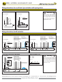
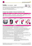
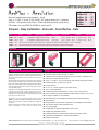
Wiring alternatives for modulating actuators with or without spring return
ExMax-...-Y.., RedMax-...-Y..
Modulating with/without spring rturn
Self adjustment:
To adjust the signal input/output to the Angle
of rotation of the damper/valve the button T
must be pushed for minimum 3 sec.
+
~
YmA YVDC
T
24...230 VAC/DC
~
SB 4.0
VDC/mA
Self adjustment:
To adjust the signal input/output to the Angle
of rotation of the damper/valve the button T
must be pushed for minimum 3 sec.
24...230 VAC/DC
~
UmA UVDC
PE
SB 4.1
+
~
YmA YVDC
T
Modulating or 3-pos with/without spring return
VDC/mA
UmA UVDC
PE
a
b
I
I
A
B
1
2
3
4
1
2
3
4
5
6
heater
A
B
1
PA
2
3
4
1
2
3
4
5
6
heater
Reverse function: I
bridge 3--4 reverse input and output
signals.
PA
Reverse function: I
bridge 3--4 reverse input and output
signals.
Function of switch a and b:
- a closed, On (Off) - in acc. to left/right mounting ot the actuator
- b closed, Off (On) - in acc. to left/right mounting ot the actuator
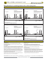
3-pos with/without spring return, plus feedback
Self adjustment:
To adjust the signal input/output to the Angle
of rotation of the damper/valve the button T
must be pushed for minimum 3 sec.
+
~
YmA YVDC
T
24...230 VAC/DC
~
SB 4.2
24...230 VAC/DC
~
VDC/mA
PE
SB 4.3
Self adjustment:
To adjust the signal input/output to the Angle
of rotation of the damper/valve the button T
must be pushed for minimum 3 sec.
+
~
T
Modulating with/without spring return, no feedback
VDC/mA
UmA UVDC
PE
a
I
A
B
1
heater
2
3
4
1
2
3
4
5
6
b
I
A
B
1
PA
2
3
4
1
2
heater
3
4
5
6
PA
Reverse function: I
bridge 3--4 reverse input and output
signals.
Reverse function: I
bridge 3--4 reverse input and output
signals.
Function of switch a and b:
- a closed, On (Off) - in acc. to left/right mounting ot the actuator
- b closed, Off (On) - in acc. to left/right mounting ot the actuator
Over temperature, 3-pos-operation, heating by low ambient temperatures
I. Temperature rise
While operating the ExMax actuator following parameters have to be aligned:
At overload resp. temperature rise the actuator will remain functionless until cooling.
During cooing the LED is red.
II. 3-pos operation
ExMax (RedMax) actuators are in the best way suitable for the 3-pos operation.To protect
such elements as gears and mounting elements against harmful influences like minimum
pulse time, ExMax (RedMax) actuators are protectet via internal electronics. The internal
electronic permits 20 impulses with < 0.5 > sec. cyclic duration, afterwards at least
1 impulse > 1 sec. must follow. If clocked with more than 20 impulses each < 1 sec. the
actuator will adjust into a suspend mode.There after a reset is mandadory and will be
achieved by briefly switching of the supply voltage for about 2 sec..The controll unit has
to be parameterized in order to be set within the above mentioned duration limits.
III. Use at low ambient temparature below - 20°C
All ExMax (Redmax) actuators are equipped with a regulated integrated heating device
designed for employments down to -40°C ambient temperature.
The heater will be supplied automatically by connecting the constant voltage supply on
the clamps 1 and 2.
Following parameters are to be considered by ambient temperaure < 10°C:
1. After mounting the actuator must bei immediately electrically connected.
2. The actuator will only be activated after the operating temperature has reached at least
-20°C .
3. The adjustment options are only ensured after this heating up period.
IV. Mechanical protection
1. The actuator must be operated with an outside load of at least 10 Nm.
2. After installing the actuator to the damper/armature an automatic alignment has to be
accomplished, in order to obtain a "gentle blockade/stop". This function protects the
damper/armature by reducing the end positions/blockade speed in order to avoid
mechanical overload. The actuator alignes specifically once with 90 Sec/90° onto each
position, recognizes the blockade position in order to reduce the motor performance
during operation briefly before reaching the end /blockade position.
Schischek GmbH Germany D-90579 Langenzenn, Mühlsteig 45, Gewerbegebiet V, Tel. ++49 (0)9101-90810, Fax ++49 (0)9101-908177, Email [email protected]
www.schischek.com