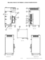
1
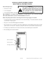
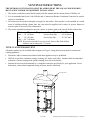
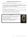
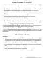
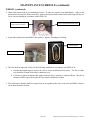
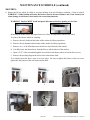
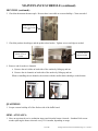
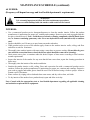
Gas-Fired Wood-Burning Stationary Rack BBQ Smoker OWNER’S MANUAL Southern Pride smokers have been tested and approved by Intertek Testing Services, and are ETL listed to ANSI Z83.11b - 2009, CSA 1.8b - 2009, and to NSF/ANSI Standard 4. ETL File Number 4007026 401 South Mill Street , Alamo, Tennessee 38001 1 of 38 731-696-3175 http://www.southern-pride.com Copyright 2015 by Southern Pride Distributing, LLC Volume 2 Southern Pride smokers are gas-fired, wood-burning, ETL listed, commercial cooking appliances whose installation, operation, and maintenance should comply with the instructions in this manual, NFPA® 96 and other codes and standards as called out in this manual. For more information on NFPA® 96, or to obtain a copy of the latest publication, please contact: NFPA® 1 Batterymarch Park PO Box 9101 Quincy, MA 02169-7471 www.nfpa.org 2 of 38 Copyright 2015 by Southern Pride Distributing, LLC Volume 2 CONGRATULATIONS! In selecting Southern Pride, you have chosen the finest, most advanced and most fully automatic wood burning barbecue smoker available. With us, “ It’s Simply, a Matter of Pride”. Please read this Manual carefully prior to installation, operation and maintenance of your Southern Pride smoker. Proper installation, operation, and maintenance are essential for your satisfaction and safe operation. KEEP THIS MANUAL FOR REFERENCE NOTE: An Electrical Diagram for this appliance can be found on the inside of the service access panel. This smoker may be operated outdoors. 3 of 38 Copyright 2015 by Southern Pride Distributing, LLC Volume 2 TABLE OF CONTENTS Safety Information and Precautions ...................................................................5 Diagram of Controls & Components .............................................................. 6-7 INSTALLATION Receiving the Smoker ...........................................................................................8 Delivery Location..................................................................................................8 Unloading the Smoker..........................................................................................9 Unpacking the Smoker .........................................................................................9 Site Instructions ...................................................................................................9 Electrical Instructions ........................................................................................10 Gas Piping Instructions................................................................................ 11-13 Gas Connection Instructions .............................................................................14 Installation Instructions for Restraining Device .............................................15 Burner Specification...........................................................................................16 Venting Instructions ...........................................................................................17 OPERATION Product Loading Instructions ...........................................................................18 Firebox Loading Instructions ............................................................................19 Control Operating Instructions................................................................... 20-22 Product Unloading Instructions ........................................................................23 Ash Removal Instructions..................................................................................23 Grease Removal Instructions ............................................................................24 Wood Storage Instructions ................................................................................24 Mobile Smoker Operation .................................................................................25 Mobile Smoker Electrical Information ............................................................25 Mobile Smoker Warnings ............................................................................ 25-27 MAINTENANCE Daily .....................................................................................................................28 Weekly ........................................................................................................... 28-29 Monthly ......................................................................................................... 30-31 Quarterly/Semi-Annually ..................................................................................31 As Needed ...................................................................................................... 32-33 Wiring Diagram ..................................................................................................34 Replacement Parts List ......................................................................................35 Before You Call For Service ..............................................................................36 Troubleshooting the Gas Burner ......................................................................37 Limited Warranty ..............................................................................................38 4 of 38 Copyright 2015 by Southern Pride Distributing, LLC Volume 2 SAFETY INFORMATION AND PRECAUTIONS This Manual should be considered a permanent part of this smoker. THE SMOKER MUST BE INSTALLED BY A QUALIFIED SERVICE TECHNICIAN. All troubleshooting guides, component views and parts lists included in this manual are for general reference only and are intended for use by qualified technical personnel. DANGER: Improper installation, alteration, adjustment, service, or maintenance could result in severe injury, death, or cause property damage. Read the installation, operating, and maintenance instructions thoroughly before installing or servicing this equipment. DANGER: Do not store or use gasoline or other flammable vapors or liquids in the vicinity of this or any other appliances. CAUTION: Metal parts and surfaces of this smoker become extremely hot when in operation. To avoid burns, always use hand protection when operating the smoker. WARNING: ELECTRIC SHOCK HAZARD Follow these rules to avoid electric shock. Use only a properly grounded circuit. Do not spray water directly on electrical components. Turn off power before servicing. WARNING: FOR YOUR SAFETY IF YOU SMELL GAS…... 1. Open windows 2. Do not touch electrical switches 3. Extinguish any open flames 4. Immediately call your gas supplier WARNING: CARBON MONOXIDE POISONING HAZARD Carbon monoxide is a colorless, odorless gas that can kill. Follow these rules to control carbon monoxide. Do not use the smoker if in an unvented, enclosed area. Carbon monoxide may accumulate. Allow only qualified burner service persons to adjust the burner. Special instruments and training are required. Read the owner’s manual before using. 1. IT IS EXTREMELY IMPORTANT TO FOLLOW THE PRESCRIBED CLEANING INSTRUCTIONS. GREASE OR SOLIDS BUILDUP INSIDE THE SMOKER COULD RESULT IN A FIRE HAZARD. 2. This smoker is intended for use in commercial facilities where all operators are familiar with the purpose, limitations, and associated hazards of this equipment. The operating instructions and warnings must be read and understood by all operators and users. 3. This manual and all supplied instructions, diagrams, schematics, parts lists, notices and labels must remain with the smoker even if the smoker is sold or moved to another location. 4. The area around the smoker MUST be kept clear and free of combustible materials, gasoline and other flammable vapors and liquids. 5. The flow of combustion and ventilating air MUST NOT be obstructed from reaching the smoker. 6. The frame of the smoker MUST be electrically grounded at all times. See “Electrical instructions”. 7. Caution should be used when opening and closing the firebox door. The door is HOT during operation. 8. DO NOT remove service compartment access panels when smoker is in operation or leave off during operation. 9. Gas burners require the services of a qualified service technician for proper setting and adjustment. If the burner does not appear to be operating properly, DO NOT ATTEMPT TO ADJUST THE BURNER YOURSELF. 10. DO NOT allow unqualified personnel to perform service work or adjustments on this smoker. Doing so, will VOID WARRANTY and could result in a hazardous condition. 11. Ensure new employees, who might operate the smoker, are properly instructed and supervised on the operation and safety information prior to operating the smoker. 12. Ashes removed from the firebox should be stored in a non-combustible container with a sealed lid only. Store ashes in a well ventilated area. FUMES COULD BE HAZARDOUS. 5 of 38 Copyright 2015 by Southern Pride Distributing, LLC Volume 2 DIAGRAM OF CONTROLS AND COMPONENTS 7 1 6 10 9 8 4 12 13 11 5 2 3 Front View Rear View Top View Left Side View Right Side View 6 of 38 Copyright 2015 by Southern Pride Distributing, LLC Volume 2 DIAGRAM OF CONTROL AND COMPONENTS 1. DIGITAL COOK & HOLD CONTROL - Provides precise temperature control of the smoker along with control of the other functions of the smoker. 2. FLUE - Designed for use with Type-1 Canopy hood. 3. GREASE DRAIN PAN – Opening in bottom of smoker allows grease to drain from Smoker into pan during the cook cycle. Pan must be emptied after each cook cycle. 4. FIREBOX DOOR - Provides access to the firebox chamber for loading wood and ash removal. Keep closed while cooking. 5. 6” LOCKING CASTER WHEELS - Heavy duty locking casters provide a solid base and offers convenient mobility. 6. DATA PLATE - Label containing smoker’s serial number, model number, manufactured date, etc. 7. CONTROL / FAN MOTOR COMPARTMENT – Location of the convection fan motor, control module and relay board. 8. SERVICE COMPARTMENT COVER - Access to service bay where burner is located. 9. PRODUCT LOADING DOOR – Provides access to load/unload product and for cleaning the interior of the smoker. 10. PRODUCT LOADING DOOR LATCHES - Latches apply positive pressure and seals doors. 11. GAS SUPPLY CONNECTION - Drip leg connection point for incoming gas supply to smoker. 12. POWER CORD CONNECTION - Access point for supply power cord to smoker. 13. TETHER / WALL ANCHOR BOLT MOUNTING LOCATION - Threaded hole for installation of eyelet bolt used to attach restraining device for smokers mounted on caster wheels to guard against transmission of strain to the gas and electrical connections. Required by ANSI Z83.11b - 2009. 7 of 38 Copyright 2015 by Southern Pride Distributing, LLC Volume 2 INSTALLATION RECEIVING THE SMOKER Your smoker can be shipped via a contract hauler on a flatbed trailer, or Common Carrier. Once the smoker arrives you will need a forklift to remove the crated smoker from the truck (Common Carrier deliveries). Model SRG-400 Approx. Wt. Approx. Wt. Uncrated Crated 780 lb. 1,005 lb. NOTE: The above weights are for the base model only. DELIVERY LOCATION Commercial smokers are large and heavy. Before scheduling the delivery of your smoker have a plan and location in place to accept the delivery of the smoker and maneuver the smoker into the desired installation location. The trucker will require a flat, level surface that is safe from traffic to unload the smoker. A forklift will be required to unload the smoker. The trucker is only responsible for delivery of the smoker. It is your responsibility to unpack the smoker, move it to its installation location, and install the smoker. WARNING: If the forklift forks are not long enough to support the entire smoker/crate do not attempt to move the smoker; obtain another forklift or use fork extensions. WARNING: Only proper heavy lifting machinery and heavy lifting equipment should be used for unloading, moving and installing the smoker. This duty should only be performed by professionals trained in this kind of work. Improper handling of the equipment could result in damaging the smoker or personal injury and even death. 8 of 38 Copyright 2015 by Southern Pride Distributing, LLC Volume 2 UNLOADING THE SMOKER Smokers Shipped via Common Carrier Remove the crated smoker from the truck using the appropriate forklift. Note any damage to the crate, smoker or accessories. Do not sign the delivery bill until the smoker has been inspected and any damage noted on the delivery bill. The smoker is shipped strapped to a wooden pallet with an industrial cardboard carton. Once the smoker is in a level and safe place remove the cardboard carton and open the product loading door. Plastic zip ties secure a cardboard box to one of the product racks of the smoker. Remove the cardboard box from the product rack. Cardboard covers protect each product rack during shipment. Remove the cardboard protectors from each product rack. Located on top of the wooden pallet are two (2) wooden ramps. Fasten the ramps to the edge of the wooden pallet using the metal clasps located on the end of the pallet and ramps. The smoker is secured to the wooden pallet with metal banding straps. A 2 x 4 prevents the smoker from moving. After removing the banding straps securing the smoker to the wooden pallet and the 2 x 4 (with a Phillips screwdriver), release the brakes on each of the smokers casters. Then the smoker can be slowly and carefully rolled down the ramps secured to the pallet. Smokers Shipped via Contract Hauler The driver will unload the smoker from the trailer. Once the smoker is in a level and safe place remove the white protective wrap from the outside of the smoker and open the product loading door. Plastic zip ties secure a cardboard box to one of the product racks of the smoker. Remove the cardboard box from the product rack. Cardboard covers protect each product rack during shipment. Remove the cardboard protectors from each product rack. UNPACKING THE SMOKER The 6” drain pan inside the smoker contains the following items: Sample seasoning and sauces. Bulk sizes are available. Please contact your authorized Southern Pride distributor for additional information. Restraining device. SITE INSTRUCTIONS The Southern Pride smoker must be installed in a location that will permit the smoker to function for its intended purpose and to allow adequate clearance for ventilation, proper cleaning, and maintenance access. Minimum Clearance Requirement from Combustible Material Back…...18” (457mm) Front…………….……...48” (1219mm) Top…….18” (457mm) Right & Left Side...……...2” (51mm) NOTE: If provision is made for service access, back clearance can be reduced to 2” (51mm). WARNING: Failure to maintain proper safety, storage, handling, and ash removal for solid fuel appliances on or around combustible materials may result in fire, property damage and/or death. Our product listing allows for the smoker to be installed on a combustible surface however, Southern Pride recommends the use of a noncombustible material for the floor surface area under the fire box, which should extend at least 6” beyond each side of the fire box, and outward from the smoker beyond the area needed for placement of the ash container. 9 of 38 Copyright 2015 by Southern Pride Distributing, LLC Volume 2 INSTALLATION INSTRUCTIONS ELECTRICAL INSTRUCTIONS Electrical Requirements: 120 volts AC, 60 Hz 2 wire, single phase 15 amp required, NEMA 5-15P plug WARNING: This appliance, when installed, must be electrically grounded in accordance with local codes, or in the absence of local codes, with the National Electrical Code, ANSI/NFPA 70, or the Canadian Electrical Code, CSA C22.2, as applicable. THE WARRANTY IS VOID IF THE SMOKER IS CONNECTED TO ANY VOLTAGE OTHER THAN SPECIFIED ABOVE AND ON THE SMOKER DATA PLATE. Remove all packing material before connecting the electrical and gas supply to the smoker. An electrician must provide the conduit and wire for electrical hookup. The smoker should be connected to a dedicated 15 amp receptacle. The power is to be left OFF throughout the installation. The electrical service is connected via the factory supplied power cord normally located to the rear of the smoker on the service bay side. Alternatively, the power cord can be removed and the smoker hard wired. 5. If venting or gas connections are to be done at a later time, be sure that the power remains OFF. 6. The restraining device must be installed. Electrical Connection Tether Connection Gas Supply Connection 10 of 38 Copyright 2015 by Southern Pride Distributing, LLC Volume 2 GAS PIPING INSTRUCTIONS IMPORTANT NOTES TO THE INSTALLER Read all instructions contained in this Owner’s Manual before making gas connections. Ensure all packing material is removed from the smoker compartments before connecting the gas supply to the smoker. Be sure your smoker is installed and grounded properly by a qualified service technician. Observe all governing codes and ordinances. WARNING: IMPROPER GAS HOOKUP WILL VOID WARRANTY AND COULD RESULT IN A HAZARDOUS CONDITION. 1. All local and national codes and ordinances must be observed. Installation must conform with local codes or in the absence of codes, the National Fuel Gas Code ANSI Z223.1 / NFPA-54, latest edition available from The American Gas Association, Inc., 1515 Wilson Boulevard, Arlington, VA 22209. 2. The gas supply (service) line must be the same size or greater than the inlet line of the appliance. This smoker uses a 1/2” (1.3 cm) ID NPT (Sch40) inlet. Sealant on all pipe joints must be resistive to LP gas. 3. Supply line and manifold pressure should be checked with a manometer. Refer to page 16 for minimum and maximum pressures. Incoming line pressure upstream from the regulator must be 1” W.C.P. higher than the manifold pressure in order to check the regulator. The regulator used on this smoker can withstand a maximum input pressure of 1/2” PSI (14.0” W.C.P.). Over pressuring the valve may cause damage to the valve. If the line pressure is in excess of that amount, a step down regulator will be required. 4. It is recommended new pipe be used and located so that a minimum amount of work will be required in future servicing. The piping should be so installed as to be durable, substantial, and gas tight. It should be free from cutting burrs and defects in structure and threading. Cast iron fittings or aluminum tubing should not be used for the main gas circuit. Joint compounds (pipe dope) should be used sparingly on male threads only and be approved for all gases. NOTE: The building structure should not be weakened by installation of the gas piping. The piping should not be supported by other piping, but should be firmly supported by pipe hooks, straps, bands, or hangers. Butt or lap welded pipe should not be bent. 5. TEST PIPING FOR LEAKS. Before turning gas under pressure into piping, all openings from which gas can escape must be closed. Immediately after turning on gas, the system should be checked for leaks. This can be done by watching the 1/2 cubic foot test dial for 5 minutes to show any movement, or by soaping each pipe connection and watching for bubbles. If a leak is found, make the necessary repairs and repeat the above test. NOTE: Defective pipes or fittings should be replaced and not repaired. Never use a flame or fire of any form to locate gas leaks, use a soap solution. 6. After the piping and meter have been checked completely, PURGE THE SYSTEM OF AIR. DO NOT bleed the air inside the smoker. Be sure to relight all the gas pilots on other appliances. NOTE: The burner and its individual shutoff valve must be disconnected from the gas supply piping system during any pressure testing in excess of 1/2 psig. 11 of 38 Copyright 2015 by Southern Pride Distributing, LLC Volume 2 GAS PIPING INSTRUCTIONS Pipe Sizing Chart for Natural Gas (0-0.5 psi) with Straight Schedule 40 Metal Pipe The following chart is based on 0-0.5 psi inlet pressure, specific gravity of 0.6, and a pressure loss of 0.5” w.c. Maximum Capacity of Pipe Size in Btu per Hour Pipe Size 1/2” 3/4” Pipe Length (ft) 1” 1 1/4” 1 1/2” Maximum Capacity in Btu/hr 10 175,000 360,000 680,000 1,400,000 2,100,000 20 120,000 250,000 465,000 950,000 1,460,000 30 97,000 200,000 375,000 770,000 1,180,000 40 82,000 170,000 320,000 660,000 990,000 50 73,000 151,000 285,000 580,000 900,000 60 66,000 138,000 260,000 530,000 810,000 70 61,000 125,000 240,000 490,000 750,000 80 57,000 118,000 220,000 460,000 690,000 90 53,000 110,000 205,000 430,000 650,000 100 50,000 103,000 195,000 400,000 620,000 150 40,000 84,000 160,000 325,000 500,000 200 35,000 72,000 135,000 280,000 430,000 Pipe Sizing Chart for Liquid Propane (11” w.c.) with Copper Tubing The following chart is based on 11” w.c. inlet pressure and a pressure drop of 0.5” w.c. NOTE: Copper tubing shall comply with standard type K or L of ASTM B 88 or STM B 280. Maximum Capacity of Tube Size in Btu per Hour Pipe Size 1/2” Pipe Length (ft) 5/8” 3/4” 7/8” Maximum Capacity in Btu/hr 10 110,000 206,000 348,000 536,000 20 76,000 141,000 239,000 368,000 30 61,000 114,000 192,000 296,000 40 52,000 97,000 164,000 253,000 50 46,000 86,000 146,000 224,000 60 42,000 78,000 132,000 203,000 70 38,000 71,000 120,000 185,000 80 36,000 67,000 113,000 174,000 90 33,000 62,000 105,000 161,000 100 32,000 59,000 100,000 154,000 12 of 38 Copyright 2015 by Southern Pride Distributing, LLC Volume 2 GAS PIPING INSTRUCTIONS (continued) Pipe Sizing Chart for Liquid Propane (11” w.c.) with Straight Schedule 40 Metal Pipe The following chart is based on 11” w.c. inlet pressure and a pressure drop of 0.5” w.c. Maximum Capacity of Pipe Size in Btu per Hour Pipe Size 1/2” 3/4” 1” 1 1/14” 1 1/2” 2” 3” Actual ID 0.622 0.824 1.049 1.38 1.61 2.067 3.068 Pipe Length (ft) Maximum Capacity in Btu/hr 10 291,000 608,000 1,145,000 2,352,000 3,523,000 6,786,000 19,119,000 20 200,000 418,000 787,000 1,616,000 2,422,000 4,664,000 13,141,000 30 160,000 336,000 632,000 1,298,000 1,945,000 3,745,000 10,552,000 40 137,000 287,000 541,000 1,111,000 1,664,000 3,205,000 9,031,000 50 122,000 255,000 480,000 984,000 1,475,000 2,841,000 8,004,000 60 110,000 231,000 434,000 892,000 1,337,000 2,574,000 7,253,000 80 94,000 197,000 372,000 763,000 1,144,000 2,203,000 6,207,000 100 84,000 175,000 330,000 677,000 1,014,000 1,952,000 5,501,000 125 74,000 155,000 292,000 600,000 899,000 1,730,000 4,876,000 150 67,000 140,000 265,000 543,000 814,000 1,568,000 4,418,000 200 58,000 120,000 227,000 465,000 697,000 1,342,000 3,781,000 250 51,000 107,000 201,000 412,000 618,000 1,189,000 3,351,000 300 46,000 97,000 182,000 373,000 560,000 1,078,000 3,036,000 350 42,000 89,000 167,000 344,000 515,000 991,000 2,793,000 400 40,000 83,000 136,000 320,000 479,000 922,000 2,599,000 13 of 38 Copyright 2015 by Southern Pride Distributing, LLC Volume 2 GAS CONNECTION INSTRUCTIONS For smokers equipped with casters, the installation shall be made with a connector that complies with the Standard for Connectors for Movable Gas Appliances, ANSI Z21.69 CSA 6.16, and a quick-disconnect device that complies with the Standard for Quick-Disconnect Devices for Use With Gas Fuel, ANSI Z21.41 CSA 6.9. Adequate means must be provided to limit the movement of the appliance without depending on the connector and the quick-disconnect device or its associated piping to limit the appliance movement. The restraining device may be attached using the mounting hole provided on the rear of the smoker. Refer to page 6 to locate the mounting hole and page 15 for the installation instructions. WARNING: Operator should be aware that a restraint device is in place on smokers equipped with casters. If disconnection of the restraint is necessary, it must be reconnected after the appliance has been returned to its originally installed position. IMPORTANT ITEMS TO CHECK BEFORE FIRING THE BURNER 1. Gas line MUST be installed by a qualified technician and in accordance with this Manual. 2. Gas line MUST include an easily accessible manual shutoff valve, drip leg, and pressure gauge port. 3. Gas pipe size MUST be in accordance with the Pipe Capacity Chart in this Manual (pages 12 and 13). 4. Gas line MUST be tested for leaks under pressure. 5. Gas line MUST be purged to remove any air in the system. 6. Gas line pressure MUST be checked and MUST NOT exceed the maximum pressure specified in the Burner Specifications on page 16. 7. Burner orifice MUST correlate with the type of gas being supplied, as specified in the Burner Specifications on page 16. WARNING: Improper gas hookup will void the warranty and could result in a hazardous condition. 14 of 38 Copyright 2015 by Southern Pride Distributing, LLC Volume 2 INSTALLATION INSTRUCTIONS FOR RESTRAINING DEVICE 1. Restraining device should be installed parallel (in line) with the power supply cord. 2. Restraining device parts list: See Figure A for a photo of the materials contained in the restraining kit. 3. Attach staple bracket: Fasten the staple bracket (Figure B) to a stud located in the wall that the power receptacle is located on. Use the (4) #10 x 1” screws and plastic anchors if needed. 4. Install eyebolt: Thread jam nut onto eyebolt. Screw eyebolt into threaded hole below the power cord connection point on back of smoker. Tighten eyebolt and then tighten jam nut to keep eyebolt tight (Figure C). 5. Connect restraining cable: Attach one end of cable using the spring loaded hook to the eyebolt. Attach other end of cable to the staple bracket using the other spring loaded hook. 6. Note: To provide strain relief the restraining cable must be shorter than the power supply cord and gas line. The restraining device should always be connected when the smoker is in use. 2 1 4 3 5 7 Figure A 1. Staple bracket 2. Eyebolt with jam nut 3. Restraining cable 4. Spring loaded hook 5. #10 x 1” screws 6. Plastic anchors 7. Instruction sheet 6 Figure B Figure C 15 of 38 Copyright 2015 by Southern Pride Distributing, LLC Volume 2 BURNER SPECIFICATIONS Burner Models: Wayne P265-EP Fuels: Natural or L.P. Gases Electrical: 120 V.A.C., 60 Hz, 1 ph NOTE: Orifice and valve setting must correlate with type of gas being supplied. Main Orifice Size Chart 65,000 Btu/hr Natural Gas #26 (.147") Firing Capacity Firing Rate Btu 65,000 SRG-400 65,000 Btu/hr X Gas Supply Line Pressure Pilot Orifice Size Chart Natural BCR-24 LP BCR-18 LP Gas #43 (.089") Manifold Pressure Minimum Maximum Minimum Maximum Natural 4.5” w.c. 10.0” w.c. 3.0” w.c. 3.5” w.c. LP 11.0” w.c. 13.0” w.c. 9.5” w.c. 10.0” w.c. Gas valve: Control knob must be ON. Gas valveOn position Supply gas pressure test port Wiring Diagram for Gas Burner 16 of 38 Copyright 2015 by Southern Pride Distributing, LLC Volume 2 VENTING INSTRUCTIONS THE METHOD OF VENTILATION MUST BE APPROVED BY THE LOCAL CODE ENFORCEMENT AGENCY PRIOR TO EQUIPMENT INSTALLATION. 1. The smoker ventilation system should comply with this manual and the current edition of NFPA® 96. 2. It is recommended that Local Code Officials and a Commercial Kitchen Ventilation Contractor be consulted prior to installation. 3. Provisions must be made for adequate air supply for the smoker. If the smoker is to be installed in a sealed room or building utilizing exhaust fans, the room must be supplied with a return air system. Return air must be equal or in excess of the exhausted air. 4. The smoker should be positioned to provide a direct, or shortest, path to the outside for the exhaust duct. Minimum Clearance Requirement from Combustible Material Back…...18” (457mm) Firebox Door Side……...24” (610mm) Top…….18” (457mm) Service Bay Side……….18” (457mm) Front…...48” (1219mm) NOTE: If provision is made for service access, Service Bay Side & Back clearance can be reduced to 2” (51mm). TYPE-1 CANOPY HOOD VENT All smoker models may be installed under an approved Type-1 canopy hood system rated for commercial cooking appliances. Placement under a common hood shared with other appliances may be prohibited. NFPA® 96 specifies a minimum canopy overhang of 6 inches on all sides. Southern Pride recommends a minimum 18 inch overhang on the product loading door side of the smoker. Exhaust fan size must be determined by a ventilation contractor specifically for your application. Hood dimensions, exhaust duct length and routing all factor into the calculation. Canopy Hood 17 of 38 Copyright 2015 by Southern Pride Distributing, LLC Volume 2 OPERATION The smoker should be operated in the following order (with all operations according to the subsequent instructions): 1. Load the product into the smoker and close the product loading doors. 2. Place the desired wood into the firebox and close the firebox door. 3. Ensure that the drain pan is empty and installed in the pan rails located under the smoker drain hole. 4. Set the control and start the cook cycle. 5. Once the cook cycle is complete, turn the control off. 6. Remove the product from the smoker. 7. Remove the ashes from the firebox. 8. Empty the grease from the grease pan. PRODUCT LOADING INSTRUCTIONS The smoker is equipped with seven (7), 18” x 26” product racks in its standard configuration for the loading of product. The modular designed rack slide system has 1.5” spacing that allows the smoker to hold up to 27 product racks at one time. 1. Remove the wire product rack from the smoker. 2. Place the product directly on the product rack, leaving an air gap between each piece of product. 3. With the product placed on the rood rack, carefully slide the loaded product rack into the smoker starting from the bottom rack slide position. 4. Repeat steps 2 and 3 until all product is loaded into the smoker. Product height will determine how many rack slide spaces you need to advance to maintain an air gap between each loaded product rack. 18 of 38 Copyright 2015 by Southern Pride Distributing, LLC Volume 2 FIREBOX LOADING INSTRUCTIONS 1. The solid fuel should be handled in accordance with NFPA® 96. 2. Ensure the control is OFF, or in the Idle or Pause position, before opening the firebox door. 3. Use 1-3 logs, 3-5 inches in diameter, 10-12 inches long. Use green or slightly seasoned hardwoods, fruitwoods, or charcoal (not to exceed six pounds). THE WOOD OR CHARCOAL IS ONLY USED TO FLAVOR THE PRODUCT, NOT TO HEAT THE SMOKER. 4. Be sure to keep the wood 4” from the burner or ashes can accumulate on the burner and cause it to not work properly. 5. Place the logs on top and inline with each other to minimize air flow around each log. This will help promote a smoldering, slow burn, which maximizes smoke. 6. The wood does not have to be lit manually; the smoker is equipped with a gas burner that will light the wood. Combustible or flammable liquids shall not be used to assist ignition. 7. Tightly close the firebox door to prevent air from being pulled into the firebox. 8. If the cook menu was paused, a press of the start button is required to resume the menu.. CAUTION: Remove coals and ashes from previous cook cycle before loading new wood into the firebox. Refer to Ash Removal Instructions on page 23. Do not use dry wood or kindling. Do not overload firebox. Too much wood or charcoal can cause overheating of the smoker. Keep wood at least 4 inches from the burner. Do not allow ashes in or near the burner opening. 19 of 38 Copyright 2015 by Southern Pride Distributing, LLC Volume 2 CONTROL OPERATING INSTRUCTIONS DIGITAL ROAST & HOLD CONTROL - Manual Menu 1. The product loading doors must be closed. 2. The control should be in the “IDLE” mode. (The burner, and convection fan will be off). If the control is “OFF” a press of any button will bring the control back to “IDLE.” 3. A menu consists of a cook temperature, cook time, and, when the cook time has elapsed, a choice to end the menu (HOLD OFF) or go into hold mode (HOLD TEMP SETPOINT). 4. Press the manual menu button (tEnP 1 will appear in the LED display), then press the up/down buttons to obtain the desired cook temperature. 5. Press the manual menu button (tinE1 will appear in the LED display), then press the up/down buttons to obtain the desired cook time. 6. Press the manual menu button (HtEnp will appear in the LED display), press the up/down buttons to obtain the desired hold temp, if a hold temp is not desired press the down button until “OFF” is displayed in the LED. 7. Programming the menu is complete. To start the menu, press the start/stop button one time. The control will begin the menu. 8. To cancel or stop the menu, press and hold the start/stop button until “IDLE” is displayed in the LED. 9. When the cook cycle is complete there are two possible actions that can be taken. One is if a hold temperature was programmed into the menu, the control will momentarily sound an audible alarm then, “HOLD” and the length of time the control has been in the hold mode will alternately flash in the LED display. The control will maintain the hold temperature until the start/stop button is depressed to “END” the menu, and bring the control to the “IDLE” mode. 10. If the hold temperature was programmed to “OFF” and the cook time has elapsed, “END” will be displayed on the LED display, and an audible alarm will sound continuously until the start/stop button is depressed, to “END” the menu, and bring the control to the “IDLE” mode. 11. After the control has been in the “IDLE” mode for five minutes it will go to “OFF”, a press of any button will bring the control back to “IDLE”. 12. After each cook cycle the ashes should be removed from the firebox, the grease emptied from the drain pan, and the cool down cycle should be ran. To start a cool down cycle; press the cook temp button and then press the down button until “OFF” is displayed in the LED display. This turns off the gas burner. Press the start/stop button to start the cool down cycle. Run the cool down cycle until the smoker temperature falls below 90°. 20 of 38 Copyright 2015 by Southern Pride Distributing, LLC Volume 2 CONTROL OPERATING INSTRUCTIONS (continued) DIGITAL ROAST & HOLD CONTROL - Automatic Menu Programming 1. The product loading doors must be closed. 2. The control should be in the “IDLE” mode. (The burner, and convection fan will be off). If the control is “OFF” a press of any button will bring the control back to “IDLE.” 3. A menu consists of a cook temperature, cook time, and, when the cook time has elapsed, a choice to end the menu (HOLD OFF) or go into hold mode (HOLD TEMP SETPOINT). 4. Press and hold the up and down buttons for 10 seconds to access the menu program state (M 1 will appear in the LED display). 5. Press the manual menu button to access the menu parameters for menu 1 (St PT 1 will appear in the LED display), this is the set point temperature for the menu. 6. Press the manual menu button again to change the cook temperature. Use the up/down buttons to obtain the desired cook temperature. Press the enter button to save the change. 7. Press the down button to advance to cook time (tine 1 will appear in the LED display). To change the cook time, press the manual menu button. Use the up/down buttons to obtain the desired cook time. Press the enter button to save the change. 8. Press the down button to advance to hold temperature (H St Pt 1 will appear in the LED display). To change the hold temperature, press the manual menu button. Use the up/down buttons to obtain the desired hold temperature, if a hold temperature is not desired press the down button until “OFF” is displayed in the LED. Press the enter button to save the change. 9. Programming the menu is complete. Press the enter button to return to the menu list. Use the up/down buttons to select the next menu to program. Repeat the above steps to program the next menu. Once programming is complete, press the enter button twice to return to “IDLE”. 21 of 38 Copyright 2015 by Southern Pride Distributing, LLC Volume 2 CONTROL OPERATING INSTRUCTIONS (continued) DIGITAL ROAST & HOLD CONTROL - Automatic Menu Operation 1. The product loading doors must be closed. 2. Press the auto menu button. The number of the first automatic menu will be displayed in the LED display. 3. Use the up/down buttons to scroll through the list of automatic menus. When the desired menu number is displayed in the LED, press the start/stop button to start the menu. 4. To cancel or stop the menu, press and hold the start/stop button until “IDLE” is displayed in the LED. 5. When the cook cycle is complete there are two possible actions that can be taken. One is if a hold temperature was programmed into the menu, the control will momentarily sound an audible alarm then, “HOLD” and the length of time the control has been in the hold mode will alternately flash in the LED display. The control will maintain the hold temperature until the start/stop button is depressed to “END” the menu, and bring the control to the “IDLE” mode. 6. If the hold temperature was programmed to “OFF” and the cook time has elapsed, “END” will be displayed on the LED display, and an audible alarm will sound continuously until the start/stop button is depressed, to “END” the menu, and bring the control to the “IDLE” mode. 7. After the control has been in the “IDLE” mode for five minutes it will go to “OFF”, a press of any button will bring the control back to “IDLE”. 8. After each cook cycle the ashes should be removed from the firebox, the grease emptied from the drain pan, and the cool down cycle should be ran. To start a cool down cycle; press the cook temp button and then press the down button until “OFF” is displayed in the LED display. This turns off the gas burner. Press the start/stop button to start the cool down cycle. Run the cool down cycle until the smoker temperature falls below 90°. 22 of 38 Copyright 2015 by Southern Pride Distributing, LLC Volume 2 PRODUCT UNLOADING INSTRUCTIONS 1. Before unloading the product, the control should be in the “OFF” or “IDLE” position. 3. Carefully open the product loading door just enough to release the smoke from the cabinet, then wait approximately 5 seconds before fully opening the product loading door. 4. Product should be removed from top rack to the bottom rack. ASH REMOVAL INSTRUCTIONS 1. The ashes should be handled in accordance with NFPA® 96. 2. After each cook cycle, remove the remaining wood and hot coals from firebox. Use heat resistant gloves while handling ash container and ash removal tools. 3. Place small lots of them in a noncombustible corrosion resistant pan and spray with water. A noncombustible corrosion resistant pan should be kept just outside the firebox door for this purpose. 4. Once wood and ash have been sprayed, place them in a heavy metal container with a tight fitting metal lid (16 gauge minimum, capacity not to exceed 20 gallon). This container shall be assigned for this one purpose, shall be able to be handled easily by any employee assigned the task, and shall pass easily through any passageway to the outside of the building. The container shall always be covered when it is being moved through the premises. When any hole occurs in a container from corrosion or damage, the container shall be repaired or replaced immediately. 5. The ashes should be carried to a separate heavy metal container (or dumpster), outside the premises, that is used exclusively for the purpose of hot ash storage. WARNING Never empty ash/coals from the smoker into a common trash dumpster. Embers from ash/coals could ignite materials resulting in a fire. CAUTION Be sure smoker product loading door(s) and firebox door are secured in the closed position immediately following a cook cycle and during non-use periods. 23 of 38 Copyright 2015 by Southern Pride Distributing, LLC Volume 2 GREASE REMOVAL INSTRUCTIONS WARNING Do not remove the drain pan while the smoker is still in operation or while burning wood and hot coals are still in firebox. 1. Immediately empty the grease pan after each cook cycle. CAUTION: Grease will be hot. 2. Grease should be poured into an approved grease recycling bin. WOOD STORAGE INSTRUCTIONS The solid fuel should be stored in accordance with NFPA® 96. Wood stored in the same room as the smoker or the smoker firebox door shall not exceed a 1-day supply. Wood shall not be stored above any heat-producing appliance or vent or closer than 0.92 m (3ft) to any portion of a solid fuel appliance constructed of metal or to any other cooking appliance that could ignite the wood. Wood shall not be stored in the path of ash removal. Where stored in the same building as the smoker, wood shall be stored only in an area with walls, floor and ceiling of noncombustible construction extending at least 0.92m (3ft) past the outside dimension of the storage pile. Wood shall be separated from all flammable liquids, all ignition sources, all chemicals, and all product supplies and packaging goods. All wood storage areas shall be provided with a sprinkler system meeting the requirements of NFPA® 13. Exceptions: Where acceptable to the authority having jurisdiction, wood storage areas shall be permitted to be protected with a fixed water pipe system with a hose capable of reaching all parts of the area. In lieu of a sprinkler system a listed 2-A rated water spray extinguisher or a 6 L (1.6 gal) wet chemical fire extinguisher listed for Class K fires with a maximum travel distance of 6 m (20 ft.) to the wood piles shall be permitted to be used for a wood pile, provided that the wood pile does not exceed 0.14 cubic meters (5 cubic feet) volume. 24 of 38 Copyright 2015 by Southern Pride Distributing, LLC Volume 2 MOBILE SMOKER OPERATION Check the fuel level of the LP tanks prior to starting a cook cycle. Proper monitoring of the LP tanks will eliminate the chance of running out of gas. The burner in the smoker is equipped with an automatic ignition system. Do not attempt to manually light the burner. Do not transport the smoker while the smoker is in operation or with product on the product racks. Disconnect the electrical power supply before removing the service compartment access panels for servicing. Do not transport the smoker with hot coals or a wood fire in the firebox. Never place anything over the flue of the smoker, it must be unobstructed to work properly. Never attempt to cook with the product door(s), or firebox door, open. Dry wood, too much wood, or too much charcoal may cause the temperature in the smoker to override the thermostat setting. Follow instructions in this manual for the proper amount of wood or charcoal to use. MOBILE SMOKER ELECTRICAL INFORMATION This smoker is equipped with a power cord with a 3 prong grounded plug. DO NOT cut or remove the grounding prong from the smoker power cord or from any extension cord used with the smoker. The smoker should only be plugged into a 120 VAC, 15 amp, grounded receptacle. Use only a 3 prong grounded extension cord rated for outdoor use marked with a “w” (formerly w-A). This designation indicates the cord is rated for outdoor use and includes sunlight resistant jacket and wet location rated conductors. MOBILE SMOKER WARNINGS GENERAL 1. Mobile smokers are intended for outdoor use. NEVER use in a garage, building, shed, breezeway or other enclosed area. The mobile smoker shall not be used under any overhead combustible construction. 2. Store your smoker in a well-ventilated area. If stored indoors, detach and leave LP cylinders outdoors in a well-ventilated area away from heat and away from where children may tamper with them. 3. Keep the electrical supply cord and the fuel supply hose away from any heated surfaces. 4. Do not remove service compartment access panels when smoker is in operation or leave off during operation. 5. After a period of storage or nonuse, check the smoker for gas leaks and burner obstructions before use. 6. Wheel chocks must be used when the smoker is sitting stationary. 7. Level the smoker, both front to back and side to side, before operating the smoker. 25 of 38 Copyright 2015 by Southern Pride Distributing, LLC Volume 2 MOBILE SMOKER WARNINGS (continued) ELECTRICAL 1. To protect against electrical shock: a) do not immerse any part of the power cord, plug or extension cord in water or any other liquid. b) use only a 3 prong extension cord, and only plug into a 15 amp grounded receptacle. 2. Unplug the smoker from the outlet when not in use and before cleaning. 3. Do not let the extension cord hang over the edge of a table or touch hot surfaces. Keep the cord out of walkways to avoid a tripping hazard. 4. Do not use this smoker for purposes other than intended. 5. Do not operate this smoker with a damaged cord, plug, or after the smoker malfunctions or has been damaged in any manner. LP GAS 1. The LP cylinders must be constructed and marked in accordance with the specifications for LP gas cylinders by the U.S. Department of Transportation (DOT), or CAN/CSA B339. 2. The handling, storage and transportation of gas cylinders must be in accordance with storage and handling of Liquid Petroleum Gases, ANSI/NFPA 58 or Natural Gas and Propane Installation Code, CSA B149.1. 3. Cylinders must be secured using the provided cylinder retention system to avoid accidental movement. Exchange only for Type 1, 40lb cylinders with over-fill protection devices. Never use a cylinder with a damaged valve. A dented or rusty LP cylinder may be hazardous and should be avoided. If in doubt, have the cylinder checked by your LP supplier. Always check for leaks after every LP cylinder change. 4. Always shut off the LP gas supply at the cylinder when the smoker is not in use. 5. Cylinders must be stored outdoors in a well-ventilated area out of the reach of children. If your smoker is stored indoors, the LP cylinder must be removed and stored outside. LP gas cylinders are not to be stored in any compartment on the smoker that is not intended for cylinder storage. Such unauthorized storage could lead to an explosion, fire, or personal injury. 6. Cylinders should not be allowed to remain in a high heat area such as a closed car, trunk, or in direct sunlight. 26 of 38 Copyright 2015 by Southern Pride Distributing, LLC Volume 2 MOBILE SMOKER WARNINGS (continued) LP GAS (continued) 7. Before each use, inspect the gas hose. If excessive abrasion, wear or if the hose is cut it must be replaced prior to the smoker being put into operation. 8. LEAK TESTING: Do not use a flame to check for a gas leak. To prevent fire or explosion hazard, DO NOT smoke or allow any potential source of ignition (sparks, electrical arcing, etc.) in the area while performing a leak test. Leak tests should be conducted outdoors only. a. Create a soapy solution of 1 part soap and 1 part water, or use a gas leak detector solution available for purchase from a plumbing supply or hardware store. Confirm that all control knobs are in the off position. b. Open the gas supply valves and apply the soap solution generously by paint brush or squirt bottle on all connections and fittings. If bubbles appear to “grow” on any of the connections, you have a gas leak, immediately turn off the gas supply. 9. Fixing a gas leak: Wash off the soapy solution with cold water and dry. Tighten the loose joint, or replace the faulty part with manufacturer-recommended replacement parts. 10. Do not attempt to repair the LP cylinder valve if it is damaged. The only way to safely resolve a damaged cylinder is to replace it. 11. Repeat the leak test to ensure that no leaks are present. 12. Do not operate the smoker if there is a gas leak present. 13. Leaking gas may cause a fire or explosion which can cause serious bodily injury or death. 14. When not in use, the gas valve on the LP tanks must be turned off and the supply line disconnected from the tanks. The protective dust cap must be installed on the valve outlet. 15. Liquid propane is not natural gas. The conversion to or attempted use of natural gas in a liquid propane smoker is dangerous and will void your warranty. 16. Do not attempt to disconnect any gas fitting while your smoker is in operation. 17. Although your liquid propane cylinder may appear to be empty, gas may still be present. The cylinder should be transported and stored with the valve closed. 27 of 38 Copyright 2015 by Southern Pride Distributing, LLC Volume 2 MAINTENANCE SCHEDULE WARNING It is extremely important to follow the below maintenance procedures. Grease or solids buildup inside the smoker could result in a fire hazard. WARNING: Before any service is performed on the smoker, the gas supply should be turned off and the power disconnected. DAILY: 1. Remove all product racks from smoker and take to sink area for cleaning. Use a commercial foodservice detergent / degreaser. Follow the product manufacturer’s instructions for proper use, cautions and warnings. Protective gear such as goggles and rubber gloves should be used. 2. Sanitize product racks with a commercial product service sanitizer. Follow the product manufacturer’s instructions for proper use, cautions and warnings. Protective gear such as goggles and rubber gloves should be used. 3. Drain grease after each cook cycle. Refer to the Grease Removal Instructions on page 24 of this manual. 4. Remove ashes and coals from firebox after each cook cycle. Refer to the Ash Removal Instructions on page 23 of this manual. WEEKLY: 1. Remove and clean the product door latches. a. After the smoker has been turned off and given time to cool, open the product door(s) leaving the roller in the open position. b. Using a crescent wrench on the edge of the latch cover, apply force to the crescent wrench towards the smoker to pop the latch cover free, and then the latch can be lifted away from the backing plate. c. TO RE-INSTALL: Position the door latch, with the roller in the up position, over the backing plate, fastening the hooks on the latch over the tabs on the backing plate. Using the palm of your hand, push the bottom of the latch into the backing plate until it locks in position. a. b. c. CAUTION: The latch rollers are spring-loaded and will open quickly with a lot of force. Do not pinch a finger or hand. 28 of 38 Copyright 2015 by Southern Pride Distributing, LLC Volume 2 MAINTENANCE SCHEDULE (continued) WEEKLY (continued): 2. Inspect the burner head for accumulation of ashes. If ashes are present, clean immediately. Ashes in the burner head can cause the burner to misfire. Inspect the interior walls of the firebox and scrape off any solids or creosote buildup in accordance with NFPA® 96. Possible creosote buildup on interior walls of firebox. Ashes present in the burner head. 3. Inspect the product door and firebox door gaskets. Replace if damaged or leaking. Firebox gasket. Product door gasket. 4. The flue shall be inspected weekly for the following conditions in accordance with NFPA® 96: a. Residue that might begin to restrict the vent or create an additional fuel source. The flue or chimney should be cleaned before these conditions exist. b. Corrosion or physical damage that might reduce the flue’s capacity to contain effluent. The flue or chimney shall be repaired or replaced if any unsafe condition is evident. 5. The combustion chamber shall be scraped clean to its original surface once each week and shall be inspected for deterioration or defects. 29 of 38 Copyright 2015 by Southern Pride Distributing, LLC Volume 2 MAINTENANCE SCHEDULE (continued) MONTHLY: 1. Inspect the blower wheel for solids or creosote buildup or an out-of-balance condition. Clean as needed. WARNING: Solids buildup will cause the blower wheel to be out of balance and, if not cleaned, can cause damage to the blower wheel and to the convection fan motor. WARNING: Smoker MUST be off and power disconnected before opening service door. Removing the thumb screw and inspection cover allows for inspection of the blower wheel. To remove the blower wheel for cleaning: a. Remove the rack slides on both sides of the smoker by lifting up and out. b. Remove the air channels on both sides of the smoker by lifting up and out. c. Remove six, 1/4-20 bolts that secure the blower wheel shroud to the smoker. d. Carefully lower the shroud away from the blower wheel and out of the smoker. e. Insert a 5/32” Allen wrench through the access hole in the blower wheel to loosen the set screw. f. Remove the retaining ring on the end of convection motor shaft. To re-install repeat the above steps in reverse order. Be sure to tighten the blower wheel set screw against the flat portion of the convection motor shaft. a. b. c. e. d. f. 30 of 38 Copyright 2015 by Southern Pride Distributing, LLC Volume 2 MAINTENANCE SCHEDULE (continued) MONTHLY (continued): 2. Check the thermostat thermocouple. Be sure there is no solids or creosote buildup. Clean as needed. Inside front product loading door on the left. 3. Check the product door hinges and the product door latches. Tighten screws and align as needed. Check hinges and tighten screws as needed. Check latch and align as needed. 4. Remove and clean the air channels. a. Remove the rack slides on both sides of the smoker by lifting up and out. b. Remove the air channels on both sides of the smoker by lifting up and out. When re-installing the air channels, the sections with the smaller holes should go on the bottom. a. b. QUARTERLY: 1. Scrape creosote buildup off of the firebox side of the baffle board. SEMI - ANNUALLY: 1. Have an experienced service technician inspect and clean the burner electrode. Southern Pride recommends replacing the burner electrode every 12-18 months, depending on usage. 31 of 38 Copyright 2015 by Southern Pride Distributing, LLC Volume 2 MAINTENANCE SCHEDULE (continued) AS NEEDED: (Frequency will depend on usage and local health department’s requirements): WARNING It is extremely important to follow the below maintenance procedures. Grease or solids buildup inside the smoker could result in a fire hazard. INTERIOR: Use a commercial product service detergent/degreaser to clean the smoker interior. Follow the product manufacturer’s instructions for proper use, cautions and warnings. Protective gear such as goggles and rubber gloves should be used. Note: Avoid the use of abrasive cleaning compounds, chloride based cleaners, or cleaners containing quaternary salts. Never use hydrochloric acid (muriatic acid) on stainless steel. Smoker should be cool. Do not try to put cleaner on smoker when hot. While product racks are out of the smoker apply cleaner to the smoker interior: walls, ceiling, and floor and allow to soak for 10 minutes. Thoroughly rinse smoker interior with water using a water hose or pressure washer. (Do not directly pressure wash the convection blower wheel; the blower wheel should be removed for cleaning). Drain waste water; place a container under the drain. Dispose of rinse water according to local environmental requirements. Inspect the interior of the smoker for any areas that did not come clean; repeat the cleaning procedure in those areas. Thoroughly rinse the interior of the smoker and drain. Sanitize the smoker interior: walls, ceiling, floor, and convection fan with a commercial product service sanitizer. Follow the product manufacturer’s instructions for proper use, cautions and warnings. Protective gear such as goggles and rubber gloves should be used. Wet all surfaces using a cloth or sprayer. Allow to remain wet for 10 minutes. Rinse surfaces by wiping with a cloth and clean warm water, and dry with a clean, soft cloth. To dry interior of the smoker leave product door(s) open and allow to air dry. Note: Consult with the appropriate state or local health department regarding all applicable cleaning and sanitation requirements for equipment. 32 of 38 Copyright 2015 by Southern Pride Distributing, LLC Volume 2 MAINTENANCE SCHEDULE (continued) AS NEEDED: (Frequency will depend on usage and local health department’s requirements): STAINLESS STEEL SURFACES: Use non-abrasive cleaning products for use on stainless steel surfaces. Cleaning agents must be chloride-free compounds and must not contain quaternary salts. Never use hydrochloric acid (muriatic acid) on stainless steel surfaces. Always use the proper cleaning agent at the manufacturer’s recommended strength. EXTERIOR: Southern Pride BBQ Smokers are known for their attractive appearance. We achieve this by selecting only the finest grade of type 304 stainless steel and applying exacting workmanship. All of the exterior of the smoker can be cleaned with a mild soap and water solution. Before cleaning the smoker, make sure it is turned off, main power switch off, and power cord disconnected from power. On mobile smokers, turn off LP gas. If the smoker is HOT from use, allow adequate time for it to cool down (approximately 1 hour). After the smoker exterior has been washed, apply a stainless steel polish cleaner to all surfaces. Wipe control panel, door handles, and door gaskets thoroughly, since these areas harbor food debris. Do not use scotch bright pads or scouring pads to clean the outside of your smoker. If a nonabrasive scouring pad must be used, make certain to scrub with the visible grain of the surface metal to avoid scratches. Caution: Some cleaning products are not suitable for stainless steel; be sure to read the label before use. 33 of 38 Copyright 2015 by Southern Pride Distributing, LLC Volume 2 REV 3 WIRING DIAGRAM 34 of 38 Copyright 2015 by Southern Pride Distributing, LLC Volume 2 REPLACEMENT PARTS LIST SRG‐400 Gaskets Product door Firebox door Electrical Cook & hold control Bi‐metal high limit 10 amp solid state relay Type "K" thermocouple Convec on Fan motor Blower wheel Burner Transformer Blower motor 070092 071014 431024 434002 422006 435011 522009 531003 582005 582008 Gas valve 582010 (Nat.) 582016 (LP) Electrode/pilot assembly 582011 (Nat.) 582015 (LP) 582012 High voltage lead Igni on control module Door Hinges/Closers Product door hinge Mechanical door closer Mechanical door closer latch Product Racks/Hangers Nickel chrome product rack Stainless steel product rack Stainless steel rack slides 35 of 38 582019 870003 771001 771002 970002 971001 977013 Copyright 2015 by Southern Pride Distributing, LLC Volume 2 BEFORE YOU CALL FOR SERVICE WARNING: Before any service is performed on the smoker, the gas supply should be turned off and the power disconnected. GENERAL SYMPTOM WHAT TO DO Smoker does not start Product loading door(s) must be closed. Check that the power cord is plugged into a live outlet. Check that the menu is programmed and the Start/Stop button has been pressed. Noise inside the smoker Check and clean the convection blower wheel. COLD WEATHER SMOKER OPERATION When temperatures drop below freezing there are issues that may develop. Listed below are some of those issues and ways to correct or reduce the effects of the problem. SYMPTOM WHAT TO DO Error 7 appears on the digital roast and hold control Wet a cloth with warm water and hold it against the thermocouple located on the left inside wall of the smoker for 20-30 seconds. 36 of 38 Copyright 2015 by Southern Pride Distributing, LLC Volume 2 TROUBLESHOOTING THE GAS BURNER WARNING: Gas burners require an experienced technician for proper service and adjustment. If the burner does not appear to be operating properly, DO NOT ATTEMPT TO ADJUST THE BURNER YOURSELF, but call in a competent service technician. GAS BURNER SEQUENCE OF OPERATION It is very important to know the sequence of operation when troubleshooting the burner. The below steps describe the cycle for ignition in the sequence of operation for the burner. 1. The smoker is powered on with the desired cooking temperature set. 2. At a call for heat from the thermostat, 120 volts of power go through the thermostat, the high limit switch, and on to the burner. 3. The power comes into the burner at the junction box, which is located on top of the blower motor; 120 volts AC go to the primary side of the 24 volt AC step down transformer and to the combustion motor and the combustion motor comes on. 4. The step down transformer sends 24 volts AC out to the centrifugal switch on the blower motor. 5. When the blower motor is powered up and reaches full speed, the centrifugal switch (located on the end of the motor) is activated, sending 24 volts through it and on to the ignition control module. 6. When 24 volts reaches the ignition control module, it sends a high voltage spark out to the electrode (igniter) to light the pilot flame, and at the same time, it sends 24 volts to open the pilot valve on the main gas valve. 7. After the pilot lights, the electrode (igniter) acts as a flame sensor sending a DC micro amp signal back to the control module that there is a pilot flame, then the ignition control module sends out 24 volts AC to open the main valve. 8. The pilot flame lights the flow of gas from the main valve and the burner will fire until the call for heat from the thermostat has been satisfied, shutting the burner down. NOTE: The burner is equipped with a ignition module that has a 3-try for ignition sequence. TROUBLESHOOTING GUIDE SYMPTOM WHAT TO DO Blower motor does not run Check for 120v present at the blower motor. Burner does not fire Check for 24 volts at the ignition control module. Clean the centrifugal switch. Check the condition of the ignition wire. Clean the electrode and check the spark gap (1/8”). Burner sparks, but does not fire Remove any ash in the burner head. Check that the gas is turned on. Check the supply line pressure. (see page 17). Clean the electrode. Pilot lights, but burner does not Check for loose wire connection at the valve and control module. Clean the igniter rod. Pilot lights, but does not stay lit Check the igniter-sensor probe and wire. 37 of 38 Copyright 2015 by Southern Pride Distributing, LLC Volume 2 LIMITED WARRANTY Southern Pride Distributing, LLC (“Southern Pride”) warrants to the original purchaser that any original part found to be defective in material or workmanship will, at Southern Pride’s option, subject to provisions hereinafter stated, be replaced with a new or rebuilt part. The labor warranty, provided only in the U.S.A., remains in effect one (1) year from installation or fifteen (15) months from the shipping date, whichever occurs first. Southern Pride will bear normal labor charges performed by an authorized Southern Pride service agent during standard business hours, and excluding overtime, holiday rates or any additional fees. The parts warranty remains in effect for one (1) year from installation or fifteen (15) months from the shipping date, whichever occurs first. All warranty parts ship via standard ground delivery service. This warranty does not cover the following: Improper installation, delivery or maintenance. Failure of the Product if it is abused, misused, or used for other than intended purpose. Products which are not defective or broken, or which are working as described in the Owner’s Manual. Damage to the Product caused by accident, fire, floods, or acts of God. Damage caused by services performed by unauthorized service companies. Service calls to correct the installation of your Product or to instruct you how to use your Product. Expenses for making the Product accessible for servicing. Replacement of consumable parts; belts, gaskets, light bulbs, etc. NO IMPLIED WARRANTY, REPRESENTATION OR CONDITION To the extent permitted by law, neither Southern Pride nor any company/individual affiliated with it makes any warranties, representations, conditions or promises express or implied as to the quality, performance or freedom from defect of the smokers covered by these warranties other than those set forth above, and NO STATUTORY OR IMPLIED WARRANTIES OR CONDITIONS OF MERCHANTABILITY OR APPLICABLE PERIOD OF WARRANTY SET FORTH ON THIS PAGE. THE PURCHASER’S ONLY REMEDIES IN CONNECTION WITH THE BREACH OR PERFORMANCE OF ANY WARRANTY ON THE PRODUCTS ARE THOSE SET FORTH ON THIS PAGE. IN NO EVENT WILL SOUTHERN PRIDE OR ANY COMPANY/INDIVIDUAL AFFILIATED WITH IT BE LIABLE FOR INCIDENTAL OR CONSEQUENTIAL DAMAGES. In no event shall Southern Pride be liable for loss of use, loss of revenue or profit, or loss of product, or for any indirect, incidental or consequential damages. LIMITATION OF LIABILITY Southern Pride will not be liable under any circumstances for any incidental, consequential or special damages, including without limitation any lost profits or labor costs, arising from the sale, use or installation of the products, from the products being incorporated into or becoming a component of another product or from any other cause whatsoever, whether based on warranty (expressed or implied) or otherwise based on contract, on tort or any other theory of liability, and regardless of any advice or representations not in writing that may have been rendered by Southern Pride concerning the sale, use or installation of the products. In the event the above warranty fails to correct purchaser’s performance problems caused by defects in workmanship and/or materials, purchaser’s exclusive remedy shall be limited to payment by Southern Pride of actual damages in an amount not to exceed the amount paid for the smoker IF YOU NEED SERVICE To secure warranty service, the purchaser must (1) report the equipment defect to their authorized Southern Pride distributor and request warranty service within the applicable warranty term; (2) present evidence of the warranty start date with a valid proof of purchase; and (3) make the Product available within a reasonable time. Should your problem not be solved to your complete satisfaction by your authorized Southern Pride distributor, you should contact Southern Pride at PO Box 354, Alamo, TN 38001, Phone: 1-800-437-2679. When contacting the manufacturer, the following information will be requested: (a) Model and serial number of the Product, (b) Address where the Product is installed, (c) Name and address of the installer and any service agency that performed service on the Product, (d) Date of original installation and dates any service work was performed, (e) Details of the problems as you can best describe them, (f) List of people, with dates, who have been contacted regarding your problem. 38 of 38 Copyright 2015 by Southern Pride Distributing, LLC Volume 2