1
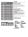
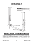
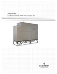
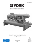
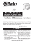
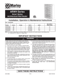
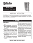
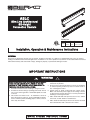
ASLC
Slim Line Architectural
Sill-Height
Convection Heaters
Dimensions
Type
ASLC
Height Width
6”
2-3/4”
152mm
70mm
Length
24” to 12’
610mm to 3658mm
Installation, Operation & Maintenance Instructions
GENERAL
This heater is designed to provide years of efficient, trouble free operation as a primary or supplemental heat source for comfort
heating in residential and commercial applications. Installation or use of this product in any manner not described within this manual
will void the warranty and could result in injury, damage to property, or permanent damage to heater.
IMPORTANT INSTRUCTIONS
WARNING
WHEN USING ELECTRICAL APPLIANCES, BASIC PRECAUTIONS SHOULD ALWAYS BE FOLLOWED TO REDUCE
THE RISK OF FIRE, ELECTRIC SHOCK, AND INJURY TO
PERSONS, INCLUDING THE FOLLOWING:
1. Read all instructions before installing or using the heater.
2. A heater has hot and arcing or sparking parts inside. Do not
use in areas where gasoline or flammable liquids are used
or stored.
3. This heater is hot when in use. To avoid burns, do not let
bare skin touch hot surfaces. Keep combustible materials,
such as furniture, pillows, bedding, papers, clothes, and curtains away from heater.
!
4. To prevent a possible fire, do not block air intakes or
exhaust in any manner.
5. Do not insert or allow foreign objects to enter any ventilation
or exhaust opening as this may cause an electric shock or
fire, or damage the heater.
6. Serious injury or death could result from electric shock.
Make sure electrical power supply circuit coming to heater
is disconnected at main disconnect or service panel before
installing or servicing this heater.
7. ASLC model with 250 watts per linear foot or less, without
wire mesh, are ETL listed for residential use.
8. ASLC model at 250 watts per linear foot must be mounted
above finished floor with a clearance of 2 inches.
SAVE THESE INSTRUCTIONS
Clearance Chart:
Table A - ASLC (Technical Data)
Catalog
Number
1125
1150
1188
1250
2100
2125
2150
2188
2250
3100
3125
3150
3188
3250
4100
4125
4150
4188
4250
5100
5125
5150
5188
5250
6100
6125
6150
6188
6250
7100
7125
7150
7188
7250
8100
8125
8150
8188
8250
9100
9125
9150
9188
9250
10100
10125
10150
10188
10250
Length
"L"
24”
(610mm)
28"
(711mm)
3'
(914mm)
4'
(1219mm)
5'
(1524mm)
6'
(1829mm)
7'
(2134mm)
8'
(2438mm)
9'
(2743mm)
10'
(3048mm)
Watts
per ft.
125
150
188
250
100
125
150
188
250
100
125
150
188
250
100
125
150
188
250
100
125
150
188
250
100
125
150
188
250
100
125
150
188
250
100
125
150
188
250
100
125
150
188
250
100
125
150
188
250
Total
Watts
250
300
376
500
200
250
300
376
500
300
375
450
564
750
400
500
600
752
1000
500
625
750
940
1250
600
750
900
1128
1500
700
875
1050
1316
1750
800
1000
1200
1504
2000
900
1125
1350
1692
2250
1000
1250
1500
1880
2500
120V
--3.1
-1.7
2.1
2.5
3.1
4.2
2.5
3.1
3.8
4.7
6.3
3.3
4.2
5
6.3
8.3
4.2
5.2
6.3
7.8
10.4
5
6.3
7.5
9.4
12.5
5.8*
7.3*
8.7
10.9*
14.5*
6.7*
8.3*
10
12.5*
16.7*
7.5*
9.4*
11.2*
14.1*
18.8*
8.3*
10.4*
12.5*
15.7*
--
208V
-1.4
1.8
2.4
1
1.2
1.4
1.8
2.4
1.4
1.8
2.2
2.7
3.6
1.9
2.4
2.9
3.6
4.8
2.4
3
3.6
4.5
6
2.9
3.6
4.3
5.4
7.2
3.4
4.2
5
6.3
8.4
3.8
4.8
5.8
7.2
9.6
4.3
5.4
6.5
8.1
10.8
4.8
6
7.2
9
12
Amperage
240V
277V
--1.3
-1.6
1.4
2.1
1.8
0.8
-1
0.9
1.3
1.1
1.6
1.4
2.1
1.8
1.3
1.1
1.6
1.4
1.9
1.6
2.4
2
3.1
2.7
1.7
1.4
2.1
1.8
2.5
2.2
3.1
2.7
4.2
3.6
2.1
1.8
2.6
2.3
3.1
2.7
3.9
3.4
5.2
4.5
2.5
2.2
3.1
2.7
3.8
3.2
4.7
4.1
6.3
5.4
2.9
2.5
3.6
3.2
4.4
3.8
5.5
4.8
7.3
6.3
3.3
2.9
4.2
3.6
5
4.3
6.3
5.4
8.3
7.2
3.8
3.2
4.7
4.1
5.6
4.9
7.1
6.1
9.4
8.1
4.2
3.6
5.2
4.5
6.3
5.4
7.8
6.8
10.4
9
347V
--------1.4
-1.1
1.3
1.6
2.2
1.2
1.4
1.7
2.2
2.9
1.4
1.8
2.2
2.7
3.6
1.7
2.2
2.6
3.3
4.3
2
2.5
3
3.8
5
2.3
2.9
3.5
4.3
5.8
2.6
3.2
3.9
4.9
6.5
2.9
3.6
4.3
5.4
7.2
For safe and efficient operation, maintain at least the following
minimum clearances at all times(see Fig. 1):
600V
-----------------1.3
1.7
-1
1.3
1.6
2.1
1
1.3
1.5
1.9
2.5
1.2
1.5
1.8
2.2
2.9
1.3
1.7
2
2.5
3.3
1.5
1.9
2.3
2.8
3.8
1.7
2.1
2.5
3.1
4.2
Bottom of Heater to Finished Floor:
• Front Inlet Models: (max 250 watts per foot)
- May be installed on floor if under 250 watts per foot.
However, for best performance, install bottom of heater
approximately 3 inches (76 mm) off floor. For models 250
watts per foot or more, bottom of units must be mounted at
least 2” off floor.
• Bottom Inlet Models:
- 100-250 watts per foot – 2 inch (51 mm)
Top of Heater to Ceiling (all models):
- Minimum 36 inches (914 mm)
Top of Heater to Bottom of Drapes (See Example 2):
- Minimum 6 inches (152 mm)
IMPORTANT NOTE: Certain fabrics and vinyl materials (such
as vinyl blinds) may become damaged by the heated air from
the heater and should not be installed above the heater.
Front of Heater to Full Length Drapes (See Example 1):
- Minimum between bottom of drapes and floor – 2-1/2 inches
(64 mm)
- Minimum between top of drapes and ceiling – 1/2 inch (13
mm)
- Minimum between front of heater and nearest fold of drape –
2 inches (51 mm)
Top of Heater to Bottom of Window Sill:
- Minimum 12 inches (305 mm)
*Available with 2 elements
CEILING
Example 1
Example 2
DRAPES
DRAPES
WALL
5
4
2
Maximum Allowable Current
4 to 5
Up to 2
3 to 4
conductors
conductors
conductors
4.5 Amps
5 Amps
7 Amps
6 Amps
7 Amps
9 Amps
10 Amps
12.0 Amps
WALL
No. 12 AWG
No. 10 AWG
No. 8 AWG
MIN. 1/2”
(13 mm)
MIN. 1/2”
(13 mm)
Table B. Sizing Field Installed Wiring
Max. No.
Copper wire wire installed
in wireway
size 90º C
CEILING
MIN. 6”
(152 mm)
MIN. 2”
(51 mm)
HEATER
HEATER
FLOOR
MIN. 2-1/2”
(64 mm)
Fig. 1: Clearance for Drapery
2
FLOOR
Rough in Wire
INSTALLATION INSTRUCTIONS
1. Run branch circuit of proper voltage and wire size to location
of left or right junction box as indicated on heater wiring diagram. Basic heaters are prewired and can be connected to
branch circuit at either end. Heaters with controls are
prewired for connection to branch circuit at one end only
(refer to heater wiring diagram). However, heater can be
wired from opposite end by running wires through heater
wireway. See Fig. 3 for knockout locations.
TO REDUCE THE RISK OF FIRE AND ELECTRIC SHOCK
OR INJURY TO PERSONS, OBSERVE THE FOLLOWING:
1. Serious injury or death could result from electric shock.
Make sure electrical power supply circuit coming to heater
are disconnected at main disconnect or service panel
before installing this heater.
2. Wiring procedures and connections must be in accordance
with the National Electrical Code (NEC) and local codes.
Refer to Wiring Diagram on heater and Figure 8. Make sure
all electrical connections are tight to prevent possible overheating. Use Copper Supply Wire Only.
3. Verify the electrical power supply voltage matches the voltage rating as printed on the heater nameplate.
CAUTION - Never connect a heater to a voltage greater than
the nameplate voltage as this will damage the heater and
could cause a fire.
2. If it is necessary to run wires through the heater wireway,
use Table B to size the field installed wiring.
3. The factory installed wires in the heater wireway can be
loaded up to 45 amps. Refer to Table C for maximum length
of heater run when the heaters are connected in parallel.
4. Do not install the heater against combustible low-density
cellulose fiberboard surfaces, against or below vinyl wall
coverings, or below any materials that may be damaged by
heat such as vinyl or plastic blinds, curtains, etc.
5. Do not install heater below an electrical convenience receptacle (outlet).
6. CAUTION – Heater operates at high temperatures. Keep
electrical cords (including telephone and computer cables),
drapes, and other furnishings away from heater. For efficient and safe operation, we recommend maintaining a minimum of 6 inches (152 mm) clearance above and in front of
the heater at all times. See Clearances Chart for minimum
clearance requirements.
7. To reduce the risk of fire, do not store or use gasoline or
other flammable vapors or liquids in the vicinity of the
heater.
8. Do not install heater upside down or in any position other
than as shown in this manual.
9. Do not recess heater in wall or install heater inside any type
enclosure as this will cause heater to overheat and could
create a hazard.
10. When mounting heater, use care when drilling mounting
holes and mounting heater to building structure to avoid
damaging internal heater components. Be sure to loosen
mounting screws ½ turn to allow for expansion and contraction.
11. Do not remove or bypass the safety limit control(s) (thermal
protectors) as this could allow heater to become a fire hazard, see heater wiring diagram supplied with heater.
12. The factory installed wires inside wireway are used to connect the built-in controls. Limit the maximum current to no
more than 45 total amp. Refer to instructions and current
capacity rating as provided with the accessory.
13. Heaters that are not installed end to end must have end
caps installed to cover exposed ends of heater.
14. When Transformer Relay Accessory is used in this heater,
all wiring within compartment where this device is installed
must be rated at least 90 °C.
15. Do not allow objects to be placed on top of heater as they
may be damaged or create a fire hazard.
16. To avoid damaging heater, do not use a screw driver to
separate front cover from back housing. Use only a putty
knife as shown, see Fig. 2
17. Before energizing, make sure front cover is properly locked
onto the back housing along the entire length of the heater,
see Fig. 5. Do not operate heater without front cover
installed.
Disconnect Switch:
20 amps @ 120-277 VAC
Thermostat:
25 amps @ 120-240 VAC
22 amps @ 277 VAC
Transformer Relay:
25
22
17
12
Power Relay
25 amps @ 120-277 VAC
Pneumatic/Electric
Switch
25 amps @ 120-277 VAC
amps
amps
amps
amps
@
@
@
@
120-240 VAC
277 VAC
347 VAC
600 VAC
NOTE: For mix of watt densities, calculate amp draw. Do not
exceed 45 amps.
4. Standard 90º C wiring must be used in junction boxes, wireways, blank sections, filler sections and corner sections.
Room Layout
Refer to heating plans for exact room arrangement of heaters
(with or without thermostats and/or relays and/or switches and
accessories).
Check the heater section dimensions and the additional wall
length required for filler sections or blank sections before starting wall-to-wall type installation. Be certain all heaters and
accessories needed are at hand and are of correct finish.
Mounting Height (see Clearance Chart)
NOTE: Up to 3/4” thick floor covering, such as carpets, tiles,
linoleum, etc., may be installed around and under the heater
without adversely affecting the performance of the heaters.
At correct height, draw a pencil line on the wall, level and/or
parallel with the window sill. Minimum mount heights above the
floor shall be as follows.
Installation of Single Unit
NOTE: For ease of installation, it is important that the sequence
of operation indicated below be followed in order. For heaters
with more than one heat deck, heat decks may be wired in parallel or each heat deck may be supplied by separate circuit. See
heater nameplate for current load for each heat deck.
1. Remove unit from carton and discard external pads and
plastic wrap.
2. Remove front cover by laying the heater on its back and
inserting a putty knife (or other thin, wide blade tool, 1”
[25mm] wide minimum) approximately 6” (152mm) from the
end of the heater and prying up as shown in Fig.2. This will
spring the snap lock closure open. Repeat as required down
the length of the heater until the front cover completely disengages from the heater back.
3
Putty knife or
other wide blade
tool
Cabinet front
cover
Recommended
mounting holes
drill area (for
wall mounting
Cabinet
back
housing
NOTE: Illustration shown only
to take off front cover.
Fig. 2
3. Remove appropriate electrical knockouts from either junction
box. See Fig. 3 for location of knockouts. If heater is to be
pedestal mounted, consult pedestal kit installation instructions.
Fig. 5
9. Following the wiring diagram secured to the heater, make
electrical connections. Ground the heater using the ground
screw provided. See Fig. 4.
10.Replace front cover by latching the bottom front edge of the
front cover over the bottom front edge of the back and pushing the cover straight back to latch the top rear edge of the
back with the top rear edge of the front cover. See Fig. 5.
4. Drill the required size mounting holes in the heater housing
(See Fig. 2 for recommended mounting hole location.)
5. Hold heater housing against the wall to check for evenness
of wall. Do not draw heater against an uneven wall surface. If
an uneven wall is encountered, use shims to keep the heater
housing straight.
1-3/8”
7/8”
(35mm) (22mm)
KO
KO
7/8” hole
1-3/8”
(35mm)
KO
Installation of Multiple Wall to Wall Units
NOTE: For ease of installation, it is important that the sequence
of operations indicated below be followed in order.
7/8”
(22mm)
KO
1. Repeat Steps 1 & 2 from Single Unit Installation.
2. Refer to wiring diagram for power supply entry and remove
appropriate electrical knockout (Fig. 3) from the heater in
which power supply connections are to be made. The power
supply may be brought into the end of one heater and the
remaining heaters may be connected in parallel using the
wireway. Use Table B to size the field installed wiring in the
wireway or use Table A to determine the maximum length or
heater run possible using the factory installed wire in the
heater wireway.
Back
Junction
Box
E
E
H
W
ASLC
A 1.27” (32)
B 2.00”(51)
C 1.63” (41)
D 1.37”(35)
E 2.75”(70)
H 2.71”(69)
W 1.25”(32)
X 1.00(25.4)
in. (mm)
X
D
1-23/32”
(44mm)
KO
A
Bottom
D
C
3. If filler sections, inside corners, outside corners, splice kits or
end caps are to be used, consult convector accessory installation instructions. If units are to be pedestal mounted, consult the convector accessories installation instructions.
Pedestal placement and
KOs shown are for standard
units. Custom enclosures
and/or heat decks will have
pedestal placement and
KOs in various locations.
Consult factory.
NOTE: If a heater has a disconnect switch and/or thermostat
and is to have a filler section at either end, the filler must not
cover the access to those controls.
Fig. 3
4. If the run of the heaters includes an inside corner or an outside corner, mount corner to wall (see accessory installation
instructions packed with corners), then mount heater.
6. Run proper size branch circuit to the junction box through the
selected knockout.
5. Drill the required size mounting holes in all the heater housings. (See Fig. 2 for recommended mounting hole location.)
7. Mount the heater on the wall using screws, bolts or anchors
(by installer) to suit the wall construction.
6. Hold heater housings against wall to check for evenness of
the wall. Do not draw the heaters against an uneven wall
surface. If an uneven wall is encountered, use shims to keep
the heater housing straight.
B
8. Tighten mounting screw and back off 1/2 turn to allow for
expansion and contraction of the heater.
7. Run proper size branch circuit to the junction box through the
selected knockout.
Junction Box
8. Mount the heaters on the wall using screws, bolts or anchors
(by installer) which suit the wall construction. Alignment tabs
can be inserted in adjoining back housings to assure even
alignment. See Fig. 6 for details.
9. Following the wiring diagram secured to the heater, make the
electrical connections. Refer to Fig. 8 to connect the other
heaters in parallel. Grounding of the other heaters is accomplished by connecting a jumper wire (not supplied) between
the two adjacent heaters.
Ground Screw
10.Replace front covers following Step 10 under Single Unit
Installation, (See Fig. 5.)
Fig. 4
4
MAINTENANCE INSTRUCTIONS
Alignment
Tab
Your heater will give your years of service and comfort with only
minimal care. The user can perform periodic cleaning of the
exterior cabinet, but all other interior cleaning and servicing
should be done by a qualified service person.
Back
Housing
Note: For efficient and safe operation, airflow must not be
restricted in and around the heater. As air moves through the
heater by convection, dust and lint may accumulate in the
heater and around the heating element that needs to be cleaned
periodically. It is recommended that your heater be cleaned and
inspected for damage at least annually (or more often if
needed).
Fig. 6
Blank Sections
Blank sections, if any, are installed in the same manner as the
heaters.
1. Serious injury or death could result from electric shock.
Make sure electrical power supply circuit(s) coming to
heater is/are disconnected at main disconnect or service
panel before servicing this heater. Allow heater to cool
before cleaning to prevent a possible burn.
OPERATION INSTRUCTIONS
1. After heater(s) are completely assembled and installed, set
thermostat or operating controls for NO HEAT and energize
the heater circuit (s). Verify the heater(s) are not producing
heat.
Note: More than one power source may enter heater.
Be sure all power is disconnected to heater before
cleaning or servicing.
2. Adjust thermostat or operating control to call for heat. Allow
heater(s) to operate for a few minutes and verify all heaters
are producing heat.
2. Use care when cleaning element fins to avoiding damaging
fins. Note also that fins are sharp and may cause cuts so
avoid contact.
Note: during initial start up, heaters may exhibit a new smell
and possibly some slight smoke from the manufacturing
residues on the heating element. Allow heaters to operate for
approximately 30 minutes to dissipate these residues.
Ventilating the area may be desired.
1. The exterior of the heater may be cleaned with a damp cloth.
However, do not use harsh cleaners, polishes, or waxes as
these may damage the surface or leave a residue that will
discolor.
3. To set thermostat or operating controls to maintain desired
comfort level, allow heaters to operate until room ambient
temperature reaches the desired level. The thermostat or
operating control can then be adjusted to maintain this temperature.
2. To clean interior of heater will require the removal of the front
cover. To remove the front cover, disengage the top rear
snap-lock first. Use an “L” shaped tool, such as an Allen
Wrench, to lift up under the webs between the back row of
slots (See Fig. 7). Start at either end and lift up on the front
cover until the tension in the cover pulls the cabinet apart.
Continue moving along the length of the heater until the
cover comes off.
Note: when built-in thermostat and/or disconnect switch is/or
provided, access to these controls will be through grille openings
at either end of the heater. To rotate the thermostat shaft will
require a small flat blade screw driver. The disconnect switch is
a rocker switch that can be operated with the same screw driver
or tool through the openings.
3. With front cover removed, a vacuum cleaner or compressed
air can be used to clear dust and lint from inside heater and
around the heating element. Fins are sharp and may cause
cuts so avoid contact by hands. Use care to not damage the
aluminum fins.
4. If built-in thermostat is provided, after room reaches desired
comfort level, rotate thermostat shaft counterclockwise until
the thermostat clicks. This should allow the thermostat to
cycle the heater on and off to maintain this temperature.
Rotation in the clockwise direction will allow the heater to
remain ON MORE and will maintain a HIGHER room ambient. Likewise, rotation in the counterclockwise direction will
result in the heater remaining ON LESS and the room ambient will be LOWER. If remote thermostat or other types of
controls are provided, refer to the instructions provided with
these controls for proper operation.
Allen Wrench or
other 90º tool
IMPORTANT NOTE: These heaters are provided with a built-in
safety limit (Thermal Protector– see Fig. 8) to automatically turn
off the heater if it is blocked or otherwise overheats due to an
abnormal condition. The heaters should not be cycling off on
this safety control during normal use. If this is occurring, check
heater installation to assure it has adequate clearances and the
free airflow around heater is not restricted. If heater continues
to cycle on this safety control, discontinue using until it can be
inspected and/or repaired by a qualified electrician.
Front Cover
Fig. 7
4. As a matter of normal maintenance, check remainder of
heater for damage or possible maintenance issues while
cover is removed and make any repairs needed.
5. Replace front cover as shown in Fig. 5 making sure it is
locked in position along length of heater. Restore power to
heater and verify it is operating properly.
5
Typical Wiring of Multiple Heaters (without controls)
Thermal Protector
Thermal Protector
Element
Element
Ground Screw
To other
heater
Ground Screws
To other
heater
No. 10 Wires
No. 10 Wires
Factory Wiring
Field Wiring
Power Supply to Circuit Breaker
Fig. 8
LIMITED WARRANTY
All products manufactured by Marley Engineered Products are warranted against defects in workmanship and materials for one year from date of installation, except
heating elements which are warranted against defects in workmanship and materials for five years from date of installation. This warranty does not apply to damage from
accident, misuse, or alteration; nor where the connected voltage is more than 5% above the nameplate voltage; nor to equipment improperly installed or wired or
maintained in violation of the product’s installation instructions. All claims for warranty work must be accompanied by proof of the date of installation.
The customer shall be responsible for all costs incurred in the removal or reinstallation of products, including labor costs, and shipping costs incurred to return products
to Marley Engineered Products Service Center. Within the limitations of this warranty, inoperative units should be returned to the nearest Marley authorized service center or the Marley Engineered Products Service Center, and we will repair or replace, at our option, at no charge to you with return freight paid by Marley. It is agreed that
such repair or replacement is the exclusive remedy available from Marley Engineered Products.
THE ABOVE WARRANTIES ARE IN LIEU OF ALL OTHER WARRANTIES EXPRESSED OR IMPLIED, AND ALL IMPLIED WARRANTIES OF MERCHANTABILITY AND
FITNESS FOR A PARTICULAR PURPOSE WHICH EXCEED THE AFORESAID EXPRESSED WARRANTIES ARE HEREBY DISCLAIMED AND EXCLUDED FROM
THIS AGREEMENT. MARLEY ENGINEERED PRODUCTS SHALL NOT BE LIABLE FOR CONSEQUENTIAL DAMAGES ARISING WITH RESPECT TO THE
PRODUCT, WHETHER BASED UPON NEGLIGENCE, TORT, STRICT LIABILITY, OR CONTRACT.
Some states do not allow the exclusion or limitation of incidental or consequential damages, so the above exclusion or limitation may not apply to you. This warranty gives
you specific legal rights, and you may also have other rights which vary from state to state.
For the address of your nearest authorized service center, contact Marley Engineered Products in Bennettsville, SC, at 1-800-642-4328. Merchandise returned to the factory must be accompanied by a return authorization and service identification tag, both available from Marley Engineered Products. When requesting return authorization,
include all catalog numbers shown on the products.
HOW TO OBTAIN WARRANTY SERVICE AND
WARRANTY PARTS PLUS GENERAL INFORMATION
1. Warranty Service or Parts
2. Purchase Replacement Parts
3. General Product Information
1-800-642-4328
1-800-654-3545
www.marleymep.com
470 Beauty Spot Rd. East
Bennettsville, SC 29512 USA
When obtaining service always have the following:
1. Model number of the product
2. Date of manufacture
3. Part number or description
Part No. 5200-11062-000
PPD 15761
06/11