1
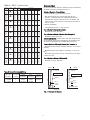
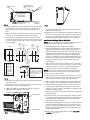
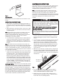
Rough in Wire
INSTALLATION INSTRUCTIONS
1. Run branch circuit of proper voltage and wire size to location
of left or right junction box as indicated on heater wiring diagram. Basic heaters are prewired and can be connected to
branch circuit at either end. Heaters with controls are
prewired for connection to branch circuit at one end only
(refer to heater wiring diagram). However, heater can be
wired from opposite end by running wires through heater
wireway. See Fig. 3 for knockout locations.
TO REDUCE THE RISK OF FIRE AND ELECTRIC SHOCK
OR INJURY TO PERSONS, OBSERVE THE FOLLOWING:
1. Serious injury or death could result from electric shock.
Make sure electrical power supply circuit coming to heater
are disconnected at main disconnect or service panel
before installing this heater.
2. Wiring procedures and connections must be in accordance
with the National Electrical Code (NEC) and local codes.
Refer to Wiring Diagram on heater and Figure 8. Make sure
all electrical connections are tight to prevent possible overheating. Use Copper Supply Wire Only.
3. Verify the electrical power supply voltage matches the voltage rating as printed on the heater nameplate.
CAUTION - Never connect a heater to a voltage greater than
the nameplate voltage as this will damage the heater and
could cause a fire.
2. If it is necessary to run wires through the heater wireway,
use Table B to size the field installed wiring.
3. The factory installed wires in the heater wireway can be
loaded up to 45 amps. Refer to Table C for maximum length
of heater run when the heaters are connected in parallel.
4. Do not install the heater against combustible low-density
cellulose fiberboard surfaces, against or below vinyl wall
coverings, or below any materials that may be damaged by
heat such as vinyl or plastic blinds, curtains, etc.
5. Do not install heater below an electrical convenience receptacle (outlet).
6. CAUTION – Heater operates at high temperatures. Keep
electrical cords (including telephone and computer cables),
drapes, and other furnishings away from heater. For efficient and safe operation, we recommend maintaining a minimum of 6 inches (152 mm) clearance above and in front of
the heater at all times. See Clearances Chart for minimum
clearance requirements.
7. To reduce the risk of fire, do not store or use gasoline or
other flammable vapors or liquids in the vicinity of the
heater.
8. Do not install heater upside down or in any position other
than as shown in this manual.
9. Do not recess heater in wall or install heater inside any type
enclosure as this will cause heater to overheat and could
create a hazard.
10. When mounting heater, use care when drilling mounting
holes and mounting heater to building structure to avoid
damaging internal heater components. Be sure to loosen
mounting screws ½ turn to allow for expansion and contraction.
11. Do not remove or bypass the safety limit control(s) (thermal
protectors) as this could allow heater to become a fire hazard, see heater wiring diagram supplied with heater.
12. The factory installed wires inside wireway are used to connect the built-in controls. Limit the maximum current to no
more than 45 total amp. Refer to instructions and current
capacity rating as provided with the accessory.
13. Heaters that are not installed end to end must have end
caps installed to cover exposed ends of heater.
14. When Transformer Relay Accessory is used in this heater,
all wiring within compartment where this device is installed
must be rated at least 90 °C.
15. Do not allow objects to be placed on top of heater as they
may be damaged or create a fire hazard.
16. To avoid damaging heater, do not use a screw driver to
separate front cover from back housing. Use only a putty
knife as shown, see Fig. 2
17. Before energizing, make sure front cover is properly locked
onto the back housing along the entire length of the heater,
see Fig. 5. Do not operate heater without front cover
installed.
Disconnect Switch:
20 amps @ 120-277 VAC
Thermostat:
25 amps @ 120-240 VAC
22 amps @ 277 VAC
Transformer Relay:
25
22
17
12
Power Relay
25 amps @ 120-277 VAC
Pneumatic/Electric
Switch
25 amps @ 120-277 VAC
amps
amps
amps
amps
@
@
@
@
120-240 VAC
277 VAC
347 VAC
600 VAC
NOTE: For mix of watt densities, calculate amp draw. Do not
exceed 45 amps.
4. Standard 90º C wiring must be used in junction boxes, wireways, blank sections, filler sections and corner sections.
Room Layout
Refer to heating plans for exact room arrangement of heaters
(with or without thermostats and/or relays and/or switches and
accessories).
Check the heater section dimensions and the additional wall
length required for filler sections or blank sections before starting wall-to-wall type installation. Be certain all heaters and
accessories needed are at hand and are of correct finish.
Mounting Height (see Clearance Chart)
NOTE: Up to 3/4” thick floor covering, such as carpets, tiles,
linoleum, etc., may be installed around and under the heater
without adversely affecting the performance of the heaters.
At correct height, draw a pencil line on the wall, level and/or
parallel with the window sill. Minimum mount heights above the
floor shall be as follows.
Installation of Single Unit
NOTE: For ease of installation, it is important that the sequence
of operation indicated below be followed in order. For heaters
with more than one heat deck, heat decks may be wired in parallel or each heat deck may be supplied by separate circuit. See
heater nameplate for current load for each heat deck.
1. Remove unit from carton and discard external pads and
plastic wrap.
2. Remove front cover by laying the heater on its back and
inserting a putty knife (or other thin, wide blade tool, 1”
[25mm] wide minimum) approximately 6” (152mm) from the
end of the heater and prying up as shown in Fig.2. This will
spring the snap lock closure open. Repeat as required down
the length of the heater until the front cover completely disengages from the heater back.
3